manuals.online logo
Brands
  1. Home
  2. •
  3. Brands
  4. •
  5. ABB
  6. •
  7. Lighting Equipment
  8. •
  9. ABB Stanilite Nexus RF User manual

ABB Stanilite Nexus RF User manual

—
INSTALLATION MANUAL
Stanilite®
Platinum exit LED edgelit recessed
Nexus® RF
Doc no. 29-WLIS001_B
This document covers What’s inside the box
Safety warning Recessed base assembly
Installation instructions Diffuser assembly
Removal instructions Ceiling cut-out template
Testing precautions Picto diffuser insert pack
Troubleshooting guide Mains power cord
Data plug (for Nexus only)
Cable ties
Installation manual
Warranty information
Troubleshooting guide
If you have installed and connected the fitting as per the instructions listed earlier and it does
not function correctly, use the following table as a guide to fixing the problem. Look up the
type of fault in the left column and check the possible causes from the right column.
If the fitting still does not work after checking these possible causes, contact ABB customer
service in Australia on 1800 60 20 20.
—
ABB Australia Pty Limited
For enquiries
ABB contact centre: 1800 60 20 20
E-mail: AU-ABB-Stanilite@abb.com
www.stanilite.com.au © Copyright 2019 ABB. All rights reserved.
9AKK1074920279 - B - Jul 2019
Construction sites
Continuously switching off the mains power
supply that is connected to emergency light
fittings during the construction phase of an
installation will cause these fittings to discharge
and charge their batteries many times over a
short period; this can shorten life of the battery.
ABB does not recommend such practices and
may not honour the warranty on batteries when
they are subjected to such harsh operating
conditions. Emergency light fittings are designed
to be discharge tested once every 6 months as
per AS/NZS 2293.2, subjecting the product to
repeated discharge or charge cycles is regarded
as an abuse of the fittings.
No. Fault Possible causes
1LED lamp and indicator LED not lit AC supply not connected; or
AC supply turned off; or
Test switch damaged
2LED lamp not lit but red indicator is lit LED lamp damaged; or
LED lamp plug incorrectly inserted in the mother board
3LED lamp not lit but indicator LED is flashing green LED lamp damaged; or
LED lamp plug incorrectly inserted in the mother board
4LED lamp is lit but red indicator LED not lit LED damaged; or
Check battery connection
5The LED lamp does not switch to emergency mode
when the test button is pressed
Test switch damaged
6Indicator LED is constant green Test switch damaged; or
Self check fail - return to factory
7Indicator LED not red after commissioning Check battery connection and battery plug polarity
8The LED lamp works momentarily on emergency
when the test button is pressed or tested by
command from the Nexus system
Battery not yet charged (allow up to 24 hours)
Testing precautions
Once the fitting is permanently connected to the
mains supply, a commissioning discharge test as
required in AS/NZS 2293.2 must be carried out.
You will need to allow 24 hours for the battery to
fully charge prior to conducting this test,
presently (at the time of writing), the standard
requires that fittings operate in emergency mode
for a period not less than 2 hours for their
commissioning test and for not less than 90
minutes thereafter (it is required that 6 monthly
discharge tests be carried out). You will need to
keep the records for the commissioning test and
enter them into the building emergency services
logbook or via other recording methods as
allowed by AS/NZS 2293.2.
Thank you for choosing ABB product
Please read this document thoroughly before
commencing installation and retain for future
reference. Contact ABB customer service in
Australia on 1800 60 20 20 if you need any
assistance. The installation instructions were
correct at the time of print. To reflect changes in
technology and Australian standards; ABB
reserves the right to amend the instructions
without notice. Updated document can be found
on the Stanilite website.
Safety warning
In Australia and New Zealand, only licensed
electricians are permitted by law to work with
240 volt electrical installations.
Do not attempt to install or connect this product
unless you are a licensed electrician.
Turn off and isolate the electrical supply before
connecting this fitting to the building wires.
Do not touch the terminals of the terminal block
when the light fitting is energised.
The only user-serviceable part is the battery
pack. LED light source is not user-serviceable.
Do not attempt to service other parts of the
fitting as this will void the warranty.
As the installer, it is your responsibility to ensure
compliance with all relevant building and safety
codes, (ie: AS/NZS 3000, AS/NZS 2293). Refer to
the applicable standards for data and mains
cabling installation procedures and
requirements.
As per AS 60598.2.2:2016 the recessed luminaire
classification is CA90.
Note: Not suitable for use with loose-fill
insulation.
No fire rated box is required for the product.
Important to note:
• This product is designed for indoor use only.
Nexus RF (wireless system)
The Nexus RF range of light fittings are designed to
communicate via a proprietary RF network, however
the electrical installation of the fittings is identical
to that of a standard non-monitored fitting.
Installation instructions
Note: Due to additional insulation sheet inside the fitting, the diffuser needs to be installed before
recessing the fitting into the ceiling.
Note: The circuit supplying mains power to the fitting must not be energised until installation of
the fitting is completed.
1. Take out the cut-out template (348mm x 97mm) from the packing box; use a pencil to mark the cut-
out position on the ceiling.
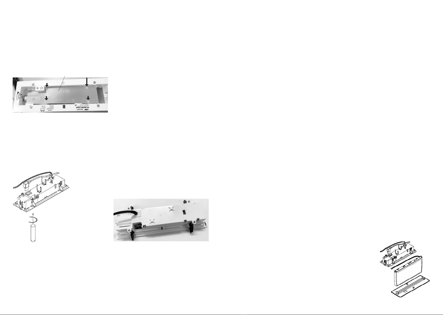
2. Preparation of fittings. Remove face plate, connect the diffuser wire loom to the main board and
lay the wire loom carefully inside the base. Connect the battery. Insert 4 nylon stand posts to the
mounting holes in the main board. Align the holes in the insulation sheet to the 4 stand posts.
Firmly press down and secure the insulation sheet to the stand posts. Refer figure 1.
3. Fixing the diffuser. Insert one side of the diffuser in the diffuser holding latch hole and push the
diffuser to the latching hole in the opposite side until the diffuser clicks and locks in place.
4. Installing the fittings to the ceiling cut-out. Recess the base assembly through the ceiling cut-out
(if access to the ceiling cavity is not available, connect the mains power cord and Nexus data cable,
secure with the cable ties supplied, before recessing the base in the ceiling cut-out). Once
recessed in the cut-out, tighten the cam lock screws using suitable size Philips screwdriver or a
power-driven screwdriver set at minimum torque, turning clockwise (refer figure 2), to secure the
product to the ceiling. Connect the mains power cord and Nexus data cable if not connected earlier
and secure with the cable ties supplied.
5. Hold the face plate in your hand; make sure the rectangular hole in the face plate for the LED and
test switch lines up with LED and test switch in the base. Bring up the face plate close to the base,
place the locking tab on one side in the position, the other end locking tab should line up on the
correct position. Once both the locking tabs are in the correct position, press gently, till it clicks
and locks. Press gently in the middle to lock middle 2 tabs, click sound indicates the tabs are
locked in position.
6. Install the pictograph inserts by sliding into the diffuser. The pictograph inserts can be installed in
the diffuser prior to installing the diffuser assembly in the fitting. Fitting is supplied standard
with all pictograph insert options for single and double sided, as complete one box solution to
meet any site/project needs.
Removal instructions
1. To remove/uninstall fitting from the ceiling,
the steps to be followed are the reversal of
installation process. Turn off mains power to
fitting, the fitting will automatically switch
into emergency mode as the mains power has
been turned off. It will stay on the emergency
mode until such time as the battery cut-off
threshold is reached.
2. Remove face plate, gently insert a small
screwdriver into the first slot (first slot is
close to the diffuser end) and pull down
gently, repeat the same on the other end to
remove face plate.
3. To remove diffuser assembly, hold the
diffuser holding latch with thumb on one end
and push gently to the opposite end to
remove diffuser from the holding latch. Once
diffuser is removed from the latch,
disconnect/remove wire loom plug from the
mother board. Once the diffuser assembly is
removed, disconnect the battery pack plug on
the mother board.
4. Loosen the cam lock screws using suitable
size Philips screwdriver or a power driven
screwdriver set at minimum torque, turning
anti-clockwise. Once the cam lock screws are
loosened, the recessed base assembly can be
pulled down gently from the ceilng cut-out,
pull out the mains power cord from the back
of base.
5. When the fitting is reconnected to the mains
supply, it will need time to recharge its
battery before it will be capable of a full
length discharge again. The ability of the
fitting to operate
on emergency is
determined by the
age, charge level,
operating
temperature
conditions and
environmental
circumstances of
the battery in the
fitting.
7. The circuit supplying mains power to the fitting can now be energised. Once powered up, in a
single point unit red LED lamp should energise and remain lit on mains, until the power supply fails.
For Nexus product; the normal initial uncommissioned status of the indicating LED on the fitting is
flashing green. Once commissioned, the LED changes to a steady red and flashes red during test
when receives command from the Nexus system. Please refer to the Nexus user and technical
guide for a full detailed description of all possible LED states and their meanings. The emergency
function of the fitting should only operate when the normal lighting power supply fails or when
somebody presses the manual test button located on the fitting or when commissioned on the
Nexus network and the fitting receives a command from the Nexus controller to switch into
emergency mode.
8. Check the operation of the fitting to ensure that the installation was successful. When powered
up, allow a few minutes to give the battery a small charge, then press the manual test button
9. Hold the test button in for a few seconds and observe the operation of the lamp switching from
mains to the emergency mode. If the lamp on emergency mode works momentarily, that’s okay.
Try again in a few more minutes because if the battery was completely discharged, it may take a
little time to charge up enough to operate even momentarily. After this time, press the test button
again and if the lamp does not work at all, check the supply, the connections and the
troubleshooting guide at the end of this document.
10. Once manually checked as per item 7 above, the Nexus fitting is ready to be communication tested
and commissioned into the Nexus network and registered in the database. Keep the information
details of this fitting including exact location description, DB (distribution board) and CB (circuit
breaker) numbering, channel and router numbering, plan number and cross referencing
information as all this will be required for entry into the database during commissioning. Refer to
the Nexus user and technical guide for full details.
Figure 3: Product installed in ceilingFigure 2: Tight cam lock screw using Philips screwdriver
Figure 4
Figure 1: Preparation of fittings
Insulation sheet Stand post x 4
Important: 24 hours is required to allow the fitting battery to reach full capacity, ie: prior to a
discharge test. As the installer, it is your responsibility to conduct the initial discharge testing of
the installed fitting. Refer to AS/NZS 2293.

Other ABB Lighting Equipment manuals

ABB Stanilite Standard User manual

ABB

ABB Stanilite Standard User manual

ABB Emergi-Lite Serenga Sun-Lite Manual

ABB

ABB Emergi-Lite Serenga Sun-Lite Manual

ABB PrimEvo TW220E Manual

ABB

ABB PrimEvo TW220E Manual

ABB Stanilite Spitfire Standard User manual

ABB

ABB Stanilite Spitfire Standard User manual

ABB Stanilite Quickfit Nexus LX User manual

ABB

ABB Stanilite Quickfit Nexus LX User manual

ABB EGNL Series User manual

ABB

ABB EGNL Series User manual

ABB Stanilite Emergency User manual

ABB

ABB Stanilite Emergency User manual

ABB KAUFEL Lutia Manual

ABB

ABB KAUFEL Lutia Manual

ABB GE ReliaGear Lighting Panelboard User manual

ABB

ABB GE ReliaGear Lighting Panelboard User manual

ABB EMERGI-LITE Guideway Manual

ABB

ABB EMERGI-LITE Guideway Manual

ABB Stanilite Quickfit Standard User manual

ABB

ABB Stanilite Quickfit Standard User manual

ABB EMERGI-LITE Guideway Manual

ABB

ABB EMERGI-LITE Guideway Manual

ABB Stanilite Spitfire Standard User manual

ABB

ABB Stanilite Spitfire Standard User manual

ABB Thomas&Betts Standard User manual

ABB

ABB Thomas&Betts Standard User manual

ABB Stanilite Standard User manual

ABB

ABB Stanilite Standard User manual

ABB EMERGI-LITE Serenga Manual

ABB

ABB EMERGI-LITE Serenga Manual

ABB Thomas & Betts Standard User manual

ABB

ABB Thomas & Betts Standard User manual

ABB Stanilite Economy e-Luna circular LED User manual

ABB

ABB Stanilite Economy e-Luna circular LED User manual

ABB PrimEvo SM100E Manual

ABB

ABB PrimEvo SM100E Manual

ABB Stanilite User manual

ABB

ABB Stanilite User manual

ABB Thomas & Betts Standard User manual

ABB

ABB Thomas & Betts Standard User manual

ABB Stanilite Spitfire Standard User manual

ABB

ABB Stanilite Spitfire Standard User manual

Popular Lighting Equipment manuals by other brands

HSS Hire 57481 Operating & safety guide

HSS Hire

HSS Hire 57481 Operating & safety guide

LIFX BEAM manual

LIFX

LIFX BEAM manual

Emos ZY1438 manual

Emos

Emos ZY1438 manual

Event Lighting DELUGE27X15 user manual

Event Lighting

Event Lighting DELUGE27X15 user manual

PR Lighting CUBIX300 user manual

PR Lighting

PR Lighting CUBIX300 user manual

CCS MFU Series instruction manual

CCS

CCS MFU Series instruction manual

Clas Ohlson TF12865 instruction manual

Clas Ohlson

Clas Ohlson TF12865 instruction manual

Cameo ZENIT W300i user manual

Cameo

Cameo ZENIT W300i user manual

Chauvet Hurricane 901 Quick reference guide

Chauvet

Chauvet Hurricane 901 Quick reference guide

UFO GEM SLP-3000M user guide

UFO

UFO GEM SLP-3000M user guide

Jolly LT-1220 user manual

Jolly

Jolly LT-1220 user manual

Light Sky SHARK450 user manual

Light Sky

Light Sky SHARK450 user manual

Elation COLOR SPOT 150 user manual

Elation

Elation COLOR SPOT 150 user manual

Lightolier Lytespan 7610 specification

Lightolier

Lightolier Lytespan 7610 specification

Infinity SM-205 Technical manual

Infinity

Infinity SM-205 Technical manual

EFFILUX EFFI-FLEX-LG user manual

EFFILUX

EFFILUX EFFI-FLEX-LG user manual

Chimera 4' Octa Instructions for care and use

Chimera

Chimera 4' Octa Instructions for care and use

Artecta Par 16 Tracklight Warm on Dim V1 user manual

Artecta

Artecta Par 16 Tracklight Warm on Dim V1 user manual

manuals.online logo
manuals.online logoBrands
  • About & Mission
  • Contact us
  • Privacy Policy
  • Terms and Conditions

Copyright 2025 Manuals.Online. All Rights Reserved.