Pfannenberg Quadro-LED HI User manual

085 501 980c 3 30084-004-9c
1. Description and use
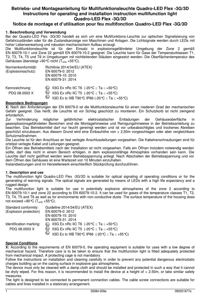
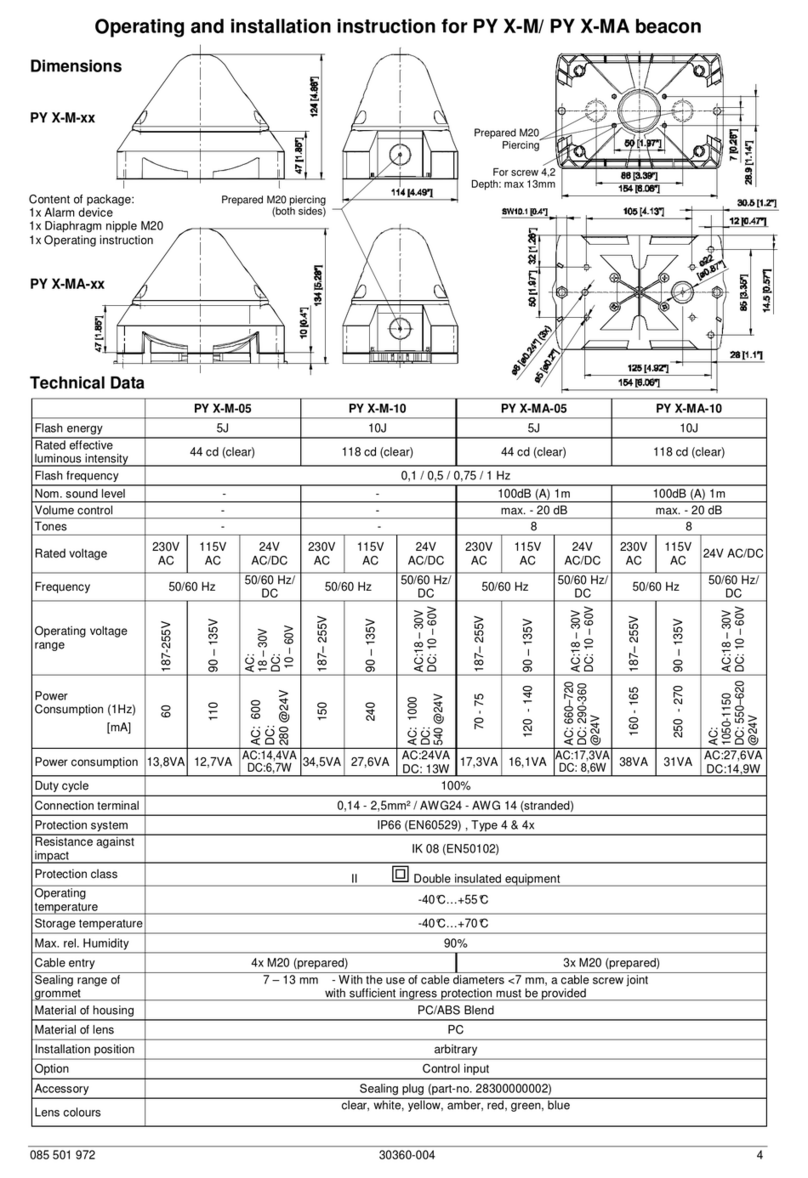
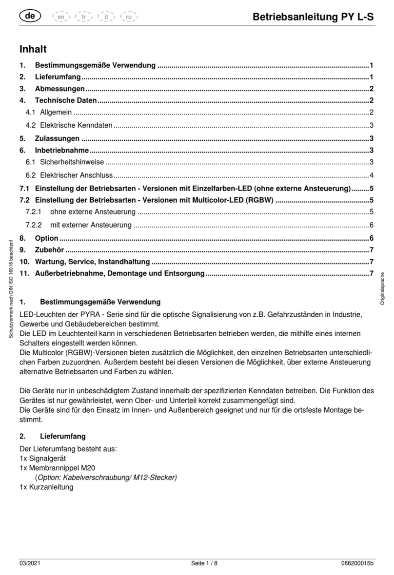
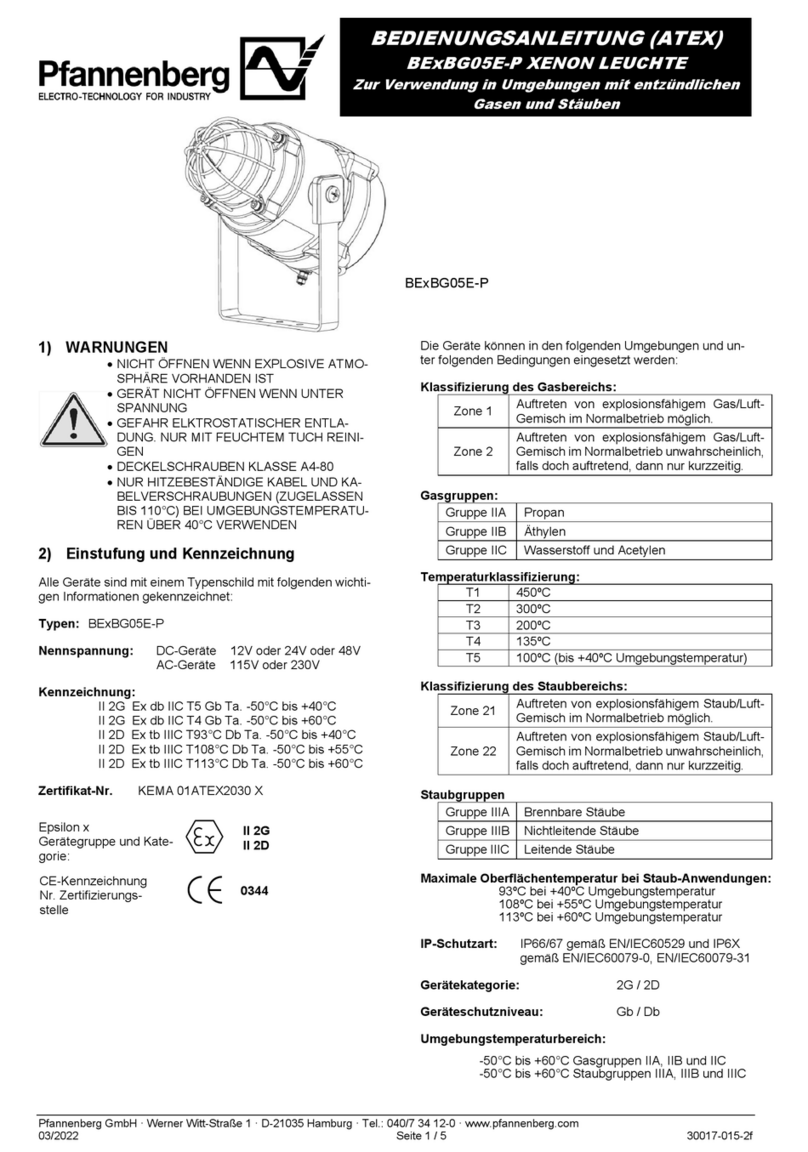
The multifunction light Quadro-LED HI is suitable for optical signaling of operating conditions or for the generating of warning
signals. The optical signals are generated by means of LEDs with a high light yield and a rugged design.
The device is designed for applications inside or outside buildings. Neither aggressive environmental conditions nor heavy rain
nor dew formation can cause damage. Internal dew formation is admissible.
2. Installation
By loosening of the four recessed head screws in the hood it can be lifted off upwards. The fastening drill holes of the housing
are then accessible. Mounting can be achieved by means of these fastening drill holes or with the enclosed brackets. The
mounting position is arbitrary.
The best method of installing the light is to mount it at their final location using bolts or similar fixing materials.
3. Technical Data
Operating and installation instruction for multifunction light Quadro-LED HI
DC version
Electrical Data
Nom. voltage 12 V DC / 24 V DC / 48 V DC +/- 10 %
Voltage range 11 V .. 60 V DC
Voltage range for
control inputs 11 V .. 60 V DC
Current
consumption RMS
[mA]
all colors except red LED red
12V
DC
24V
DC
48V
DC
12V
DC
24V
DC
48V
DC
Continuous light 390 220 110 360 195 100
Blinking light 1Hz 280 155 80 260 135 70
Blinking light 2Hz 280 155 80 260 135 70
Flashing light
0,1Hz 105 55 30 100 45 25
Flashing light
0,5Hz 230 120 60 215 100 55
Flashing light
0,75Hz 270 140 75 265 120 65
Flashing light 1Hz 320 165 85 305 165 60
Flashing light 2Hz 450 230 120 430 200 90
Duty cycle 100%
Service life > 50 000h
Mechanical Data
Ingress protection IP 66/67 (EN 60529) Mounting position arbitrary
Resistance against
impact IK08 (EN50102)
Protection class II
Cable entry sideways 2x M20/M32
base 2x M20
Terminals Cage clamp 0,08-2,5mm²
Weight 0,5 kg
Housing material PC (Polycarbonat) light grey
Material of lens PC (Polycarbonat)
Climatic Data
Operating
temperature - 40 °C .... + 55 °C
Storage
temperature - 40 °C .... + 70°C
rel. Humidity 90%
Optical Data
Light intensity * max. 75 cd (Blondel + Rey)
Illuminant 4x High-output LED
* The light intensity depends on lens color and operation mode.
130 [5.12"]
130 [5.12"]
47 [1.85"]
e.g. 4x M4x20
25 [0.98"]
80 [3.15"]
113.5 [4.47"]
113.5 [4.47"]
39 [1.54"]
Cutout prepared
Cutout prepared
M20/M32
Fixing bolt
M20
37 [1.46"]

085 501 980c 4 30084-004-9c
4. Taking into operation
Before commissioning the information provided on the rating plate and in these instructions is to be observed. Non- obser-
vance can lead to the destruction of the beacon and to the jeopardising of safety.
The light is designed to be connected to permanent connection cables. The cable screw connections are suitable for cables
and lines installed in a stationary arrangement.
After connecting it to the power supply and fixing/tightening the hood in place, the multifunction light is ready for operation. A
subsequent test is made to ensure satisfactory functional integrity.
Caution: In order to avoid damage to eyesight, please refrain from looking at the light for any length of time when it is in op-
eration.
Reverse voltage protection!
No function when polarity is reversed.
Control of light intensity
X2
External control input
Wire connection
X1
Connection terminal
1234
+
-
421 3
S1
Selection of operation mode
S1 Operation
mode
Switching through C1 to
operation mode no. ...
Switching through C2
to operation mode no..
Switching through C1
+ C2 to operation mode
no. ..
123
OFF OFF OFF 1 Standby for external
control 324
OFF OFF ON 2 Flashing light 1 Hz 6--6
OFF ON OFF 3 Continuous light -- 4 4
OFF ON ON 4 Blinking light 1 Hz -- -- --
ON OFF OFF 5 Flashing light 2 Hz 768
ON OFF ON 6 Blinking light 2 Hz 8--8
ON ON OFF 7 Flashing light 0,1 Hz -- 8 8
ON ON ON 8 Flashing light 0,5 Hz -- -- --
Position of S1.4 = ON when using external control
Example for selection via C1
C1 C1 C2 C2
1234
+
-
X1X2
4. Maintenance, Service and Ordering Spare Parts
The multifunction light is maintenance-free.
The polycarbonate housing may only be cleaned with water and a mild detergent solution.
As a principle, repairs are to be carried out at the manufacturer’s factory. Parts (only use original spare parts) can be replaced
by suitably qualified personnel.

085 501 980c 1 30084-004-9c
1. Beschreibung und Verwendung
Bei der Quadro-LED HI handelt es sich um eine Multifunktions-Leuchte zur optischen Signalisierung von Gefahrzuständen
oder für die Zustandsanzeige von Maschinen und Anlagen. Die Lichtsignale werden durch LEDs mit hoher Lichtausbeute und
robusten mechanischem Aufbau erzeugt.
Die Leuchte ist für den Einsatz sowohl in Gebäuden als auch im Freien konzipiert. Aggressive Umweltbedingungen, Schlag-
regen und Betauung führen bei den Geräten zu keiner Schädigung. Innere Betauung ist zulässig.
2. Montage
Durch Lösen der vier Kreuzschlitzschrauben in der Haube lässt sich diese nach oben hin abheben. Die Befestigungsbohrun-
gen des Gehäuses sind danach zugänglich. Die Montage kann mittels dieser Befestigungsbohrungen oder mit den beigeleg-
ten Laschen erfolgen. Die Einbaulage ist beliebig.
Die Leuchten werden vorzugsweise mit Schrauben oder Gleichwertigem auf der Montagefläche befestigt.
3. Technische Daten
Betriebs- und Montageanleitung für Multifunktionsleuchte Quadro-LED HI
DC-Version
Elektrische Daten
Nennspannung 12 V DC / 24 V DC / 48 V DC +/- 10 %
Funktionsbereich 11 V .. 60 V DC
Spannungsbereich
Steuereingänge 11 V .. 60 V DC
Stromaufnahme
RMS
[mA]
alle Farben außer rot LED rot
12V
DC
24V
DC
48V
DC
12V
DC
24V
DC
48V
DC
Dauerlicht 390 220 110 360 195 100
Blinklicht 1Hz 280 155 80 260 135 70
Blinklicht 2Hz 280 155 80 260 135 70
Blitzlicht 0,1Hz 105 55 30 100 45 25
Blitzlicht 0,5Hz 230 120 60 215 100 55
Blitzlicht 0,75Hz 270 140 75 265 120 65
Blitzlicht 1Hz 320 165 85 305 165 60
Blitzlicht 2Hz 450 230 120 430 200 90
Einschaltdauer 100%
Betriebsdauer > 50 000h
Mechanische Daten
Schutzart IP 66/67 (EN 60529) Montage beliebig
Schlagfestigkeit IK08 (EN50102)
Schutzklasse II
Kabeleinführung seitlich2x M20/M32
unten 2x M20
Anschlussklemmen Federzugbügel 0,08-2,5mm²
Gewicht 0,5 kg
Material Gehäuse PC (Polycarbonat) lichtgrau
Material Haube PC (Polycarbonat)
Klimatische Daten
Betriebstemperatur - 40 °C .... + 55 °C
Lagertemperatur - 40 °C .... + 70°C
Rel. Luftfeuchte 90%
Lichttechnische Daten
Lichtstärke * max 75 cd (Blondel + Rey)
Leuchtmittel 4 Hochleistungs-LEDs
* Die Lichtstärke kann sich je nach Haubenfarbe und Betriebsart reduzieren.
130 [5.12"]
130 [5.12"]
47 [1.85"]
z.B. 4x M4x20
25 [0.98"]
80 [3.15"]
113.5 [4.47"]
113.5 [4.47"]
39 [1.54"]
Ausbruch vorbereitet
Ausbruch vorbereitet
M20/M32
Montageschraube
M20
37 [1.46"]

085 501 980c 2 30084-004-9c
4. Inbetriebnahme
Vor Inbetriebnahme sind die Angaben auf dem Typschild und dieser Anleitung zu beachten. Nichteinhalten kann zur Zerstö-
rung der Multifunktionsleuchte und zur Gefährdung der Sicherheit führen.
Die Leuchte ist für den Anschluss an fest verlegte Anschlussleitungen vorgesehen. Die Kabelverschraubungen sind für orts-
fest verlegte Kabel und Leitungen geeignet.
Nach Anschluss der Betriebsspannung, Aufsetzen und Befestigung der Haube ist die Leuchte einsatzbereit. Mit einem sich
anschließenden Test ist die einwandfreie Funktion zu prüfen.
Achtung: Um eine Beeinträchtigung des Sehvermögens zu verhindern, ist der dauernde, direkte Blick in die aktivierte Leuchte
zu vermeiden.
Verpolungsschutz!
Kein Funktion bei Verpolung der Anschlüsse.
Steuerung der Lichtintensität
X2
externer Steuereingang
Anschluss des Kabels
X1
Anschlussklemme
1234
+
-
421 3
S1
Wahl der Betriebsart
S1 Betriebs-
art-Nr.
Umschaltung durch C1
auf Betriebsart Nr. ...
Umschaltung durch C2
auf Betriebsart Nr. ...
Umschaltung durch C1 +
C2 auf Betriebsart Nr. ....
123
OFF OFF OFF 1 Bereitschaft für
externe Ansteuerung 324
OFF OFF ON 2 Blitzlicht 1 Hz 6--6
OFF ON OFF 3 Dauerlicht -- 4 4
OFF ON ON 4 Blinklicht 1 Hz -- -- --
ON OFF OFF 5 Blitzlicht 2 Hz 768
ON OFF ON 6 Blinklicht 2 Hz 8--8
ON ON OFF 7 Blitzlicht 0,1 Hz -- 8 8
ON ON ON 8 Blitzlicht 0,5 Hz -- -- --
S1.4 immer auf ON bei externer Ansteuerung
Beispiel Ansteuerung durch C1
C1 C1 C2 C2
1234
+
-
X1X2
5. Wartung, Service, Ersatzteilbeschaffung
Die Multifunktionsleuchte ist wartungsfrei.
Das Gehäuse aus Polycarbonat darf nur mit Wasser und einem Hand-Spülmittel gereinigt werden. Reparaturen sind grund-
sätzlich im Herstellerwerk auszuführen.
Der Austausch von Originalersatzteilen kann durch entsprechend qualifizierte Personen durchgeführt werden.

085 501 980c 5 30084-004-9c
1. Description et emploi
Le feu multifonction Quadro-LED HI convient à la signalisation optique des états de fonctionnement ou à la production des
signaux d’alarme. Les signaux sont produits par DELs avec une efficacité lumineuse élevée et la construction mécanique
durable.
Ces feux conviennent aussi bien pour des applications à l’intérieur comme à l’extérieur. Elles résistent à tout type d’environ-
nement agressif, à la condensation, aux pluies battantes et aux chocs physiques.
2. Installation
Le fait de desserrer les quatre vis à fentes en croix, situées dans le capot, permet d‘enlever celui-ci vers le haut. Les trous de
fixation du boîtier deviennent, en conséquence, accessibles. Le montage peut s‘opérer au moyen de ces trous de fixation ou
grâce aux attaches jointes. La position de montage est laissée à l‘appréciation du technicien. La meilleure façon d’installer ces
lampes à éclairs est d’utiliser des vis ou tout autre système de fixation identique.
3. Caractéristique techniques
Notice de montage et d’utilisation pour feu multifonction Quadro-LED HI
Version CC
Caractéristiques électriques
Tension nominale 12 V CC / 24 V CC / 48 V CC +/- 10 %
Plage de tension de
service 11 V .. 60 V CC
Plage de tension pour
entrée de commande 11 V .. 60 V CC
Courant RMS
[mA]
Toutes les couleurs
sauf rouge LED rouge
12V
CC
24V
CC
48V
CC
12V
CC
24V
CC
48V
CC
Feu permanent 390 220 110 360 195 100
Feu clignotant 1Hz 280 155 80 260 135 70
Feu clignotant 2Hz 280 155 80 260 135 70
Feu flash 0,1Hz 105 55 30 100 45 25
Feu flash 0,5Hz 230 120 60 215 100 55
Feu flash 0,75Hz 270 140 75 265 120 65
Feu flash 1Hz 320 165 85 305 165 60
Feu flash 2Hz 450 230 120 430 200 90
Durée de
fonctionnement 100%
Durée de service > 50 000h
Caractéristiques mécaniques
Indice de protection IP 66/67 (EN 60529) Position de montage au choix
Résistance aux chocs IK08 (EN50102)
Type de protection II
Entrée de câble latéral 2x M20/M32
en bas 2x M20
Bornes de raccord Etrier à ressort 0,08-2,5mm²
Poids 0,5 kg
Matériel du boîtier PC (Polycarbonate) gris
Matériel de la calotte PC (Polycarbonate)
Caractéristiques climatiques
Température de
service - 40 °C .... + 55 °C
Température de
stockage - 40 °C .... + 70°C
Humidité relative 90%
Caractéristiques optiques
Intensité * max 75 cd (Blondel + Rey)
Agents lumineux 4x LED haute performance
* L‘intensité dépend de la couleur de la calotte et du mode d’opération.
130 [5.12"]
130 [5.12"]
47 [1.85"]
p.ex. 4x M4x20
25 [0.98"]
80 [3.15"]
113.5 [4.47"]
113.5 [4.47"]
39 [1.54"]
Entrée de câble (préparée)
Entrée de câble M20/M32
(préparée)
Vis de fixation
M20
37 [1.46"]

085 501 980c 6 30084-004-9c
4. Mise en route
Avant toute mise en service, il y a lieu de tenir compte des indications portées sur la plaque signalétique et sur cette notice.
Leur non-respect peut entraîner la destruction du feu multifonction et des risques pour la sécurité.
Le feu est prévu pour être raccordé à des câbles d’alimentation fixes. Les passe-câbles à vis conviennent pour des câbles et
lignes posés fixes.
Après le câblage et la fixation, l’appareil est prêt à fonctionner. Réaliser un test pour s’assurer du bon fonctionnement.
Attention: Pour prévenir des lésions des yeux, éviter de fixer longuement des yeux le feu allumée.
Protection de la polarité !
Aucune fonction dans l‘inversion de polarité.
Réglage de l‘intensité de la lumière
X2
Entrée de commande externe
Branchement du câble
X1
Bornier d‘entrée
1234
+
-
421 3
S1
Sélection du mode d’opération
S1 Mode
d‘opéra-
tion
Commutation via C1 sur
mode d‘opération N°. ...
Commutation via C2
sur mode d‘opération
N°. ...
Commutation via C1 +
C2 sur mode d‘opération
N°. ...
123
OFF OFF OFF 1 Activation externe
être en veille 324
OFF OFF ON 2 Feu flash 1 Hz 6--6
OFF ON OFF 3 Feu permanent -- 4 4
OFF ON ON 4 Feu clignotant 1 Hz -- -- --
ON OFF OFF 5 Feu flash 2 Hz 768
ON OFF ON 6 Feu clignotant 2 Hz 8--8
ON ON OFF 7 Feu flash 0,1 Hz -- 8 8
ON ON ON 8 Feu flash 0,5 Hz -- -- --
Activation externe: Position S1.4 = ON
Exemple pour activation via C1
C1 C1 C2 C2
1234
+
-
X1X2
5. Maintenance, Service, Pièces détaches
Les feux multifonction ne nécessitent pas de maintenance.
Le boitier en polycarbonate peut être nettoyée à l’eau et au détergent.
Les réparations doivent en principe être effectuées chez le fabricant. Les pièces détachées (n’utilisez que des pièces d’ori-
gine) peuvent être remplacées, l’opération étant faite par une personne qualifiée.

085 501 980c 7 30084-004-9c
130 [5.12"]
130 [5.12"]
47 [1.85"]
25 [0.98"]
80 [3.15"]
113.5 [4.47"]
113.5 [4.47"]
39 [1.54"]
37 [1.46"]
Подготовлено
отверстие М20
Крепёжный винт,
напр., 4x M4x20
Подготовлено
отверстие М20/М32
1. Описание иобласть применения
Многофункциональные огни Quadro-LED HI предназначены для оптической сигнализации об опасностях иразличных
состояниях устройств имеханизмов. Для подачи сигналов используются светодиоды свысокой световой эффективно-
стью инадёжной механической конструкцией.
Огни предназначены для использования как впомещениях, так иоткрытом пространстве. Устройства отличаются
стойкостью кагрессивным условиям окружения, воздействию ливневых дождей иросы. Допускается выпадение росы
внутри устройства.
2. Монтаж
Отпустить четыре винта скрестообразным шлицем иподнять колпак. Врезультате будут доступны крепёжные от-
верстия вкорпусе. Монтаж осуществляется сиспользованием крепёжных отверстий или прилагаемых держателей.
Допускается любое монтажное положение.
Как правило, огни крепятся спомощью винтов или подобных элементов.
3. Технические данные
Pуководство по монтажу иэксплуатации многофункциональных огней Quadro-LED HI
версия, работающая от постоянного тока
Характеристики электрической системы
Номинальное
напряжение 12 V / 24 V / 48 V +/- 10 %
Область действия 11 V .. 60 В
Диапазон напря-
жений 11 V .. 60 Впост.тока
Среднеквадратич-
ное значение
потребления тока
RMS
[мА]
все цвета кроме
красного
красный свето-
диод
12В24В48В12В24В48В
пост.тока
Постоянный
сигнал 390 220 110 360 195 100
Мигание, 1 Гц 280 155 80 260 135 70
Мигание, 2 Гц 280 155 80 260 135 70
Проблеск, 0,1 Гц 105 55 30 100 45 25
Проблеск, 0,5 Гц 230 120 60 215 100 55
Проблеск, 0,75 Гц 270 140 75 265 120 65
Проблеск, 1 Гц 320 165 85 305 165 60
Проблеск, 2 Гц 450 230 120 430 200 90
Рабочий цикл 100%
Срок службы > 50 000h
Характеристики механической системы
Тип защиты IP 66/67 (EN 60529) монтаж впроизвольном положе-
нии)
Ударная прочность IK08 (EN50102)
Класс защиты II
Кабельный ввод 2 боковых ввода М20/М32
2 нижних ввода M20
Соединения Скоба спружинной оттяжкой 0,08-2,5mm²
Вес 0,5 кг
Материал корпуса PC (Поликарбонат) Светло-серый
Материал линзы PC (Поликарбонат)
Характеристики окружающей среды
Рабочая темпера-
тура - 40 °C .... + 55 °C
Температура хра-
нения - 40 °C .... + 70°C
Макс. Отн. Влаж-
ность воздуха 90%
Оптические характеристики
Сила света * макс. 75 кд (по формуле Блонделя иРея)
Освет. средство 4 высокоэффективных светодиода
* Взависимости от цвета колпака ирежима работы, сила света может быть меньше.

085 501 980c 8 30084-004-9c
4. Ввод вэксплуатацию
Перед вводом вэксплуатацию требуется учесть данные, указанные на паспортной табличке ивэтом руководстве.
Несоблюдение указаний может привести кповреждению многофункционального огня ивозникновению опасности.
Огонь предназначен для подключения кпостоянной линии электропитания. Резьбовые кабельные соединения пред-
назначены для неподвижных уложенных линий икабеля.
После подключения питания, установки ификсации колпака огонь готов кэксплуатации. Требуется провести проверку
надлежащего функционирования устройства.
Внимание! Чтобы исключить отрицательное влияние на зрение, не рекомендуется долго смотреть на активированную
световую сигнализацию.
Защита от неправильной полярности!
При неправильной полярности устройство не работает.
Регулировка интенсивности света
X2
Внешний вход управления
Подключение проводки
X1
Соединение
1234
+
-
421 3
S1
Выбор режима
S1 №режи-
ма
С1: включение режима
№...
С2: включение режи-
ма №...
С1+С2: включение
режима №...
123
OFF OFF OFF 1 Ожидание внешнего
управления 324
OFF OFF ON 2Проблеск, 1 Гц 6--6
OFF ON OFF 3 Постоянный сигнал -- 4 4
OFF ON ON 4Мигание, 1 Гц -- -- --
ON OFF OFF 5 Проблеск, 2 Гц 768
ON OFF ON 6Мигание, 2 Гц 8--8
ON ON OFF 7 Проблеск, 0,1 Гц -- 8 8
ON ON ON 8Проблеск, 0,5 Гц -- -- --
При внешнем управлении переключатель S1.4 всегда вположении «вкл.»
Пример управления через C1:
C1 C1 C2 C2
1234
+
-
X1X2
5. Техническое обслуживание изапасные части
Многофункциональные огни не требуют технического обслуживания.
Корпус из поликарбоната можно очищать только сиспользованием воды имоющего средства. Ремонт производится
только на предприятии изготовителя.
Замена компонентов осуществляется лицами ссоответствующей квалификацией.

085 501 980c 9 30084-004-9c
130 [5.12"]
130 [5.12"]
47 [1.85"]
25 [0.98"]
80 [3.15"]
113.5 [4.47"]
113.5 [4.47"]
39 [1.54"]
37 [1.46"]
1. Descrizione e utilizzo
La luce a LED multifunzione Quadro-LED HI è indicata per la segnalazione visiva di condizioni di pericolo o per l’indicazione
dello stato operativo di macchinari e impianti. I segnali visivi vengono generati da LED di elevata intensità luminosa, caratte-
rizzati da un design robusto.
La luce a LED è idonea per applicazioni all’interno e al di fuori di edifici. È resistente alle condizioni ambientali aggressive, alla
pioggia e alla condensazione. La condensazione interna è ammessa.
2. Montaggio
Allentare le 4 viti con intaglio a croce della calotta, quindi sollevarla. A questo punto è possibile accedere ai fori di fissaggio
dell’alloggiamento. Per il montaggio, utilizzare tali fori di fissaggio o le staffe fornite. La posizione di montaggio è a piacere.
Per l’installazione ottimale della luce a LED sulla superficie di montaggio, utilizzare viti o elementi di fissaggio simili.
3. Dati tecnici
Istruzioni per l’installazione e l’utilizzo della luce a LED multifunzione
Quadro-LED HI
Versione a corrente continua (c.c.)
Dati elettrici
Tensione nominale 12 V CC / 24 V CC / 48 V CC +/- 10 %
Campo di funziona-
mento 11 V .. 60 V CC
Campo di tensione
ingressi di controllo 11 V .. 60 V CC
Assorbimento di
corrente in RMS
[mA]
tutti i colori tranne il
rosso LED rosso
12V
CC
24V
CC
48V
CC
12V
CC
24V
CC
48V
CC
Luce continua 390 220 110 360 195 100
Luce intermittente
1 Hz 280 155 80 260 135 70
Luce intermittente
2Hz 280 155 80 260 135 70
Luce flash 0,1Hz 105 55 30 100 45 25
Luce flash 0,5Hz 230 120 60 215 100 55
Luce flash 0,75Hz 270 140 75 265 120 65
Luce flash 1Hz 320 165 85 305 165 60
Luce flash 2Hz 450 230 120 430 200 90
Fattore di servizio 100%
Durata di esercizio > 50 000h
Dati meccanici
Grado di protezione IP 66/67 (EN 60529) Montaggio a piacere
Resistenza agli urti IK08 (EN50102)
Classe di protezione II
Ingresso cavi 2 ingressi laterali M20/M32
2 ingressi inferiori M20
Morsetto a molla Staffa tensione molla 0,08-2,5mm²
Peso 0,5 kg
Materiale
alloggiamento PC (policarbonato) grigio chiaro
Materiale calotta PC (policarbonato)
Dati climatici
Temperatura di
esercizio - 40 °C .... + 55 °C
Temperatura
stoccaggio - 40 °C .... + 70°C
Umidità relativa 90%
Dati luce
Intensità * max 75 cd (Blondel + Rey)
Fonte di luce 4 LED potenti
* L’intensità della luce dipende dal colore della lente e dalla modalità operativa.
Aperture predisposte
M20/M32
Aperture predisposte
M20
Viti di montaggio
ad es. 4x M4x20

085 501 980c 10 30084-004-9c
4. Messa in funzione
Prima della messa in funzione è necessario attenersi alle indicazioni riportate sulla targhetta e nel presente manuale. Il man-
cato rispetto delle suddette indicazioni può comportare la distruzione della luce a LED multifunzione e rischi per la sicurezza.
La luce a LED è predisposta per il collegamento ai cavi fissi predisposti. I raccordi pressacavi sono idonei per linee e cavi fissi.
Una volta collegata la tensione di esercizio e installata e fissata la calotta, la luce a LED è pronta per l’uso. A questo punto,
provare la luce a LED per verificarne l’integrità di funzionamento.
Attenzione: per evitare danni alla vista, evitare di guardare direttamente e costantemente la luce a LED accesa.
Protezione da inversione di polarità!
Nessun funzionamento in caso di polarità
dei collegamenti invertita.
Controllo dell’intensità luminosa
X2
Ingresso di controllo esterno
Collegamento del cavo
X1
Morsetto
1234
+
-
421 3
S1
Selezione della modalità operativa
S1 Modalità
di
esercizio
Commutazione tramite
C1 sulla modalità nº...
Commutazione tramite
C2 sulla modalità nº...
Commutazione tramite
C1 + C2 sulla modalità
nº....
123
OFF OFF OFF 1 Disponibilità per l’azio-
namento esterno 32 4
OFF OFF ON 2 Luce flash 1 Hz 6-- 6
OFF ON OFF 3 Luce continua -- 4 4
OFF ON ON 4 Luce intermittente 1 Hz -- -- --
ON OFF OFF 5 Luce flash 2 Hz 76 8
ON OFF ON 6 Luce intermittente 2 Hz 8-- 8
ON ON OFF 7 Luce flash 0,1 Hz -- 8 8
ON ON ON 8 Luce flash 0,5 Hz -- -- --
S1.4 sempre su ON per l’azionamento esterno
Esempio attivazione tramite C1
C1 C1 C2 C2
1234
X1X2
5. Manutenzione, servizio, approvvigionamento ricambi
La luce a LED multifunzione non richiede manutenzione.
L’alloggiamento in policarbonato deve essere lavato esclusivamente con un normale detersivo per stoviglie e acqua. Di prin-
cipio le riparazioni devono essere eseguite presso l’officina del fabbricante.
La sostituzione dei pezzi originali deve essere eseguita da personale appositamente qualificato.

085 501 980c 11 30084-004-9c

085 501 980c 12 30084-004-9c
Pfannenberg GmbH
Werner-Witt-Straße 1
D- 21035 Hamburg
Tel.: +49/ (0)40/ 734 12-0
Fax: +49/ (0)40/ 734 12-101
http://www.pfannenberg.com 07/2016
Other manuals for Quadro-LED HI
1
Table of contents
Languages:
Other Pfannenberg Lighting Equipment manuals
Pfannenberg
Pfannenberg BR 50 Manual
Pfannenberg
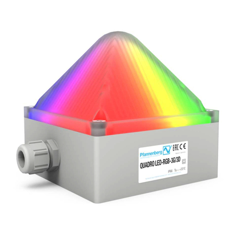
Pfannenberg Quadro LED-RGB-3G/3D Original instructions
Pfannenberg
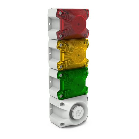
Pfannenberg PY L-S-TL User manual

Pfannenberg
Pfannenberg PY L-S-TL User manual

Pfannenberg
Pfannenberg Quadro LED-TL User manual

Pfannenberg
Pfannenberg Quadro LED-RGB-3G/3D User manual
Pfannenberg
Pfannenberg ABL User manual
Pfannenberg
Pfannenberg Quadro-LED HI Assembly instructions
Pfannenberg
Pfannenberg AB Assembly instructions
Pfannenberg
Pfannenberg PMF 2015-M Product guide
