2
Table of Contents
Table of Contents......................................2
Safety Information....................................2
Precautions............................................2
Warranty ...................................................2
2-Year Warranty .....................................2
Specifications...........................................3
Pre-Installation.........................................3
Planning Installation ..............................3
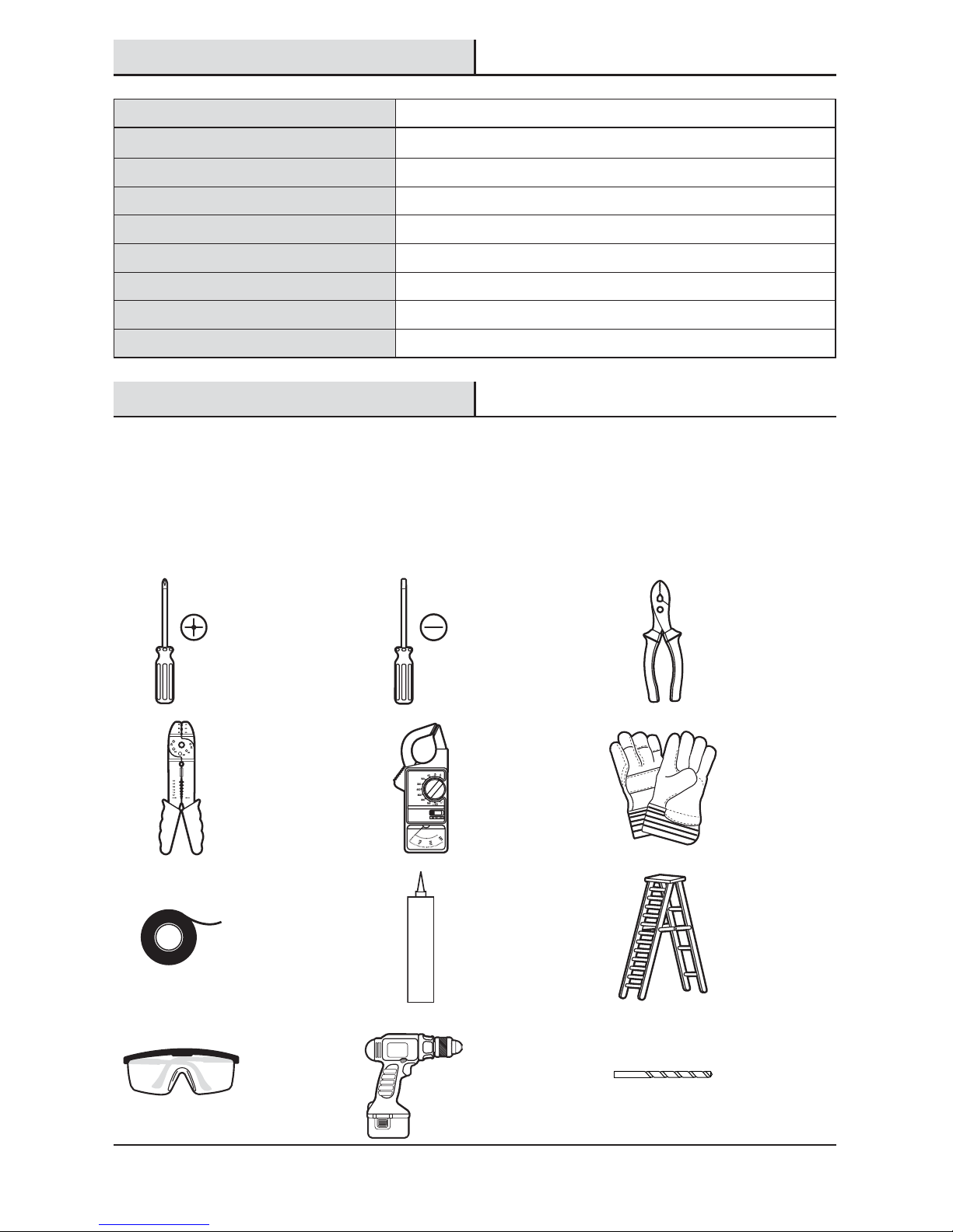
Tools Required .......................................3
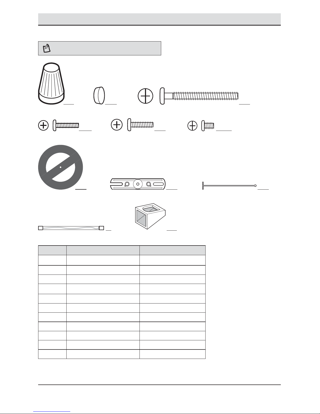
Hardware Included.................................4
Package Contents..................................5
Mounting Locations ...............................5
Installation................................................6
Operation...................................................9
Care and Cleaning ..................................12
Troubleshooting......................................12
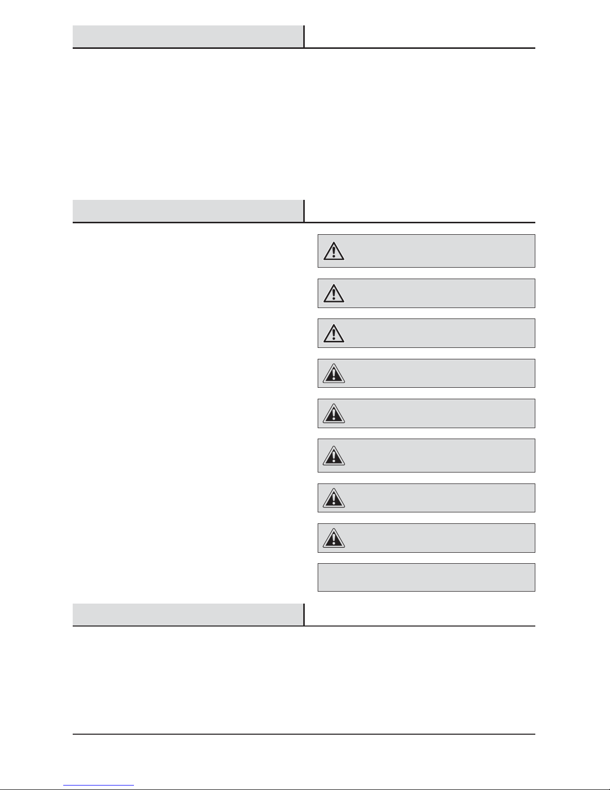
Safety Information
PRECAUTIONS
Please read and understand this entire manual before
attempting to assemble, install, or operate this light
xture.
This light xture requires 120-volts AC.
Some codes require installation by a qualied electrician.
This light xture must be properly grounded.
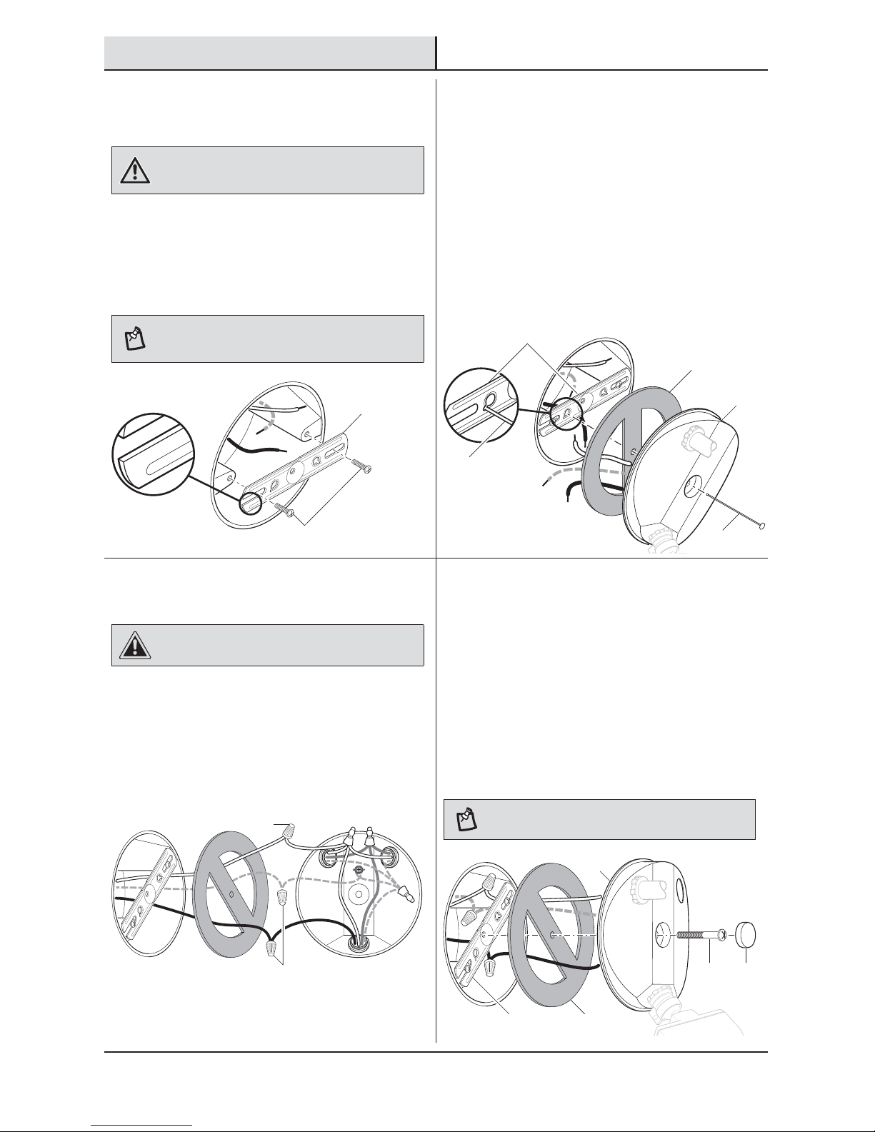
This light xture is intended for use with the enclosed
gasket and with a junction box marked for use in wet
locations.
Use a clean glove or cloth when handling the new bulb.
Use isopropyl (rubbing) alchohol to clean the bulb if it is
touched with bare hands.
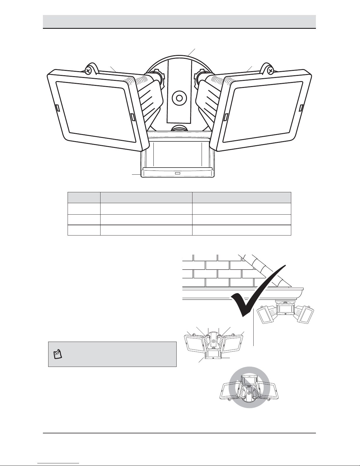
For proper operation, this light xture should be:
ƑInstalled outdoors to a wall or eaves
ƑInstalled 8 ft. (2.4 m) above the ground (If the light
xture is mounted higher than recommended,
aiming the sensor down will reduce the coverage
area.)
ƑDo not leave the “ON-TIME” switch in the “TEST”
position. The frequent ON/OFF cycling of the light
xture will reduce the life of the bulb
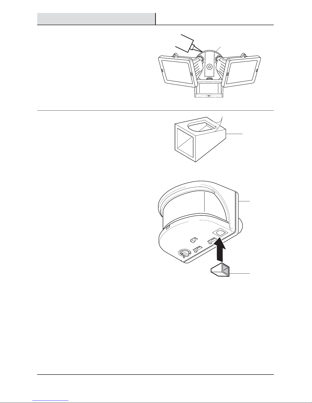
ƑUse only T3 150W (maximum), tungsten halogen
bulb (120 VAC)
WARNING: Turn the power off at the circuit breaker or
fuse. Place tape over the circuit breaker switch and verify
power is off at the light xture.
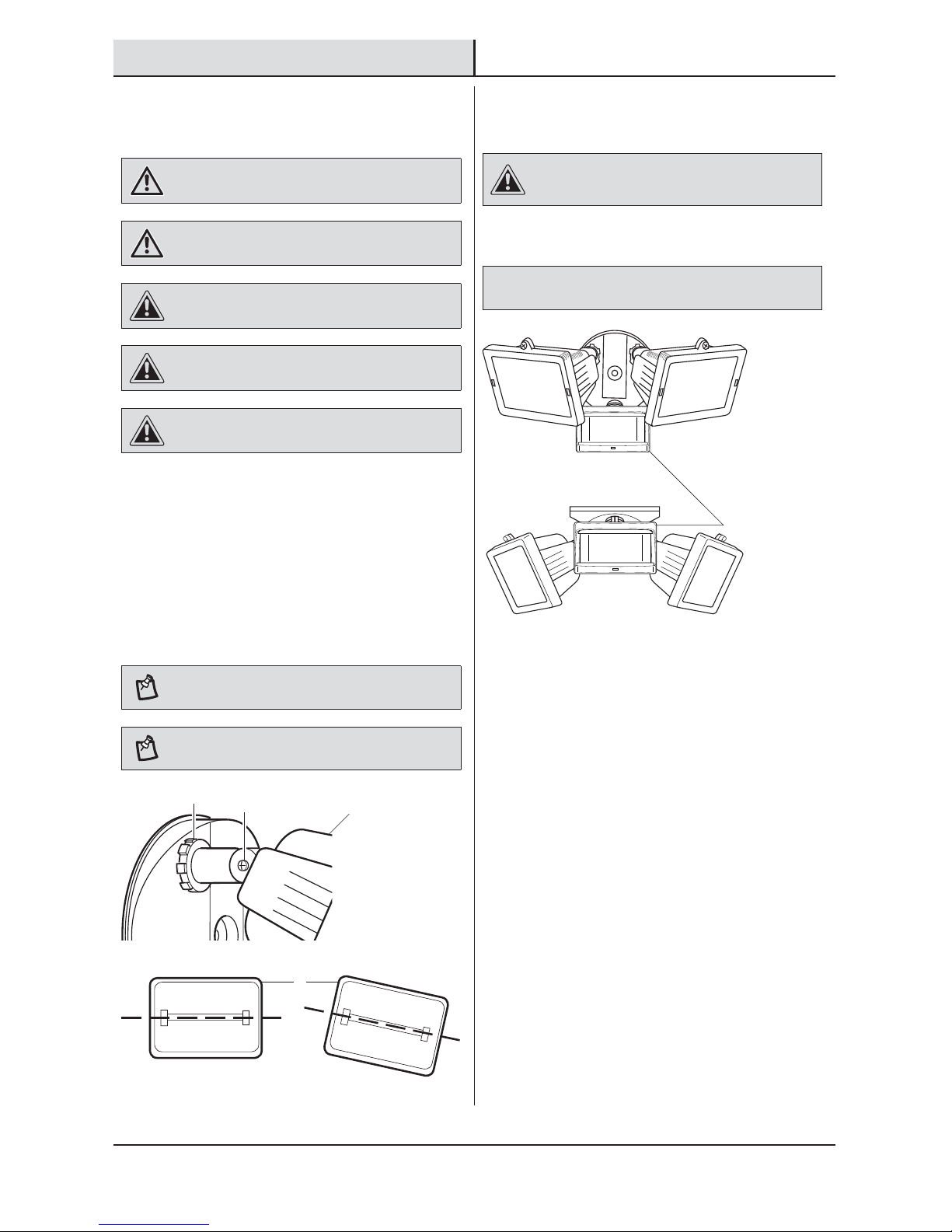
WARNING: Risk of re. Do not aim the bulb at a
combustible surface within 3 ft. (1 m).
WARNING: Risk of re. Keep the bulb at least 2in.
(51mm) from combustible materials.
CAUTION: Keep the motion sensor at least 1 in. (25 mm)
away from the bulb.
CAUTION: Keep the bulb holders 30° below horizontal to
avoid water damage and electrical shock.
CAUTION: To avoid water damage and the risk of
electrical shock, the motion sensor controls must be facing
the ground when the installation is complete.
CAUTION: Burn hazard. Allow the light xture and the
bulb to cool before touching.
CAUTION: Do not cut any wires with factory installed
wire connectors or remove the wire connectors.
NOTICE: Do not connect this light xture to a dimmer switch or
timer.
Warranty
2-YEAR WARRANTY
Contact the Customer Service Team at 1-866-308-3976 or visit www.homedepot.com.