ALIBI ALI-TP4028R User manual

1www.observint.com ALI-TP4028R_CQ
180607
Installation
Before installation:
• Make sure that the device is in good condition and all the assembly parts are included.
• Check the specication of the products for the installation environment.
• Make sure that the wall or the ceiling is strong enough to withstand 3 times the weight of the camera.
• To avoid re or shock hazard, use only UL listed power supplies. Verify that the power supply will
provide the rated voltage and wattage for the camera. See the Specications section.
During installation:
• Camera Lens: Handle the camera carefully to prevent scratching or soiling the lens. If the lens or IR
array shield becomes soiled, clean it only with approved products. See the Cleaning section.
• Power supply: Camera drop cable: The camera drop cable includes two connectors:
—Video BNC connector: For transmission of the video signal across a coax (75 Ω) extension
cable to an HD-TVI compatible recorder.
—Power connector: When applying power, observe the power polarity. See the picture to the
left for the connector polarity conguration.
Mounting the camera
An ALI-TP4028R camera can be mounted directly to a wall or ceiling, or with a junction box. The surface
should support at least three times the weight of the camera and junction box (if used). The video/power
drop cable from the camera can be routed either through mounting surface or through a cable channel in
the mounting base.
• Mounting the camera directly to a wall or ceiling
Typical wall mounting
NOTE
If mounting the camera on a wall, ensure that the cable channel in the mounting base is down.
If mounting the camera on a ceiling, orient the mounting base so that the cable channel is pointing
away from any source of water, dust, and other contaminates.
1. Using the drill template provided, mark the location of the screws that anchor the mounting base
to the mounting surface. See the note above. If you are routing the drop cable through mounting
surface, also mark the position of the hole for the drop cable.
2. Drill holes for the screws that anchor the base to the mounting surface. The mounting hardware
provided is appropriate for most surfaces. However, depending on the surface materials, more
appropriate fasteners may be required.
3. If routing the drop cable through the mounting surface, drill a 5/8” hole in the middle of the drill
template.
4. Route the drop cable through the hole in the mounting surface, or through the cable channel in the
mounting base, then attach the camera assembly to the surface using the appropriate fasteners.
5. Connect the camera drop cable to video and power extension cables as required.
6. Connect the other end of the video extension cable to an HD-TVI compatible video monitoring
device (QVR) digital video recorder.
NOTE
Drop cable connectors are not waterproof.
ALI-TP4028R 8MP HD-TVI
Outdoor Bullet Camera
Quick Installation Guide
The ALIBI ALI-TP4028R indoor/outdoor HD-TVI bullet cameras include a high sensitivity sensor with the
ability to send HD video across standard coaxial cable. This camera features:
• 8 MP Megapixel High Performance CMOS sensor
• Low light 0.003 Lux color illumination
• EXIR technology, 130 ft IR
• 2.8 mm lens with an 102˚eld of view
• Up the Coax (UTC) technology for OSD control
• -40° to 140°F temperature range
• IP67 weather rated housing
• Compatible with 8 MP HD-TVI recorders (HD-TVI DVR) such as the ALI-QVR5116H
• Can be installed with optional ALI-AJ6 junction box.
Camera body
Mounting base
Lens
Adjustable
mounting
bracket
ALI-TP4028R camera
Power connector
HD-TVI video BNC connector
CVBS video BNC connector
Camera drop cable connectors
What’s in the box
• Camera assembly
• Mounting hardware
• Drill template
• This instruction guide
What you need
To install the camera, you will need:
• 12 Vdc power source. See Specications for wattage requirement.
• Tools and additional fasteners (may be required) for mounting the camera
• Phillips #2 screwdriver
• Video and power extension cable
• HD-TVI video setup monitor (optional)

2www.observint.com
7. Connect the other end of the power extension cable to a 12 Vdc power source. Observe the
connector polarity of the cable shown in the photo on page 1 of this guide.
• Mounting the camera with a junction box
The ALI-AJ6 junction box is shown below. It can be attached to a wall or ceiling. Video and power
extension cables can be routed in through the opening in the back of the box or through the conduit
coupling, and attached to the camera drop cables inside the enclosure.
Front
Front
plate
Box
Conduit
coupling/
cable
channel
Back
“UP”
label
Holes for
mounting
screws (3) Holes for
mounting
base
screws (6)
To use the junction box:
1. Remove the ALI-AJ6 front plate from the box by removing the three screws (see above).
2. Attach the front plate to the camera mounting base using three screws. If the box will be wall
attached to a wall, ensure that the “UP” label on the mounting plate is at the top of the camera, and
the cable channel in the camera mounting base is toward the bottom of the camera.
3. Using the ALI-AJ6 box as a guide, mark and then drill three holes for the screws that will attach the
box to the wall or ceiling. If the extension cables will be routed into the box through the mounting
surface, also drill a hole for the extension cables.
4. Attach the box to a wall or ceiling with three screws. Ensure that the wall or ceiling will support at
least three times the weight of the camera with the junction box.
5. Route the video and power extension cables into the box.
6. Attach the video and power extension cable to the camera drop cables. Observe the polarity of the
power cable connector as shown on page 1 of this guide.
7. Attach the ALI-AJ6 front plate (with the camera) to the box.
Camera adjustments
1. Apply power to the camera.
2. Verify that video from the camera can be seen on the monitor.
3. While observing video from the camera, loosen the mounting bracket pan lock nut, point the
camera at your surveillance target, and then tighten the pan lock nut to hold the camera in position.
0° ~ 180°
0° ~ 360°
0° ~ 360°
Rotation: Use for
horizon line adjustment
Pan lock nut: loosen for pan,
tilt and rotation adjustments
Tilt: Use for
elevation
adjustment
Mounting bracket adjustment
Step 1. Open the OSD menu
The On Screen Display (OSD) provides conguration options for rening the performance of the camera.
It also can be used to block sensitive portions in the eld of view (Privacy). You can open the OSD menu
system from either the Recorder Live View display or through remote login to the ALIBI recorder.
Opening the OSD Menu through the recorder
To open the OSD menu on the recorder monitor:
1. Open the recorder Live View screen, and then click inside the screen where the PTZ camera video
image is displayed. See below.
2. Click the PTZ Control icon in the Quick Setting Toolbar. The PTZ camera Live View window will
expand to full screen and the pop-up window shown below will open.
Menu icon
3. In the PTZ Control panel pop-up window, click the Menu icon on the Conguration line.
4. Drag the PTZ Control window to a position where it doesn’t cover the OSD menu (such as the left
side).
NOTE
The PTZ Control window direction buttons and the Iris + and Iris - keys are used to navigate the
OSD menu and set conguration options in the camera. See “OSD Denitions: On-screen Display
(OSD) menus” on page 5.
Opening the OSD Menu through remote login to the recorder
To open the OSD menu during a remote login to the recorder:
1. After logging into the recorder, open the camera in a single Live View window.
© 2018 Observint Technologies. All rights reserved.

3www.observint.com © 2018 Observint Technologies. All rights reserved.
2. In the PTZ control panel, scroll down the Preset list to Preset95, click the entry to highlight it, and
then click the Call icon. See below. The OSD MAIN MENU screen will open.
PTZ control panelPreset95 Call icon
NOTE The PTZ control panel direction buttons and the Iris + and Iris - keys are used to navigate the OSD
menu and set conguration options in the camera.
OSD menu navigation
For the ALIBI Recorder: Navigation and settings in the OSD are made through direction keys and the Iris
+and Iris - buttons in the recorder PTZ Control panel. See below.
Direction keys
Click to open OSD menu
Iris+ Iris–
Iris+ Iris–
Direction keys
ALIBI QVR PTZ Control panel ALIBI QVR remote access PTZ control panel
For remote access to the ALIBI QVR: Navigation and settings in the OSD are made through direction
keys and the Iris + and Iris - buttons in the ALIBI QVR PTZ control panel. See above.
The function of the directional keys and Iris buttons are dened in the table below.
Keys Function
pMove up in the parameter list
qMove down in the parameter list.
tMove to previous page, eld, or move the camera left.
Keys Function
uMove to next page, eld, or move eld right.
Iris+ (OPEN) Set parameter value, or open sub-menu
Iris– (CLOSE) Cancel change of parameter.
OSD Denitions: On-screen Display (OSD) menus
After the camera is installed on a compatible recorder, you can open the OSD menu by clicking the PTZ
Control icon on the Quick Setting Toolbar.
To navigate the OSD menu and select options:
• Click the up/down ( p/ q) direction buttons to select the menu item.
• Click the left/right ( t/ u) direction buttons to adjust the value of the selected item.
• Click the Iris+ key to conrm a selection.
Video Format
You can set frame rate as 8 MP @ 12.5 fps, 8 MP @ 15 fps, 5 MP @ 20 fps, 4 MP @ 25 fps, 4 MP @ 30 fps,
1080p @ 25 fps, or 1080p @ 30 fps.
Language
The OSD supports English only.
Main Menu
Exposure submenu
Use the Exposure submenu to adjust the Brightness, Exposure Mode, AGC (Automatic Gain Control), and
Slow Shutter.
Brightness: Brightness refers to the average brightness of the image. You can set the brightness
value from 1 (darkest) to 10 (brightest).
Exposure Mode: You can set the Exposure Mode to Global, BLC, HLC, or WDR. Click the left/right
( t/ u) direction buttons to show your selection.

4www.observint.com © 2018 Observint Technologies. All rights reserved.
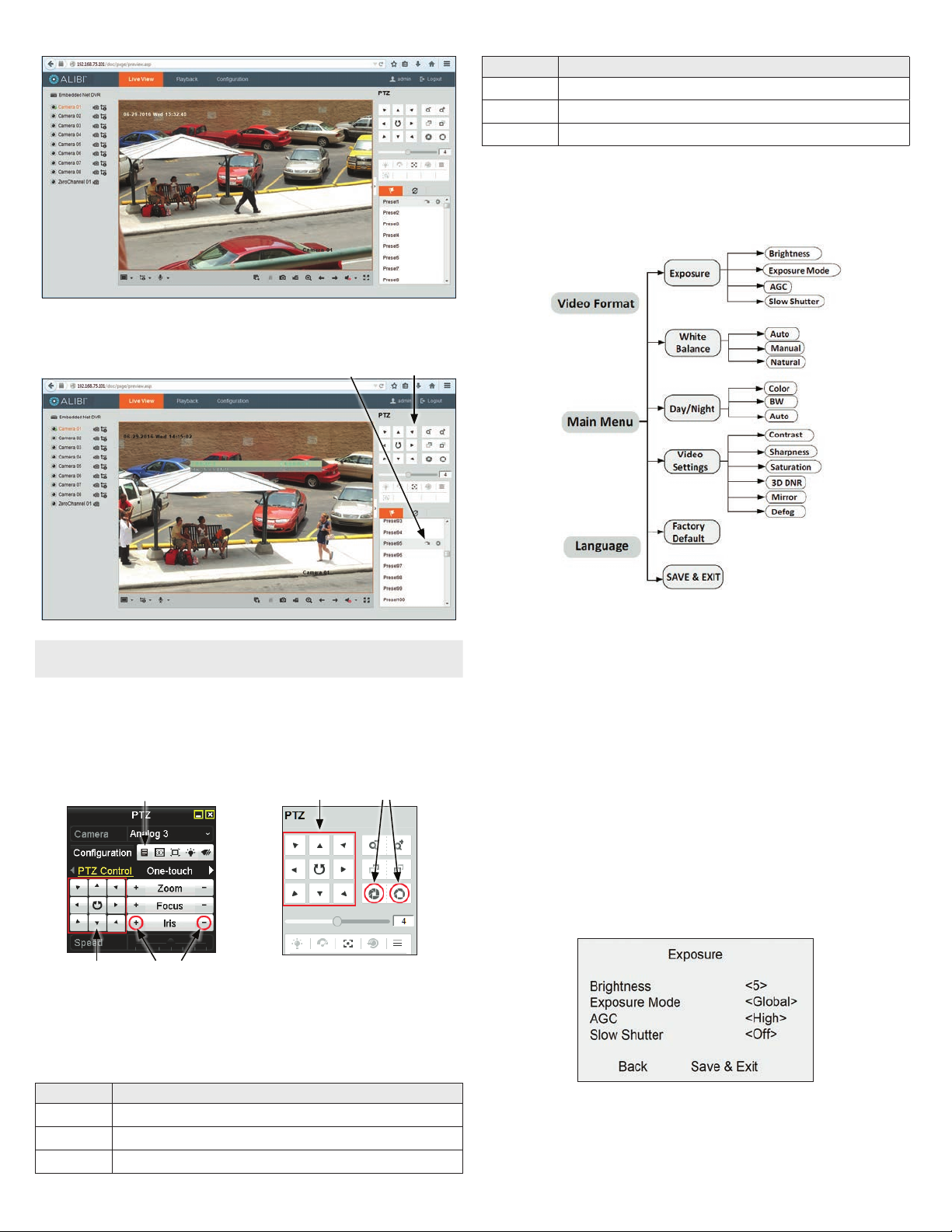
—Global: Global refers to the normal exposure mode which adjusts lighting distribution,
variations, and non-standard processing.
—BLC (Backlight Compensation): If the background is very bright compared to objects in front, BLC
brightens objects in the front to make them more visible.
—HLC (High Light Compensation): HLC masks strong light sources that excessively brighten areas
of the scene. This makes it possible to see details of the image that would normally be darkened
by the camera’s brightness compensation.
—WDR (Wide Dynamic Range): Use WDR to help the camera produce clear images even with
strong backlight. WDR balances the brightness level of the whole image and provides clear
images with details. When WDR is selected as the exposure mode, you can set it as low,
medium, high or o.
AGC (Automatic Gain Control): It optimizes the clarity of the image in poor light conditions. The AGC
level can be set as High, Medium, or Low. Select O to disable the AGC function. NOTE: The noise is
amplied when the AGC is on.
Slow Shutter: Slow Shutter increases the exposure time of a single frame, which makes the camera
more sensitive to light. Therefore, it can produce images even under low lux conditions. You can set
the Slow Shutter as O, x2, x4 under 8 MP @ 15 fps, or 8 MP @ 12.5 fps mode, and as O, x2, x4, x6,
x8, or x16 under other modes according to dierent light conditions.
WB (White Balance) submenu
White balance, the white rendition function of the camera, is to adjust the color temperature according to
the environment. It can remove unrealistic color casts in the image. You can set WB mode to Auto, Manual,
or Natural.
Auto: Under Auto mode, white balance is being adjusted automatically according to the color
temperature of the scene illumination.
Manual: Click Iris+ to enter the submenu, you can set the R Gain/B Gain value from 1 to 255 to adjust
the shades of red/blue color of the image.
Natural: Set the white balance as the Natural mode, when large part of the monitoring scene is
monochrome.
Day Night submenu
Color, BW (Black White), and AUTO are selectable for DAY and NIGHT switches.
Color: The image is colored in day mode all the time.
B/W: The image is black and white all the time, and the IR light turns on in the poor light conditions.
Auto: The image switches from color to B/W, or from B/W to color automatically according to the
light conditions. Click Iris+ to enter the submenu, you can turn on/o the IR Light and set the value of
Smart IR in this menu.
—IR Light: You can turn on/o the IR Light to meet the requirements of dierent circumstances.
—Smart IR: The Smart IR function is used to adjust the light to its most suitable intensity, and
prevent the image from over exposure. You can turn on/o this function.
—D/N Threshold (Day to Night Threshold): Use the Day to Night Threshold to control the
sensitivity of switching the day mode to the night mode. You can set the value from 1 (less
sensitive) to 9 (more sensitive).
—N/D Threshold (Night to Day Threshold): Use the Night to Day Threshold is used to control
the sensitivity of switching the night mode to the day mode. You can set the value from 1 (less
sensitive) to 9 (more sensitive).
Video Settings submenu
Move the cursor to Video Settings and click Iris+ to enter the submenu. Use this submenu to adjust the
Contrast, Sharpness, Saturation, 3D DNR, Mirror and Defog.
Contrast: This feature enhances the dierence in color and light between parts of an image. You can
set the Contrast value from 1 to 10.
Sharpness: Sharpness determines the amount of detail an imaging system can reproduce. You can
set the Sharpness value from 1 to 10.
Saturation: Use this option to change the color intensity. The value ranges from 1 to 10.
3D DNR (Digital Noise Reduction): Use the 3D DNR option to decrease video noise, especially
when capturing moving images in low light conditions, to produce a better image quality. You can set
the 3D DNR value from 1 to 10.
Mirror: O, H, V, and HV are selectable for mirror.
—O: The mirror function is disabled. H: The image ips 180° horizontally. V: The image ips 180°
vertically.
—H, V, HV: The image ips horizontally, vertically, or both horizontally and vertically.
Defog: It is used in special environments such as the foggy or rainy weather, or in high illumination
conditions, in which the image appears hazy. Enable the defog function can enhance the subtle details
to display clear images.
Factory Default
Click Iris+ to enter the submenu, and click OK to reset all the settings to the factory default. Click Cancel
to return to the menu without resetting the camera.
Save & Exit
Move the cursor to Save & Exit, and click Iris+ to save the settings and exit the menu. If new settings are
not saved, they remain in eect only until the camera is powered o or reset.
Specications
Camera
Image Sensor 8.29 MP CMOS image sensor
Signal system PAL / NTSC
Frame rate PAL: 8 MP @ 12.5 fps, 5 MP @ 20 fps, 4 MP @ 25 fps, 1080p @ 25 fps
NTSC: 8 MP @ 15 fps, 5 MP @ 20 fps, 4 MP @ 30 fps, 1080p @ 30 fps
Eective Pixels 3840 (H) × 2160 (V)
Min. illumination Color: 0.003 Lux @ (F1.2, AGC ON),
0 Lux with IR
Shutter Time PAL: 1/12.5 s to 1/10,000 s
NTSC: 1/15 s to 1/10,000 s
Slow shutter 16 times max.
Lens 2.8 mm with 102.2° horizontal FOV
Lens Mount M12
Day & Night IR cut lter
Angle Adjustment Pan: 0° ~ 360°; Tilt: 0° ~ 180°; Rotate: 0° ~ 360°
Synchronization Internal Synchronization
WDR (Wide Dynamic Range) 120 dB

5www.observint.com © 2018 Observint Technologies. All rights reserved.
Menu
AGC Supported
D/N Mode Auto / Color / BW (Black and White)
White Balance Auto / Manual / Natural
Privacy mask ON/OFF, 4 programmable privacy masks
BLC Supported
3D DNR (Digital Noise Reduction) Levels 1 to 10
Language English
Functions Contrast, Sharpness, Saturation, Mirror, Defog, HLC
Interface
TVI Video Output 1 HD-TVI output (75Ω / BNC)
CVBS Video Output 1 CVBS output (75Ω / BNC)
General
Operating Conditions -40°F −140°F (-40°C −60°C), Humidity 90% or less (non-condensing)
Power Supply 12 Vdc ± 25%
Power Consumption Max. 4.8 W
Protection Level IP67
Material Metal
IR Range Up to 130 ft (40 m)
Communication Up the coax (HD-TVI output)
Dimensions 2.28” × 2.40” × 6.42” (58 mm × 61 mm × 163 mm)
Weight 0.816 lb (370 g) aprox.
Cleaning
Clean the camera dome with an approved glass cleaning solution and a lint free cloth.
• Dust can be removed from the unit by wiping it with a soft damp cloth. To remove stains, gently rub
the surface with a soft cloth moistened with a mild detergent solution, then rinse and dry it with a
soft cloth. Do not use benzene, thinner or other chemical products on the camera assembly; these
may dissolve the paint and promote damage of the surfaces.
• Remove all foreign particles, such as plastic or rubber materials, attached to the camera housing.
These may cause damage to the surface over time.
Troubleshooting
Problem Possible Cause
Nothing appears on the screen - Check the power connection.
- Check the video signal cable connection to the monitor.
- Check QVR camera settings to verify the video resolution mode of the camera and
QVR match
The video image is dim or not clear. - If the camera lens is dirty, clean it with a soft, clean cloth.
- Adjust the monitor controls, if necessary.
- If the camera is facing a very strong light, change the camera position.
- Adjust the lens focus.
The screen is dark. - Adjust the contrast control of the monitor.
- If you have an intermediate device, set the impedance (75 Ω /Hi-Z) properly,
and check the cable connections.
The camera is not working properly
and the surface of the camera is hot.
- Verify that the camera is correctly connected to an appropriate regulated power
source.
The image on the monitor ickers - Make sure that the camera isn’t facing direct sunlight or uorescent light.
If necessary,change the camera position.
Table of contents
Other ALIBI Outdoor Camera manuals