3
OPERATION
1. Place sterilizer on a stable, heat tolerant
sur ace with access to appropriate electrical
power.
2. Remove the cover o the sterilizer by turning
the wing nuts in a counter-clockwise motion.
Always undo two opposite wing nuts at a time.
Turn cover and remove cover rom bottom. Next
remove inner container and inner container rack
rom sterilizer bottom (See Fig. A).
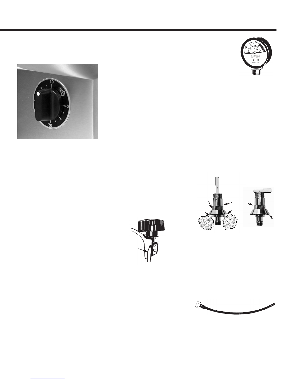
3. LUBRICATE METAL-TO-METAL SEAL Apply
lubrication to the entire beveled edge o the
bottom (See Fig. 1). We recommend using a high
temperature lubricant like high vacuum grease;
petroleum jelly may also be used as a substitute.
Only a thin ilm o lubrication is needed to
lubricate the metal-to-metal seal.
4. Place distilled or deionized water up to the
water line machined into the bottom o the
sterilizer. Water must be directly over the heating
element and NOT inside the inner container.
Next, place the inner container rack inside the
inner container with the lip side down (See Fig.
A). The purpose o the inner container rack is to
provide an air space at the bottom o the inner
container so that air may be evacuated and steam
is allowed to circulate reely throughout the entire
chamber.
5. With the inner container and inner container
rack out o the sterilizer place articles to be
sterilized inside the inner container on top o the
inner container rack. You may wish to place the
articles to be sterilized inside plastic bags speci -
ically designed or use inside steam sterilizers.
Arrange items so that steam may circulate reely
inside the chamber during the sterilization cycle.
Also, you can place a towel or cloth on top o the
items inside the container to absorb any moisture
that may drip down rom the cover onto the
items.
6. Check to see i your water level inside the
sterilizer is correct and then place loaded inner
container inside the sterilizer.
7. VERY IMPORTANT – make sure that the air
exhaust channel (located on the inside o the
inner container) is positioned on the right side o
the sterilizer. This is necessary so that when the
cover is placed on the unit you can guide the air
exhaust tube into the air exhaust tube channel
(See Fig. A).
8. Place the cover o the sterilizer making sure
that that index alignment arrow on the cover
aligns with the index line arrow on the side o the
bottom; AND that the air exhaust tube is inserted
into the air exhaust tube channel on the inner
container. With the cover aligned with the bottom
and the air exhaust tube inside the air exhaust
channel you may tighten the wing nuts on the
cover. Be sure to tighten wing nuts evenly,
always tightening down two opposite wing nuts
at one time. As you are tightening the wing nuts
be sure to maintain an even gap between the
cover and the bottom. Loosen or tighten the
wing nuts accordingly to maintain an even gap.
This will draw the cover down evenly and ensure
a proper seal. NEVER USE A WRENCH OR ANY
MECHANICAL DEVICE TO TIGHTEN WING
NUTS. NEVER HAMER OR STRIKE THE WING
NUTS OR COVER WHILE OPENING OR
CLOSING UNIT.
9. Plug power supply cord into the proper outlet
120V or 240V (re er to dial plate on ront o the
control box and note in the upper le t hand corner
i your unit is 120V or 240V). Next, turn the
on/o toggle switch to “on” position, the red pilot
light should be illuminated indicating that
electrical current is working and the heating
element is now operating. To increase heat, turn
the heat control knob in a clockwise direction; to
reduce heat, turn knob in a counter-clockwise
direction. Always maintain a close watch on the
pressure gauge and adjust heat accordingly.
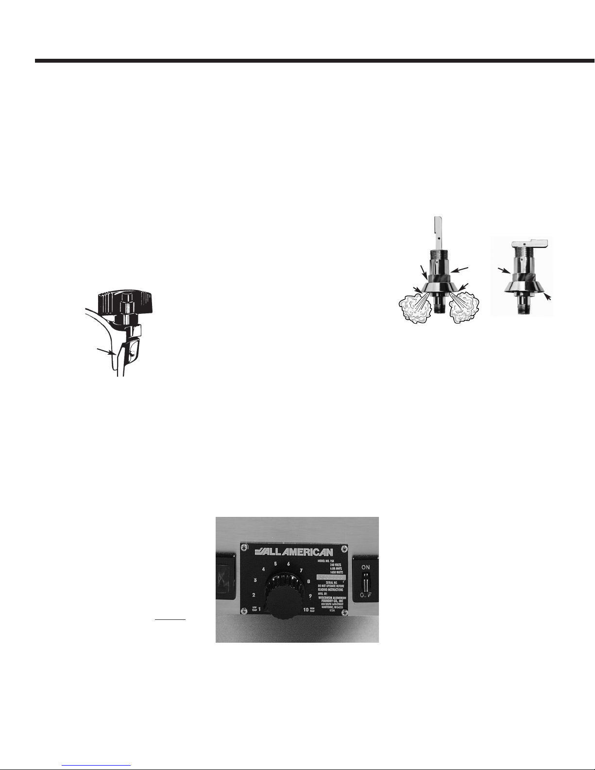
10. OPEN CONTROL VALVE (See Fig. 2) by
moving the lever into the upright position. Steam
generated by the sterilizer will be drawn rom the
bottom o the unit up through the air exhaust tube
and out the control valve. STEAM MUST
CONTINUOUSLY ESCAPE FROM THE CONTROL
VALVE FOR AT LEAST 5 MINUTES. Once this
has occurred, CLOSE THE VALVE AND LET
PRESSURE BUILD UNTIL THE GAUGE READS IN
THE “GREEN” STERILIZATION ZONE, which is
between 17 to 21 PSI or 121°C/250°F to
127°C/259°F. Once you have completed the
above, OPEN THE CONTROL VALVE A SECOND
TIME AND VENT THE CHAMBER FOR AN
ADDITIONAL 3 TO 5 MINUTES. Please Note that
the greatest reason or a sterilization ailure is
trapped air in the chamber o the sterilizer.
Trapped air may prevent the steam rom perme-
ating the contents to be sterilized.
11. Once the chamber is properly vented, close the
65k Control Value, then the sterilization cycle may
begin. Start timing the sterilization cycle when the
gauge needle is in the green sterilization zone on the
ace o the gauge between 17-21 PSI. We recommend
running a sterilization cycle o not less than 35 minutes
at a temperature o no less 121°C/250°F. Your
Fig. 1
Metal-to-metal seal
Apply lubricant here
Open control valve Closed control valve
Fig. 2 Fig. 3
Lever horizontal
or closed
Lever vertical
or open
steam escape
holes
steam escape
holes
valve body
de lector
de lector