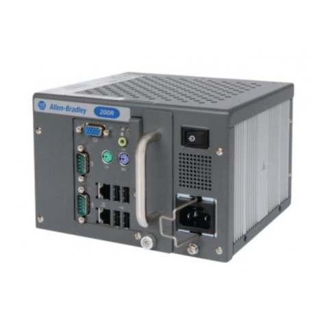
Allen-Bradley 6181X-NPXPDC User manual

Installation Instructions
Industrial Computers for Hazardous
Locations
Catalog Numbers 6181X-NPXPDC, 6181X-12TPXPDC
Topic Page
Important User Information 2
Environment and Enclosure Information 5
European Union Directive Compliance 3
Hazardous Locations 3
Hot Surfaces 4
Restricted Access Location 4
Environment and Enclosure Information 5
Product Options 7
Operating System 7
Multilingual User Interface CD Pack 8
Parts List 8
Required Tools 8
Installation Guidelines 9
Mounting Clearances 10
Product Dimensions 11
Install the Computer 12
Mount the Non-display Computer on a Wall 12
Mount the Display Computer in a Panel 13
Hardware Features 15
Connect Peripherals 16
Control Drawing - Class I Division 2 and Zone 2 Required Circuit
Parameters for USB Peripheral Devices 17
Apply Power 18
Connect to a Network 20
Component Replacement 21
Rear Cover 22
CompactFlash Card 23
PCI Add-in Card 25
Memory Module 26
RTC Battery 28
Ship or Transport the Product 29
Additional Resources 31

2Industrial Computers for Hazardous Locations
Rockwell Automation Publication 6181X-IN001C-EN-P - April 2011
Important User Information
Solid-state equipment has operational characteristics differing from those of electromechanical equipment.
Safety Guidelines for the Application, Installation and Maintenance of Solid State Controls (Publication
SGI-1.1 available from your local Rockwell Automation sales office or online at
http://www.rockwellautomation.com/literature/) describes some important differences between solid-state
equipment and hard-wired electromechanical devices. Because of this difference, and also because of the wide
variety of uses for solid-state equipment, all persons responsible for applying this equipment must satisfy
themselves that each intended application of this equipment is acceptable.
In no event will Rockwell Automation, Inc. be responsible or liable for indirect or consequential damages
resulting from the use or application of this equipment.
The examples and diagrams in this manual are included solely for illustrative purposes. Because of the many
variables and requirements associated with any particular installation, Rockwell Automation, Inc. cannot
assume responsibility or liability for actual use based on the examples and diagrams.
No patent liability is assumed by Rockwell Automation, Inc. with respect to use of information, circuits,
equipment, or software described in this manual.
Reproduction of the contents of this manual, in whole or in part, without written permission of Rockwell
Automation, Inc., is prohibited.
Throughout this manual, when necessary, we use notes to make you aware of safety considerations.
WARNING: Identifies information about practices or circumstances that can cause an
explosion in a hazardous environment, which may lead to personal injury or death, property
damage, or economic loss.
ATTENTION: Identifies information about practices or circumstances that can lead to personal
injury or death, property damage, or economic loss. Attentions help you identify a hazard, avoid
a hazard and recognize the consequences.
SHOCK HAZARD: Labels may be on or inside the equipment, for example, drive or motor, to
alert people that dangerous voltage may be present.
BURN HAZARD: Labels may be on or inside the equipment, for example, drive or motor, to
alert people that surfaces may reach dangerous temperatures.
IMPORTANT Identifies information that is critical for successful application and understanding of the
product.

Industrial Computers for Hazardous Locations 3
Rockwell Automation Publication 6181X-IN001C-EN-P - April 2011
European Union Directive Compliance
This product meets the European Union Directive requirements when installed within the
European Union or EEA regions and have the CE mark. A copy of the Declaration of
Conformity is available at the Rockwell Automation website http://www.ab.com under Product
Certification.
To comply with EN 55022 and EN 55024, use the following shielded or unshielded cable as
specified in this table.
Hazardous Locations
This equipment is suitable for these location categories.
ATTENTION: To comply with EN 55022 and EN 55024, all I/O cables
must be less than 30 m (98.42 ft). These cables must not exit the
building at any point and shall not directly connect to cables outside the
building.
Cable Type Required Attribute
LAN Shielded or Unshielded
USB Shielded
Serial RS-232 Shielded
DVI Shielded
VGA Shielded
DC Power Unshielded
Cat. No. Region Class/Division/Zone Rating Temperature
6181X-NPXPDC,
Non-display United
States Class I Division 2, Groups A, B, C, D T4
-20 °C ≤Ta≤70 °C(1)
(-4 °F < Ta< 158 °F)
Class I Zone 2, IIC, T4
Canada Class I Division 2, Groups A, B, C, D T4
Class I Zone 2, IIC, T4
Europe ATEX II 3 GD, Ex nA IIC Gc, Ex tc IIIC Dc
6181X-12TPXPDC,
Display United
States Class I Division 2, Groups A, B, C, D T4
-20 °C ≤ Ta ≤ 55 °C
(-4 °F < Ta < 131 °F) (Display side)
-20 °C ≤Ta≤70 °C
-4 °F < Ta< 158 °F) (Backside)(1)
(1) The entire 6181X-NPXPDC computer and the backside of the 6181X-12TPXPDC display are required to be mounted in a
restricted access location.
Class I Zone 2, IIC, T4
Canada Class I Division 2, Groups A, B, C, D T4
Class I Zone 2, IIC, T4
Europe ATEX II 3 GD, Ex nA nC IIC T4 Gc,
Ex tc IIIC T135 Dc

4Industrial Computers for Hazardous Locations
Rockwell Automation Publication 6181X-IN001C-EN-P - April 2011
The following statement applies when the equipment is used in a hazardous location.
Hot Surfaces
Restricted Access Location
Restricted access locations for the equipment should meet these conditions:
•Access can only be gained by service personnel or by users who have been instructed on
the reasons for the restrictions applied to a location and about any precautions that
should be taken.
•Access is through the use of a tool or a lock and key, or other means of security, and is
controlled by the authority responsible for the location.
Explosion Hazard
•Substitution of components may impair suitability for hazardous locations.
•Do not disconnect equipment unless power has been switched off and area
is known to be nonhazardous.
•Do not connect or disconnect components unless power has been switched
off.
•Peripheral equipment must be suitable for the location it is used in.
•In the U.S. all wiring must be in accordance with Class I, Division 2 wiring
methods of Article 501 of the National Electrical Code, and in accordance
with the authority having jurisdiction. Refer to control drawing information
in this document for allowable circuit parameters in Class I, Division 2
applications.
•In Canada all wiring must be in accordance with Section 18-1J2 of the
Canadian Electrical Code, and in accordance with the authority having
jurisdiction.
•For European Zone 2 applications transient limiting shall be provided in the
application that limits transient overvoltages to not more than 40% above
the applied voltage.
•For European Zone 2 applications, non-display computers must be mounted
completely within an enclosure rated IP54 minimum.
•For European Zone 2 (gases) applications computers with displays must be
mounted through the wall or door of an enclosure rated IP54 minimum. For
European Zone 22 (dusts) applications computers with displays must be
mounted through the wall or door of an enclosure rated IP6x minimum.
Computers with displays support enclosures rated up to IP66.
•For European Zone 2 applications do not use the USB ports unless the area
is known to be nonhazardous.
•These devices shall be properly connected to ground in the final application
by using the ground terminal screw provided on the computer chassis.
When used above 50 °C (122 °F) the backside of the 6181X-12TPXPDC
computer and the entire 6181X-NPXPDC computer must be installed in a
restricted access location.

Industrial Computers for Hazardous Locations 5
Rockwell Automation Publication 6181X-IN001C-EN-P - April 2011
Environment and Enclosure Information
Review the information on enclosures and environments before installing the product.
ATTENTION: This equipment is intended for use in a Pollution Degree 2
industrial environment, in overvoltage Category II applications (as defined in
IEC publication 60664-1), at altitudes up to 2000 m (6561 ft) without
derating.
This equipment is considered Group 1, Class A industrial equipment according
to IEC/CISPR Publication 11. Without appropriate precautions, there may be
potential difficulties ensuring electromagnetic compatibility in other
environments due to conducted as well as radiated disturbance.
This equipment is supplied as an open-type equipment. It must be mounted
within an enclosure that is suitably designed for those specific environmental
conditions that will be present and appropriately designed to prevent personal
injury resulting from accessibility to live parts. The interior of the enclosure
must be accessible only by the use of a tool. Subsequent sections of this
publication may contain additional information regarding specific enclosure
type ratings that are required to be complied with certain product safety
certifications.
All 6181X-12 display units ship with a gasketed bezel to meet specified NEMA,
UL Type, and IEC ratings only when mounted in a panel or enclosure with an
equivalent rating. Other sections of this publication contain additional
information regarding specific enclosure-type ratings required to comply with
certain product safety certifications.
See NEMA Standard publication 250, UL 50, and IEC publication 60529, as
applicable, for explanations of the degrees of protection provided by different
types of enclosure. Also, see the appropriate sections in this publication, as
well as the Allen-Bradley publication 1770-4.1, Industrial Automation Wiring
and Grounding Guidelines, for additional installation requirements pertaining
to this equipment.

6Industrial Computers for Hazardous Locations
Rockwell Automation Publication 6181X-IN001C-EN-P - April 2011
Environnements dangereux
Cet équipement peut être utilisé dans les environnements suivants :
•Classe I, Division 2, Groupes A, B, C et D .
•non dangereux.
La mise en garde suivante s’applique à une utilisation en environnement dangereux.
Les ordinateurs ont un code de température T4 (135°C) lorsqu’ils fonctionnent dans les
températures ambiantes maximales suivantes. Voir également le graphique Directives
d’installationen page 9de ce document.
•6181X-12……55°C en face avant de l’écran et 70°C en face arrière, en cas de montage
comme prévu au travers de la paroi d’un coffret.
•6181X-N……70°C au maximum, en cas de montage comme prévu à l’intérieur d’un
coffret.
N’installez pas l’ordinateur dans des environnements atmosphériques explosifs (par ex. du gaz)
dont la température d’inflammabilité est inférieure à 135°C.
ATTENTION: Danger d'explosion
•La substitution de composants peut rendre cet équipement impropre à une
utilisation en environnement dangereux.
•Ne pas déconnecter l’équipement sans s’être assuré que l’alimentation est
coupée et que l’environnement est classé non dangereux.
•Ne pas connecter ou déconnecter des composants sans s’être assuré que
l’alimentation est coupée.
•L’ensemble du câblage doit être conforme à la réglementation en vigueur dans
le pays où cet équipement est installé.
•L’équipement périphérique doit être adapté à l’environnement dans lequel il est
utilisé.
•Tout équipement utilisé en environnement dangereux doit être monté dans une
armoire fournissant une protection adaptée aux conditions d'utilisation
ambiantes et suffisante pour éviter toute blessure corporelle pouvant résulter
d'un contact direct avec des composants sous tension.

Industrial Computers for Hazardous Locations 7
Rockwell Automation Publication 6181X-IN001C-EN-P - April 2011
Product Options
This table summarizes the product options available for the industrial integrated display
computers.
This table summarizes the product accessories options available for the industrial integrated
display computers.
You can view a current list of accessories at this Rockwell Automation website
http://www.ab.com/industrialcomputers.
Operating System
The computers are shipped with the Windows XP Professional SP3 for Embedded Systems
installed and configured.
No operating system updates have been applied to the factory image beyond the service packs.
You can use the supplied Industrial Computer System Cloning CD to create and restore from a
recovery image. Refer to the Cloning Utility technical data, publication 6000-TD002, for
instructions.
Computers with solid state drives have been customized to accommodate the unique properties
of the solid state drive.
•No paging file.
•System restore is disabled.
•MUI languages are not pre-installed.
Computers with solid state drives do not contain a recovery partition. If additional drive space is
required, copy the I386 directory to external media; then delete the I386 directory from
C:\I386, which is approximately 400 MB.
To obtain the original factory image on bootable external-recovery media, which also includes
the I386 source directory, contact your local technical support center.
Cat. No. Series Display Size Touchscreen Package
6181X-NPXPDC F Non-display N/A Performance
6181X-12TPXPDC 12.1 in. Yes Performance
Cat. No. Description
6189X-MCLPS Mounting clips (10)
6189X-4GDDR2 4 GB RAM
6189V-CFSSD8GB CompactFlash card, 8 GB
6189V-CFSSD16GB CompactFlash card, 16 GB

8Industrial Computers for Hazardous Locations
Rockwell Automation Publication 6181X-IN001C-EN-P - April 2011
Multilingual User Interface CD Pack
The Microsoft Multilingual User-interface (MUI) CD Pack contains a collection of different
language sets that can be installed into the operating system. The primary language is English.
Languages pre-installed on computers with a hard disk drive include: Chinese, French, German,
Japanese, Italian, Spanish, and Portuguese.
MUI packs are available for all Windows XP operating systems and provide a localized start
menu and system icons support. The instructions for installing MUI languages on your
computer are supplied with the MUI CD Pack.
Parts List
Your computer is shipped with these items:
•Mounting hardware
•Panel cutout template, display computer only
•Installation instructions
•Production test report
•System CDs
–Accessory CD with Cloning Utility (red)
–System Support CD with Diagnostic Utility (green)
–Microsoft Multilingual User Interface (MUI) CD Pack (gray, 5 cd-pack), where
applicable
Required Tools
These tools are required for product installation:
•Panel cutout tools , display computer only
•#2 Phillips screwdriver
•Drill and M4 screw tap, non-display computer only
•Antistatic wrist strap (recommended)
Cat. No. Qty. Description
6181X-NPXPDC 4 M4 panhead screws with isolator grommets
6181X-12TPXPDC 10 Panel mounting clips

Industrial Computers for Hazardous Locations 9
Rockwell Automation Publication 6181X-IN001C-EN-P - April 2011
Installation Guidelines
Follow these guidelines to make sure your product provides safe and reliable service:
•The installation site must have sufficient power.
•The enclosure must allow sufficient space around air inlets and outlets to provide the
circulation necessary for cooling. Never allow air passages to become obstructed.
•The ambient air temperature must not exceed the maximum operating temperature.
Consider heat produced by other devices in the enclosure. You may need a user-supplied
fan, heat exchanger, or air conditioner to meet this condition.
•The humidity of the ambient air must not exceed specified limits. In very dry
environments, static charges build up readily. Proper grounding of the equipment helps
to reduce static discharges, which may cause shocks and damage electronic components.
•The enclosure or cover must remain in place at all times during operation. The cover
provides protection against high voltages inside the product and inhibits
radio-frequency emissions that might interfere with other equipment.
•The product cannot be tilted from vertical. Mount as shown below.
TIP Hot air rises. The temperature at the top of the enclosure is often higher than
the temperature in other parts of the enclosure, especially if air is not
circulating.
IMPORTANT The product can operate at a range of extremes. However, the life span of any
electronic device is shortened if you continuously operate the product at its
highest rated temperature.
55 °C (131 °F)
70 °C (158 °F)
70 °C (158 °F)
Restricted Access Location
Non-display Computer
Display Computer
6181X-12TPXPDC Display Computer 6181X-NPXPDC Non-display Computer
Up Up

10 Industrial Computers for Hazardous Locations
Rockwell Automation Publication 6181X-IN001C-EN-P - April 2011
Mounting Clearances
When selecting an installation site for the computers, be sure to allow adequate clearance on the
sides and rear of the computer for proper ventilation, cable connection, and hardware access.
Sufficient airflow throughout the system unit is required to maintain proper cooling. Clearance
should be enough to allow convenient installation or removal of peripheral components, such as
the CompactFlash card.
IMPORTANT Use adequate ventilation or other cooling methods to maintain the product
temperature at its specified rating.
Because of self-heating, do not operate the computer in an enclosure by using
the minimum clearances unless adequate ventilation or other cooling methods
are used to lower the temperature within the enclosure.
The minimum required enclosure size is 403 x 497 x 154 mm
(15.87 x 19.57 x 6.06 in.) (HxWxD).
Item Description Value
1 Top 50 mm (2 in.)
2 Back 50 mm (2 in.)
3 Left (for airflow) 50 mm (2 in.)
4 Right (for airflow and drive access) 127 mm (5 in.)
5 Bottom (for I/O port access and ventilation) 102 mm (4 in.)

Industrial Computers for Hazardous Locations 11
Rockwell Automation Publication 6181X-IN001C-EN-P - April 2011
Product Dimensions
Product dimensions for the computers are given in mm (in.).
Non-display Computer, Catalog Number 6181X-NPXPDC
Integrated Display Computer, Catalog Number 6181X-12TPXPDC
353.00 (13.90)
1.60 (0.06)
335.28 (13.20)
190.50 (7.5)
251.00 (9.88)
11.30 (0.44)
83.40 (3.28)
238.18 (9.37)
57.50 (2.26)
320.00 (12.60)
115.00 (4.53) 115.00 (4.53)
349.00 (13.74) 14.50 (0.57)
75.40 (2.97)
101.30 (3.99)
279.00 (10.98)
251.00 (9.88)

12 Industrial Computers for Hazardous Locations
Rockwell Automation Publication 6181X-IN001C-EN-P - April 2011
Install the Computer
The computers support these mounting options.
Mount the Non-display Computer on a Wall
Four mounting screws secure the non-display computer to a metal wall, such as a steel mounting
panel in an enclosure or equipment room.
Follow these steps to mount a non-display computer.
1. Disconnect power from the computer.
2. Attach the two of the supplied M4 panhead screws with grommets to the 1and 2screw
position as illustrated below.
3. Mount the computer on the wall and then attach the remaining two M4 panhead screws
with grommets to the 3and 4screw position.
4. Tighten the screws to a torque that is appropriate for the screw and wall.
Recommended torque in steel is 1.13…1.36 N•m (10…12 lb•in).
The illustration shows the location of the screw holes with the dimensions given in
mm (in.).
Cat. No. Computer Model Mounting Option
6181X-NPXPDC Non-display Wall mount
6181X-12TPXPDC(1)
(1) Display computers must be securely mounted by using all mounting clips.
Display Panel mount
IMPORTANT Do not mount the non-display computer on a horizontal surface.
335.28 (13.2)
190.50 (7.50)

Industrial Computers for Hazardous Locations 13
Rockwell Automation Publication 6181X-IN001C-EN-P - April 2011
Mount the Display Computer in a Panel
Mounting clips secure the 6181X-12TPXPDC display computer to the panel. Make sure to
mount the computer vertically.
Panel Mounting Guidelines
Observe these guidelines when installing the unit in a panel:
•Remove all electrical power from the panel before making the cutout.
•Confirm that there is adequate space behind the panel. For specific information refer to
Mounting Clearances on page 10.
•Cut supporting panel cutout to specifications before installation. Take precautions so
metal cuttings do not enter components already installed in panel.
Supporting panels must be of specified thickness to be sure of proper sealing against
water and dust and to provide proper support. The mounting hardware supplied
accommodates panel thickness between 14…8 GA or 1.6…4.2 mm (0.063…0.165 in.).
•Make sure the area around the panel cutout is clear.
Panel Cutout Dimensions
The 6181X-12TPXPDC display computer must be appropriately mounted in the panel cutout
specified below.
Follow these steps to mount the computer in a panel.
1. Remove power from the panel.
2. Cut an opening in the panel by using the appropriate panel cutout dimensions.
3. Place the computer in the panel cutout.
Failure to follow these guidelines may result in personal injury or damage to
the panel components.
Computer Cutout Dimensions (HxW), approx.
6181X-12TPXPDC 254.0 x 324.0 mm (10.0 x 12.76 in.)

14 Industrial Computers for Hazardous Locations
Rockwell Automation Publication 6181X-IN001C-EN-P - April 2011
4. Slide the mounting clips into the holes on the top, bottom, and sides of the computer.
5. Gradually tighten the clips, one at a time, around the bezel by using the specified
sequence starting with the center clips and continuing to the corner clips.
6. Tighten the mounting clips to a torque of 1.4 N•m (12 lb•in) by using the sequence in
step 5, being sure not to overtighten.
Repeat this process at least three times until the clips are properly torqued, making sure
the gasket is compressed uniformly against the panel.
ATTENTION: Tighten the mounting clips to the specified torque to provide a
proper seal and prevent damage to the product. Rockwell Automation assumes
no responsibility for water or chemical damage to the product or other
equipment within the enclosure because of improper installation.
1109
27
8
5
4
3
6

Industrial Computers for Hazardous Locations 15
Rockwell Automation Publication 6181X-IN001C-EN-P - April 2011
Hardware Features
The illustrations show the hardware features of the display industrial computers for hazardous
locations.
Front and Side Views, Catalog Number 6181X-12TPXPDC
Item Component
1 LCD panel, display model only
2 Storage drive bay
3 Rear cover

16 Industrial Computers for Hazardous Locations
Rockwell Automation Publication 6181X-IN001C-EN-P - April 2011
Bottom View, Catalog Number 6181X-12TPXPDC
Connect Peripherals
Connect the required peripherals, such as keyboard and mouse, to the corresponding I/O ports
on the bottom side of the computer. Refer to the illustration on the previous section for
connector locations.
Observe these guidelines when connecting peripherals to the computer:
•When connecting a device to the serial COM or DVI port, secure the connected device
with screws.
•The USB ports are covered by a hinged door.
–For more information about proper use of these ports refer to Hazardous Locations
statements on page 4.
Item Component
1 Serial COM ports, 2
2 Ethernet ports (RJ-45), 2
3 DVI-I port
4 PCI riser slot cover
5 Power switch
6 DC input terminal block
7 Functional ground screw
8 Hinged door covering the USB ports, 4(1)
9 External CompactFlash Type II card slot(1)
(1) This bottom side external CF slot and USB ports are functionally
hot-pluggable in an environment known to be non-hazardous. For more
information about proper use of these ports refer to
Hazardous Locations statements on page 4.

Industrial Computers for Hazardous Locations 17
Rockwell Automation Publication 6181X-IN001C-EN-P - April 2011
Control Drawing - Class I Division 2 and Zone 2 Required Circuit
Parameters for USB Peripheral Devices
The following control drawing is provided in accordance with the National Electrical Code,
Article 500 (Class I, Zone 2, Group IIB and Class I, Division 2, Groups A, B, C and D).
Parameter Value Parameter Definition
V oc (USB) 5.25V DC Open circuit voltage of each host USB port.
The maximum applied voltage rating, Vmax (peripheral), of each peripheral
device shall be greater than or equal to Voc (USB).
Vmax (peripheral) ≥VOC (USB), as appropriate
Isc (USB) 950 mA Maximum output current of each host USB port.
The maximum current, I max (peripheral), to which each USB peripheral
device can be subjected shall be greater than or equal to Isc (USB) .
Imax (peripheral) ≥Isc (USB)
C a (USB) 20 µF This value is the maximum total capacitance that can be connected to
each USB port. The total capacitance of each USB peripheral and its
cable must not exceed the indicated value.
The maximum total capacitance, Ci (peripheral), and cable capacitance of
each separate USB peripheral device shall be less than or equal to Ca
(USB).
Ci ( peripheral) + Ccable ≤Ca (USB)
L a (USB) 3.11 µH This value is the maximum total inductance that can be connected to
each USB port. The total inductance of each peripheral device and its
cable must not exceed the indicated value.
The maximum total inductance, Li (peripheral), and cable inductance of
each separate USB peripheral device shall be less than or equal to
La (USB).
Li (peripheral) + Lcable ≤La (USB)
USB Port USB Peripheral Device
6181X Host Product
Associated Nonincendive
Field Wiring Apparatus
Nonincendive Field
Wiring Apparatus

18 Industrial Computers for Hazardous Locations
Rockwell Automation Publication 6181X-IN001C-EN-P - April 2011
Application Information
The circuit parameters of associated field-wired apparatus for use in hazardous locations shall be
coordinated with the host product such that their combination remains nonincendive. The
6181X computers and the USB peripheral devices shall be treated in this manner.
The circuit parameters of the 6181X computers’ USB ports are indicated in the previous table.
The 6181X computers provides four separately powered USB ports.
The USB peripheral devices and their associated cabling shall have circuit parameters with the
limits given in the Control Drawing - Class I Division 2 and Zone 2 Required Circuit
Parameters for USB Peripheral Devices section table for them to remain nonincendive when
used with the 6181X computers’ USB ports.
For the comparison of C a(USB), use the capacitance of each individual connected USB peripheral
device, C i(peripheral), and its associated cable, C cable.
If cable capacitance and inductance are not known, the following values may be used:
Ccable = 197 µF/m (60 pF/ft)
Lcable = 0.7 µH/m (0.20 µH/ft)
Apply Power
Both the display and non-display computers have a DC input terminal block for connecting to a
18…32V DC power source.
The DC power option supports operation from safety extra-low voltage (SELV) power source.
The power supply is internally protected against reverse polarity.
A functional ground connection is required for EMC compliance.
ATTENTION: The computer circuit should have its own disconnect. Use an
uninterruptible power source (UPS) to protect against unexpected power failure
or power surges.
Always shut down the operating system before removing power to minimize
performance degradation and operating system failures.
ATTENTION: Use an SELV isolated and ungrounded power supply as input
power to the computer. This power source provides protection so that under
normal and single fault conditions, the voltage between the conductors and
Functional Earth/Protective Earth does not exceed a safe value.

Industrial Computers for Hazardous Locations 19
Rockwell Automation Publication 6181X-IN001C-EN-P - April 2011
Follow these steps to connect the computer to a DC power source.
1. Verify the main power switch or breaker is off.
2. Verify that the DC power wires meet these requirements:
–Material: Stranded copper
–Wire gauge: 14…18 AWG
3. Secure the DC power wires to the terminal block screws.
Tighten the terminal to a torque of 0.687 N•m (6.1 lb•in).
4. Secure the ground wire by using a ring style connector to the functional earth terminal
screw.
Tighten to a torque of 1.47 N•m (13 lb•in).
5. Apply 18…32V DC power to the computer.
IMPORTANT When using the functional ground screw, connect the product to earth ground
by using a 1.5 mm2(16 AWG) or larger external wire.
6181X-12TPXPDC Display Computer Shown
-V +V -V +V
6181X-NPXPDC
Non-display Computer 6181X-12TPXPDC
Display Computer

20 Industrial Computers for Hazardous Locations
Rockwell Automation Publication 6181X-IN001C-EN-P - April 2011
Connect to a Network
The computers have two Gigabit LAN ports. The computers connect to an Ethernet network by
using CAT5 or CAT5E twisted-pair Ethernet cabling with RJ-45 connectors.
ATTENTION: When connecting a LAN cable, make sure the cable is fully
inserted in the LAN port and that the latch is engaged. Failure to do so could
result in an electrical arc that can cause an explosion in a hazardous location.
IMPORTANT To prevent performance degradation of Ethernet communication, do not subject
the computer or cables to extreme radiation or conducted high-frequency noise.
Proper cable routing and power conditioning is required to be sure of reliable
Ethernet communication in an industrial environment. Rockwell Automation
recommends that you route all Ethernet cabling through dedicated metal
conduits. Installing ferrite bead filters at the cable ends may also improve
reliability.
6181X-12TPXPDC
Display Computer
6181X-NPXPDC
Non-display Computer
Other manuals for 6181X-NPXPDC
1
This manual suits for next models
1
Table of contents
Other Allen-Bradley Industrial PC manuals

Allen-Bradley
Allen-Bradley 6181 User manual

Allen-Bradley
Allen-Bradley 6180P-12KSXP User manual

Allen-Bradley
Allen-Bradley 6155R-NSXP User manual

Allen-Bradley
Allen-Bradley 6177R-MM User manual

Allen-Bradley
Allen-Bradley 6189V-35HDD1TB User manual

Allen-Bradley
Allen-Bradley 6180 User manual

Allen-Bradley
Allen-Bradley H Series User manual