GE PACSystems RXi Box IPC User manual

GE
Intelligent Platforms
Industrial Computer Products
PACSystems*
RXi Box IPC
User's Manual, GFK-2785C
May 2014

GFK-2785C PACSystems* RXi Box IPC
GFL-002
Warnings, Cautions and Notes
as Used in this Publication
Warning
Warning notices are used in this publication to emphasize that hazardous voltages, currents,
temperatures, or other conditions that could cause personal injury exist in this equipment or may
be associated with its use.
In situations where inattention could cause either personal injury or damage to equipment, a
Warning notice is used.
Caution
Caution notices are used where equipment might be damaged if care is not taken.
Note: Notes merely call attention to information that is especially significant to understanding
and operating the equipment.
This document is based on information available at the time of its publication. While efforts have
been made to be accurate, the information contained herein does not purport to cover all details
or variations in hardware or software, nor to provide for every possible contingency in connection
with installation, operation, or maintenance. Features may be described herein which are not
present in all hardware and software systems. GE Intelligent Platforms assumes no obligation of
notice to holders of this document with respect to changes subsequently made.
GE Intelligent Platforms makes no representation or warranty, expressed, implied, or statutory with
respect to, and assumes no responsibility for the accuracy, completeness, sufficiency, or usefulness
of the information contained herein. No warranties of merchantability or fitness for purpose
shall apply.
* indicates a trademark of GE Intelligent Platforms, Inc. and/or its affiliates. All other trademarks
are the property of their respective owners.
©Copyright 2014 GE Intelligent Platforms, Inc.
All Rights Reserved

Contact Information
ii PACSystems* RXi Box IPC GFK-2785C
If you purchased this product through an Authorized Channel Partner, please contact the seller directly.
General Contact Information
Online technical support and GlobalCare
http://support.ge-ip.com
Additional information
http://www.ge-ip.com/
Solution Provider
solutionprov[email protected]
Technical Support
If you have technical problems that cannot be resolved with the information in this guide, please contact us by
telephone or email, or on the web at http://support.ge-ip.com
Americas
Online Technical Support
http://support.ge-ip.com
Phone
1-800-433-2682
International Americas Direct Dial
1-780-420-2010 (if toll free 800 option is unavailable)
Technical Support Email
support.ip@ge.com
Customer Care Email
customercare.[email protected]
Primary language of support
English
Europe, the Middle East, and Africa
Online Technical Support
http://support.ge-ip.com
Phone
+800-1-433-2682
EMEA Direct Dial
+420-23-901-5850 (if toll free 800 option is unavailable or dialing
from a mobile telephone)
Technical Support Email
support.emea.[email protected]
Customer Care Email
customercare.[email protected]
Primary languages of support
English, French, German, Italian, Czech, Spanish
Asia Pacific
Online Technical Support
http://support.ge-ip.com
Phone
+86-400-820-8208
+86-21-3217-4826 (India, Indonesia, and Pakistan)
Technical Support Email
Customer Care Email
customercare.a[email protected]

Contents
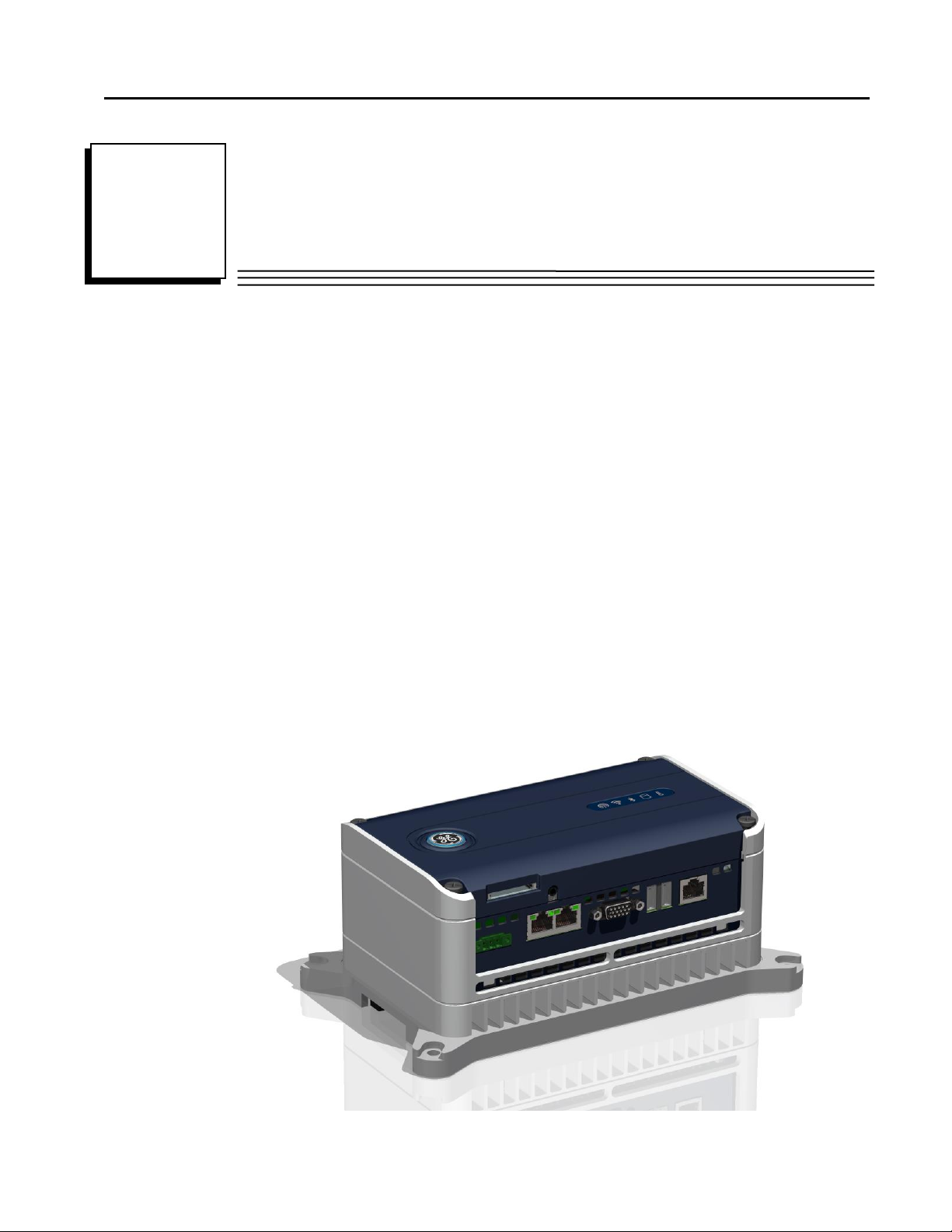
GFK-2785C PACSystems* RXi Box IPC iii
Contents
Introduction........................................................................................................................................1
Specifications .................................................................................................................................2
General Specifications................................................................................................................2
Environmental Specifications.....................................................................................................3
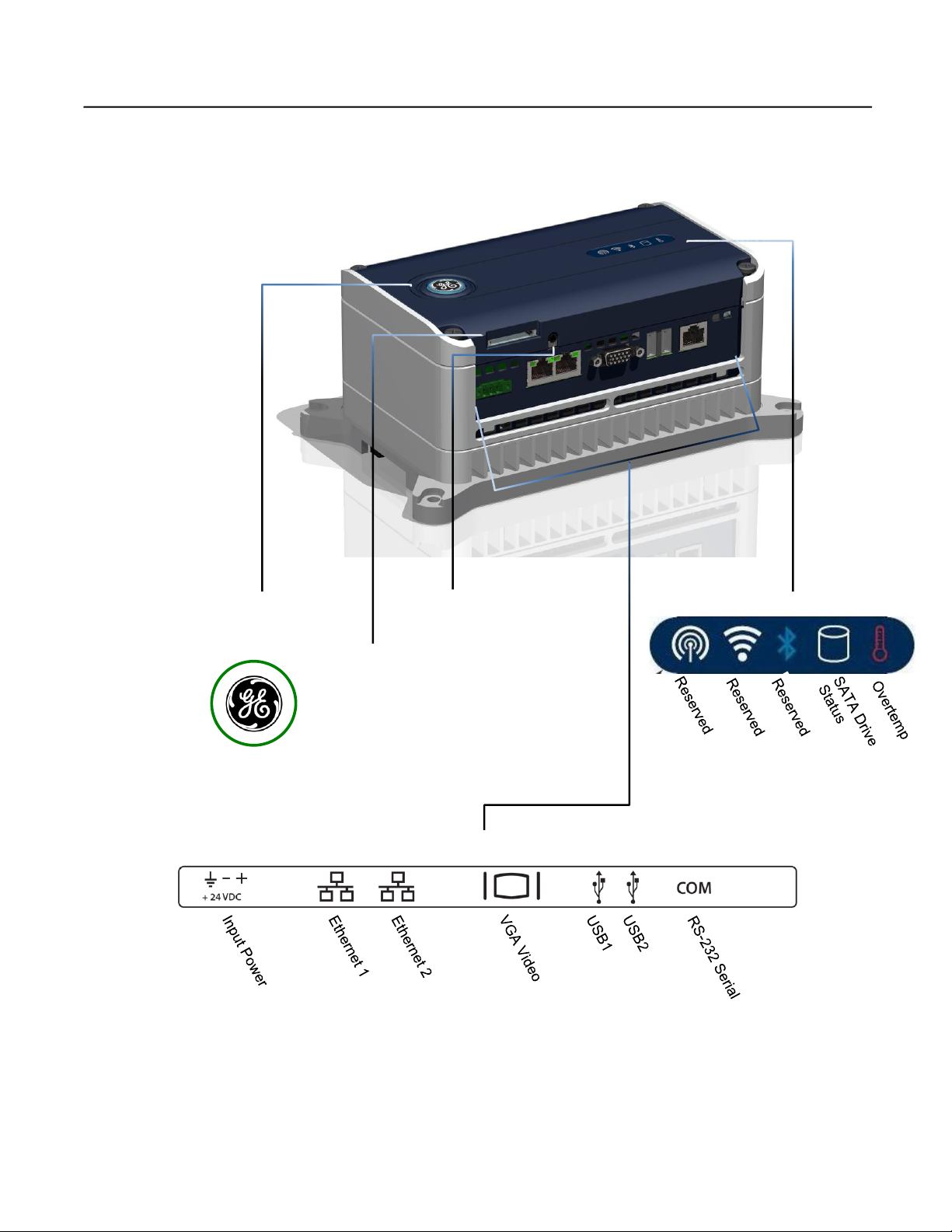
RXi Box IPC User Features ...........................................................................................................4
Power On/Off Switch and Status Indicator Operation................................................................5
IPC Status Indicators Operation.................................................................................................5
Ethernet Port LEDs Operation....................................................................................................5
Resume Power Mode Operation.................................................................................................6
Sleep Mode Setting Options and Ring LED Status Indicator Operation....................................6
Unpacking and Initial Startup.............................................................................................................7
Unpacking and Inspection..............................................................................................................7
Initial Startup..................................................................................................................................8
Configuring Ethernet Network Communications...........................................................................9
Pinging TCP/IP Ethernet Interfaces on the Network..................................................................9
Shutting Down the Computer.......................................................................................................10
Disabling Operating System Shutdown (ICRXIBN7xxxxx Models)...........................................10
Hardware Installation .......................................................................................................................11
Installation Guidelines..................................................................................................................11
Grounding.................................................................................................................................12
Mounting Orientation...............................................................................................................12
Dimensions and Clearances for Installation .............................................................................13
Mounting Procedures ...................................................................................................................14
Mounting the IPC on a DIN Rail..............................................................................................14
Mounting the IPC on a Panel Using a Backplate .....................................................................18
Mounting the IPC Directly on a Panel......................................................................................19
Replacing the RTC Battery ..........................................................................................................21
Disabling the Off Switch..............................................................................................................23
Connectors and Cabling ...................................................................................................................25
Input Power ..................................................................................................................................25
Ethernet Communication Ports.....................................................................................................26
Serial Communication Port ..........................................................................................................27
USB Ports.....................................................................................................................................27
Video Output Port ........................................................................................................................28
SD (Secure Digital) Card Slot......................................................................................................28
Audio Jack....................................................................................................................................28
System Recovery..............................................................................................................................29
Recovering from a Drive Failure (ICRXIBN7x000x Models only).............................................29
Recovering from a Drive Failure (ICRXIBN7x001x Models only).............................................30
Recovering from an Overtemperature Shutdown (All Models) ...................................................33
Product Certifications and Installation Guidelines for Conformance...............................................35
Agency Approvals........................................................................................................................36
Standards Overview .....................................................................................................................37
EMC Emissions and Immunity Specifications.........................................................................37
Government Regulations..............................................................................................................38
Index.................................................................................................................................................39


GFK-2785C PACSystems* RXi Box IPC 1
Introduction
The PACSystems RXi family of industrial computers provides an advanced, high-performance
control and computing platform. The PACSystems RXi Box IPC delivers the flexibility of a PC with
the industrial ruggedness of traditional automation controllers.
Built with an open and scalable architecture, the RXi platform enables easy connectivity and
allows you to maximize application reusability—supporting your current and future needs for
business growth.
These small form-factor industrial PCs provide a number of features to support computing
applications in demanding environments.
■Dual core 1.0 GHz VIA processor
■Multiple Gigabit Ethernet interfaces provide network implementation flexibility.
■Built-in Data Storage –Internal disks provide highly reliable local long-term data retention.
■USB and SD Card interfaces enable program loading, serial communications and removable
data storage via standard devices.
1
Chapter

Introduction
2 PACSystems* RXi Box IPC GFK-2785C
Specifications
Part numbers:
ICRXIBN7E000A
RXi Box IPC with Embedded 32GB mSATA SSD and Windows 7 Professional,
SP1 or later operating system
ICRXIBN7E001A
RXi Box IPC with Embedded 32GB mSATA SSD and Windows Embedded
Standard 7
ICRXIBN7M000A
RXi Box IPC with 250GB Magnetic SATA Hard Drive and Windows 7
Professional, SP1 or later operating system
ICRXIBN7M001A
RXi Box IPC with 250GB Magnetic SATA Hard Drive and Windows Embedded
Standard 7
ICRXIBN0E000A
RXi Box IPC with Embedded 32GB mSATA SSD
ICRXIBN0M000A
RXi Box IPC with 250GB Magnetic SATA Hard Drive
ICRXIACCBPL
Optional Backplate for DIN rail mounting
IC690ACC001
Real Time Clock (RTC) battery, included with IPC
General Specifications
Dimensions
IPC:
191.8mm x 115.6mm x 81.3mm
(7.55 in x 4.55 in. x 3.2 in)
Backplate:
226 mm x 137 mm x 12 mm
(8.90 in. x 5.39 in. x 0.47 in.)
Weight:
IPC without Backplate
1.814 Kg (4 lbs)
Backplate
0.454 Kg (1 lb)
Processor
1.0 GHz VIA Eden dual core processor
RAM
4GB DDR3
Floating point
64 bit
Non-volatile storage
32GB mSATA SSD or 250GB SATA drive
Non-volatile storage (NVS) can retain data indefinitely without loss of
data integrity.
Time of day clock (RTC)
accuracy
Maximum drift of ±2 seconds/day at 25°C.
Elapsed time clock (internal
timing) accuracy
± 0.01% maximum
Video
Standard 15-pin VGA connector
Maintenance ports†
Two Type A USB 2.0
SD standard card slot
Dual function Audio out/Microphone in jack (3.5mm four-pin TRRS)
Power requirements
1.8 A at 24 VDC (18–32 VDC)
LPS or Class 2 power supply required.
Serial Communications
One RS-232 RJ-45 port
ICRXIBN7x000A-CA versions and earlier
COM2
ICRXIBN7x001A
COM1
Ethernet Communications
Two Ethernet (10, 100, 1000 Mbit/s) RJ-45 ports
†Intended only for temporary connection.

Introduction
GFK-2785C PACSystems* RXi Box IPC 3
Environmental Specifications
Note: The Box IPC shall be installed in a location that is not exposed to corrosive gases or
liquids, rain, or direct sunlight, and that meets the environmental specifications listed
below.
Vibration1
IEC60068-2-6
10 - 57 Hz, 0.006 in. displacement peak-peak
57 - 500 Hz, 1.0 g acceleration
Shock
IEC60068-2-27
15 g, 11ms
Ambient Operating Temperature2
ICRXIBNxE00xA
ICRXIBNxM00xA
-25C to +65C: [inlet] (-13° F to 149°F)
0C to +40C: [inlet] (32° F to 104°F)
Storage Temperature
-40C to +85C (-40°F to 185°F)
Humidity
5% to 95%, non-condensing
Environment
UL60950-1
Pollution Degree 2
Altitude
UL60950-1
0–2000 m
1 Applies only to IPCs with solid state hard drive (ICRXIBNxE00xA).
2 For ambient temperatures greater than 50°C (122°F), the unit must be installed in a
restricted access area, as defined below.
Warning
If the Box IPC is operating in ambient temperatures greater than 50°C (122°F),
its exterior temperatures may be too hot to touch safely. To avoid burn
hazards, the unit must be installed in a restricted access area, as defined by:
Access can only be gained by service persons or by users who have been instructed
about the reasons for the restrictions applied to the location and about any
precautions that shall be taken; and
Access is through the use of a tool or lock and key, or other means of security, and
is controlled by the authority responsible for the location.
Pollution Degree 2
A Pollution Degree 2 environment as defined by UL60950-1:
Pollution Degree 2 applies where there is only non-conductive pollution that might
temporarily become conductive due to occasional condensation.
Note: For additional product standards and agency approvals, refer to Appendix A.

Introduction
4 PACSystems* RXi Box IPC GFK-2785C
RXi Box IPC User Features
Power On/Off
Switch and Status
Indicator
Indicators
SD Card Slot
Audio
Connector
Connectors
Blue, blinking –Booting
Blue, slow fade –S3 Sleep
Green, solid –Running
Red, solid –Fault

Introduction
GFK-2785C PACSystems* RXi Box IPC 5
Power On/Off Switch and Status Indicator Operation
Normal Operation†
Action
Power up the IPC
Press and hold the button for at least ½ second.
If powering up from a no-power state, the ring LED blinks blue while the IPC is
booting and is solid green when the IPC is up and running.
For ICRXIBN7x000A-CA or earlier only: If the system has been shut down, but
power has not been cycled, the ring LED immediately turns solid green.
For all other versions the ring LED blinks blue for 40 seconds before changing to
solid green.
Shut down the IPC
Press and hold the button briefly (between 100ms and 4 seconds).
The ring LED stays green while the IPC is shutting down and then turns off when
the IPC is powered down.
Sleep Mode
The default BIOS settings when shipped from the factory are:
“Enable Hibernation”is disabled
ACPI Sleep State is “S1 (CPU Stop Clock)”
The default settings send IPC to sleep state S1.
ICRXIBN7x000A: The ring LED stays green while the IPC is in Sleep State S1.
The ring LED turns off while the IPC is in Sleep State S3
ICRXIBN7x001A: The ring LED stays green while the IPC is in Sleep State S1.
The ring LED fades blue while the IPC is in Sleep State S3.
Forced Shut down
Caution: Use this option only if the operating system is non-responsive:
Press the button for at least 4 seconds.
The ring LED turns off.
†The ring LED displays solid red to indicate a fault, including Overtemp condition.
IPC Status Indicators Operation
Indicator
State
Description
SATA Drive Status
White, blinking
Read/write access on SATA drive.
Overtemp
Red, solid
The IPC’s internal temperature has exceeded the
maximum allowable value.
To recover, let the IPC cool, then press the Power On/Off
switch.
Ethernet Port LEDs Operation
Each Ethernet port has two LED indicators, ACTIVITY and LINK.
LED
LED State
Operating State
ACTIVITY
Blinking, Green
Traffic is detected at the port.
LINK
On, Green
The link is operational.

Introduction
6 PACSystems* RXi Box IPC GFK-2785C
Resume Power Mode Operation
UEFI Setting for “Resume
after Power loss”
ICRXIBN7x001A RXi Box IPC Behavior
[On - default]
After restoring power, the unit will always restart without having to
press the button.
[Off]
After restoring power, you will always have to press the button to
start the unit.
[Last state]
The chipset remembers the last state. After restoring power:
-A clean Win7 shutdown requires user to press the button to start
the unit
-The unit will restart without the button press if power is cycled
without a clean Win7 shutdown
(For ICRXIBN7x000A-CA or earlier: unit always operates in Last state despite UEFI setting)
Sleep Mode Setting Options and Ring LED Status Indicator Operation
UEFI
Hibernation
Setting
UEFI
Sleep State
Setting
Start>
Shutdown>
Sleep
Power
Button to
Sleep
Timeout to
Sleep
Recovers by
pressing:
Disabled
S1(CPU Stop Clock)
Solid Green
Solid Green
Solid Green
Keyboard, button
Disabled
S3(Suspend to RAM)
Solid Green
Solid Green
Blue Fade
Keyboard, button
Enabled
S3(Suspend to RAM)
Blue Fade
Blue Fade
Blue Fade
Keyboard, button
Enabled
S1(CPU Stop Clock)
Solid Green
Solid Green
Solid Green
Keyboard, button
Default UEFI settings are Hibernation Disabled and Sleep State to S1.

GFK-2785C PACSystems* RXi Box IPC 7
Unpacking and Initial Startup
This chapter contains information you need to perform a pre-installation check of your RXi Box
IPC.
Before installing and using the IPC, the following steps should be completed.
Unpacking and Inspection
Initial Startup
Configuring Ethernet Communications
Unpacking and Inspection
Upon receiving your RXi Box IPC, carefully inspect all shipping containers for damage. If any part
of the system is damaged, notify the carrier immediately. The damaged shipping container should
be saved as evidence for inspection by the carrier.
As the consignee, it is your responsibility to register a claim with the carrier for damage
incurred during shipment. However, we will fully cooperate with you, should such action be
necessary.
After unpacking the Box IPC, record all serial numbers. Serial numbers are required if you
need to contact Customer Care during the warranty period. All shipping containers and all
packing material should be saved should it be necessary to transport or ship any part of the
system.
Verify that all components of the system have been received and that they agree with your
order. If the system received does not agree with your order, contact Customer Care. If you
need technical help, contact Technical Support. For phone numbers and email addresses, see
the “Contact Information” page in the front of this manual.
Before you attempt to power up the IPC for the first time, inspect the unit for loose or damaged
components. If damage is observed (for example, in the form of bent component leads or loose
components), contact GE Intelligent Platforms for additional instructions. Depending on the
severity of the damage, it may be necessary to return the product to the factory for repair.
Do not apply power to the unit if it has visible damage. Applying power to a unit with damaged
components may cause additional damage.
2
Chapter

Unpacking and Initial Startup
8 PACSystems* RXi Box IPC GFK-2785C
Initial Startup
You will need the following:
24VDC, 18–32V range, 48W power supply, Class 2 or LPS
The product is supplied with a Phoenix Contact part number 1827716 or 1851245 (spring
loaded/quick release) power terminal block for use with a power supply. The power
supply used must be a UL Listed (or equivalent) Limited Power Source (LPS) or Class 2
power source.
Power cord with 28 AWG –16 AWG wires
VGA-compatible video monitor
USB-compatible keyboard
USB-compatible mouse (optional)
1. Attach the power supply output to the IPC’s DC power plug
using 16 to 28 AWG (1.31 to 0.08mm2). For frame ground, use
shortest length 16 AWG (1.31mm2) wire to ground.
Recommended wire stripping length is 7mm (0.28 in.).
Tighten the screws that hold the wires to a torque of
4 in-lb (0.452 Nm).
2. Insert the plug into the IPC’s Input Power connector and securely tighten the attaching
screws.
The torque range for the attaching screws is 1.95–2.21 in-lb (0.22–0.25 Nm).
3. Connect a VGA-compatible video monitor and tighten down its attaching screws. Also attach
a USB-compatible keyboard, and if desired, a USB-compatible mouse.
4. Power up the unit and check whether any concealed damage has been caused by incorrect
transportation, operating/storage conditions or handling.
For ICRXIBN7x000A-CA or earlier units only: to power up the unit, press the Power On/Off
switch for at least ½ second. ICRXIBN7x001A will start up once power is applied, without the
need to depress the On/Off switch.
If you notice any damage, remove power from the unit immediately and secure it against
unintentional use.
During normal power up and operation, the Power On/Off status indicator display is:
Blinking blue while the IPC is starting up
Solid green when the IPC has completed startup and is running
Solid green when the IPC is restarted without a loss of power
Models that include the Windows 7 operating system (ICRXIBN7xxxxx):
5. The Windows 7 operating system starts in accordance with the BIOS settings. During power
up, you should see the normal operating system starting displays on the monitor.
6. ICRXIBN7x001x models contain Windows Embedded Standard 7and do not require license
activation.
7. For ICRXIBN7x000x, activate the Windows 7 Professional operating system license during
initial power-up by following the on-screen prompts. The Windows 7 product key is printed
on the Microsoft Certificate of Authenticity label, located on the right side of the IPC.
FGND 0V +24V

Unpacking and Initial Startup
GFK-2785C PACSystems* RXi Box IPC 9
8. To activate the operating system online, you will need to first configure the IPC’s Ethernet
settings for operation on your network.
Note: The ICRXIBN0E000A and ICRXIBN0M000A models come with two hard drive options: a
blank 32GB mSATA solid state drive or a blank 250GB SATA magnetic hard drive. You will
need to load the desired operating system and associated drivers to fully utilize the I/O
interfaces.
Configuring Ethernet Network Communications
Before configuring your industrial computer for operation on a network, consult your network
administrator. Duplicate TCP/IP addresses and duplicate computer names on the same network
can cause network problems.
Default Factory settings are to obtain an IP address automatically
1. For both ports, if necessary, use the operating system’s network configuration tool to change
the IP address and subnet mask from the factory settings to the correct settings for your
network. If your network's IP addresses are controlled by a DHCP server, the setting should
be “Obtain an IP address automatically”.
Port
Network Adapter Name
Ethernet 1
VIA Velocity
Ethernet 2
Intel 82574L
2. When prompted by the operating system, restart the IPC.
3. Connect the IPC to your Ethernet network.
Note: For Ethernet port and cabling information, refer to chapter 4.
Pinging TCP/IP Ethernet Interfaces on the Network
PING is the name of a program used on TCP/IP networks to test reachability of destinations by
sending them an ICMP echo request message and waiting for a reply. Most nodes on TCP/IP
networks, including the PACSystems Ethernet Interface, implement a PING command.
You should ping each installed Ethernet device. When the Ethernet device responds to the ping,it
verifies that the device is operational and configured properly.
Pinging the Ethernet Interface from a UNIX Host or Computer Running TCP/IP Software
A ping command can be executed from a UNIX host or computer running TCP/IP (most TCP/IP
communications software provides a ping command) or from another Ethernet device. When
using a computer or UNIX host, you can refer to the documentation for the ping command, but in
general all that is required is the IP address of the remote host as a parameter to the ping
command. For example, at the command prompt type:
ping 10.0.0.1
Determining if an IP Address is Already Being Used
Note: This method does not guarantee that an IP address is not duplicated. It will not detect a
device that is configured with the same IP address if it is temporarily off the network.
It is very important not to duplicate IP addresses. To determine if another node on the network is
using the same IP address:

Unpacking and Initial Startup
10 PACSystems* RXi Box IPC GFK-2785C
1. Disconnect your industrial computer from the LAN.
2. Ping the disconnected industrial computer’s IP address. If you get an answer to the ping, the
chosen IP address is already in use by another node. You must correct this situation by
assigning a unique IP address.
Shutting Down the Computer
Caution
For ICRXIBN7xxxxx Models, to avoid damaging files, always shut down
Windows software before removing power from the IPC.
Caution
For ICRXIBN7xxxxx Models, do not disconnect external devices, such as a flash
drive or external DVD drive without first using the Windows Safely Remove
Hardware feature to eject the device. Failure to observe this precaution could
result in damage to data.
1. To shut down the IPC, press the Power On/Off switch briefly (between 100ms and 4
seconds), or select Shut Down from the Windows Start menu.
This provides a controlled shutdown of the operating system before removing power
from the system. The status indicator stays solid green while the IPC is shutting down
and then turns off when the IPC has finished powering down.
2. To completely shut down the IPC, turn off or remove the power supplying the IPC.
Disabling Operating System Shutdown (ICRXIBN7xxxxx Models)
The current On/Off button operation requires only a 100ms press to begin a controlled Windows
shutdown. You can change this setting in Windows to require pressing the On/Off switch for 4
seconds to immediately perform a hard shutdown that forces the unit off without first shutting
down Windows. This provides some protection against unplanned shutdowns caused by
accidentally pressing the switch. To totally disable power off, you can use the hardware switch
setting as noted below.
If a hard shutdown is acceptable, you can change the OFF button to a 4 second press time through
Windows 7 settings as follows:
1. Start the Windows 7 Control Panel.
2. Select Hardware and Sound section (if displayed).
3. Select Power Options.
4. Select Choose what the power buttons do.
5. Change the When I press the power button selection to Do Nothing.
6. Save the changes.
Note: To totally disable power off, you can set a switch that is located on the underside of the
front panel. This disables the ability to shut down the IPC using the On/Off switch and
prevents unplanned shutdowns caused by accidentally pressing the On/Off switch. For
more information, see “Disabling the Off Switch” in chapter 3.

GFK-2785C PACSystems* RXi Box IPC 11
Hardware Installation
This chapter describes the procedures for the safe location and securing of the RXi Box IPC.
Note: The proper method for removing power from the unit is to switch off power at the circuit
breaker.
Installation Guidelines
The RXi Box IPC can be mounted on a DIN rail using the optional Backplate (ICRXIACCBPL) or
directly onto a panel. Mounting methods are described on pages 14 through 19.
■The IPC must be mounted with its cooling fins vertical to ensure adequate airflow.
■The panel should be capable of supporting the weight of the industrial computer without
distortion to the panel.
■Adequate airflow around the exterior of the unit is essential to maintain safe interior
temperature of the unit. Inlets and outlets must not be obstructed. For details, see page 13.
■You may need to allow more space for installation of cables and connectors than what is
required for heat dissipation. To avoid impacting mechanical reliability and signal quality,
cable installation must comply with the minimum bend radius specified by the cable
manufacturer.
3
Chapter

Hardware Installation
12 PACSystems* RXi Box IPC GFK-2785C
Grounding
Note: These grounding connections serve as a path for reducing noise interference and radiated
emissions and are required for the IPC to comply with the standards identified in Appendix A.
The DIN rail or panel the IPC is mounted on must have a safety ground connection to
protective earth. This ground wire must be at least #16 AWG (1.31mm2) and should be as
short as possible.
If using the ICRXIACCBPL to mount the Box IPC, add a ground wire from the M8 threaded hole
on the metal DIN Backplate (M8 screw included) to protective earth.
The frame ground connection on the power plug must be a 16 to 28 AWG (1.31to 0.08mm2)
wire with shortest possible length. It is recommended that these ground wires terminate in a
star wiring pattern at the same grounding point.
Mounting Orientation
The cooling fins on the back of the IPC must be vertical. However the unit can be mounted with
the front panel connectors oriented either up or down.
Correct
Incorrect

Hardware Installation
GFK-2785C PACSystems* RXi Box IPC 13
Dimensions and Clearances for Installation
Dimensions
IPC:
191.8 mm x 115.6 mm x 81.3 mm
(7.55 in x 4.55 in. x 3.2 in)
Backplate:
226 mm x 137 mm x 12 mm
(8.90 in. x 5.39 in. x 0.47 in.)
Minimum clearances for heat dissipation
Each side:
51mm (2 inches)
Top and bottom:
127mm (5 inches)
51 mm
(2”)
51 mm
(2”)
127 mm
(5”)
127 mm
(5”)
115.6 mm
(4.55”)
191.8 mm
(7.55”)
226 mm
(8.90”)
137 mm
(5.39”)

Hardware Installation
14 PACSystems* RXi Box IPC GFK-2785C
Mounting Procedures
Using the optional ICRXIACCBPL Backplate, the IPC can be mounted on a DIN rail or a panel. You
can also mount the IPC directly onto a panel without using a Backplate.
The IPC has four captive machine screws in its base for attaching the unit to the Backplate or
panel.
Mounting the IPC on a DIN Rail
You will need the following:
One 2.5mm hex driver (included with the RXi IPC)
One flathead (or large Phillips) screwdriver
One Backplate, ICRXIACCBPL
When installed on the Backplate, the IPC mounts to a standard EN 50022 DIN rail with the
following dimensions.
Backplate Orientation
The Backplate should be installed with the static latches on top and the spring-loaded latches at
the bottom.
Backplate, Rear View
Static Latches (Top)
Spring-loaded Latches (Bottom)

Hardware Installation
GFK-2785C PACSystems* RXi Box IPC 15
1. Install the IPC on the Backplate.
a. Place the IPC and Backplate on a flat surface.
b. Loosen the four captive screws on the IPC’s front panel and remove the front panel.
This manual suits for next models
8
Table of contents
Other GE Industrial PC manuals
Popular Industrial PC manuals by other brands

IEI Technology
IEI Technology TANGO-3010 Series user manual

Beckhoff
Beckhoff MIC3110 operating instructions

Siemens
Siemens simatic PCIL43 operating instructions

B&R Industrial Automation GmbH
B&R Industrial Automation GmbH 2200 Series user manual

Moxa Technologies
Moxa Technologies DA-662A-8 Hardware user manual

Beckhoff
Beckhoff C5240 Installation and operating instructions