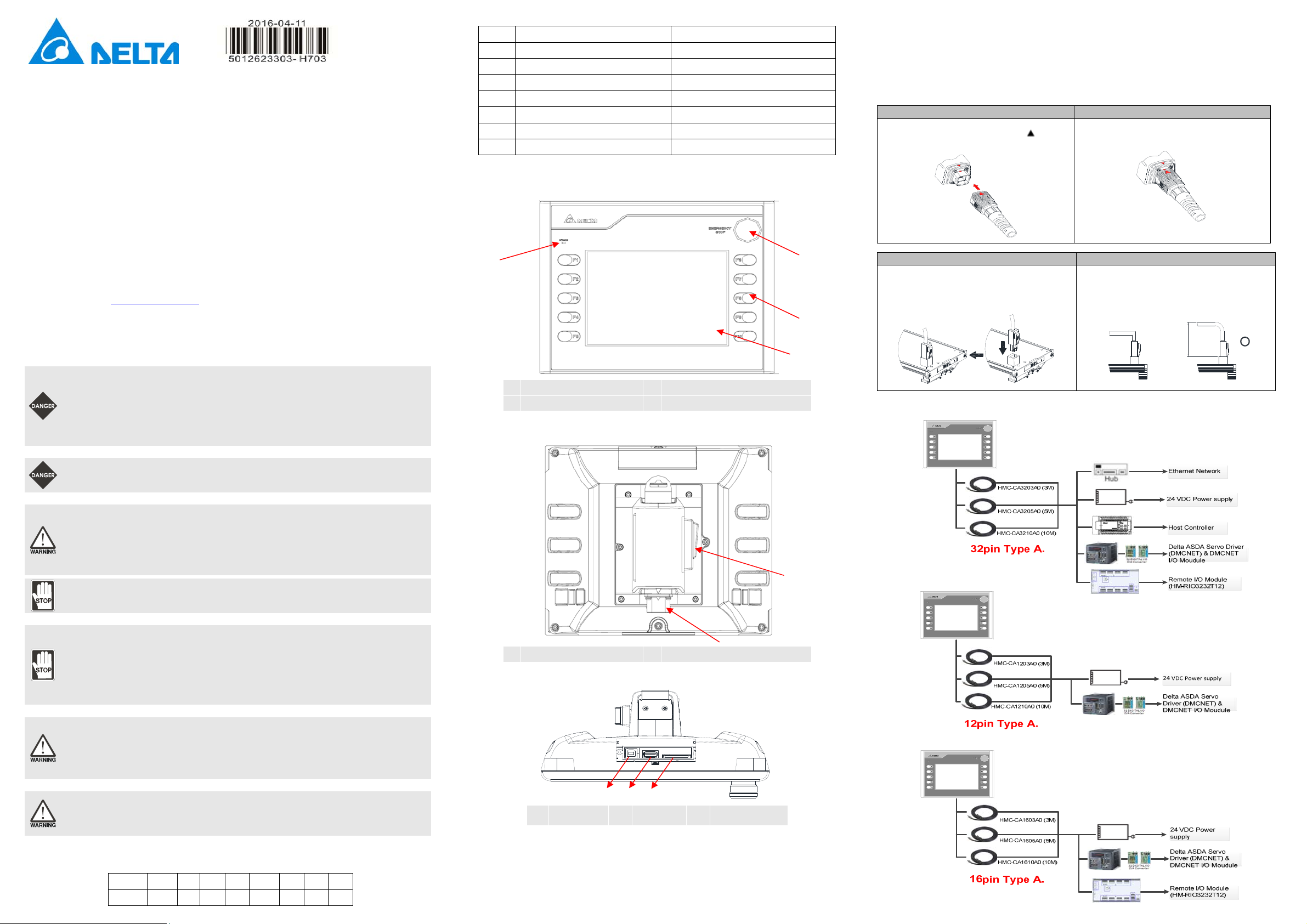
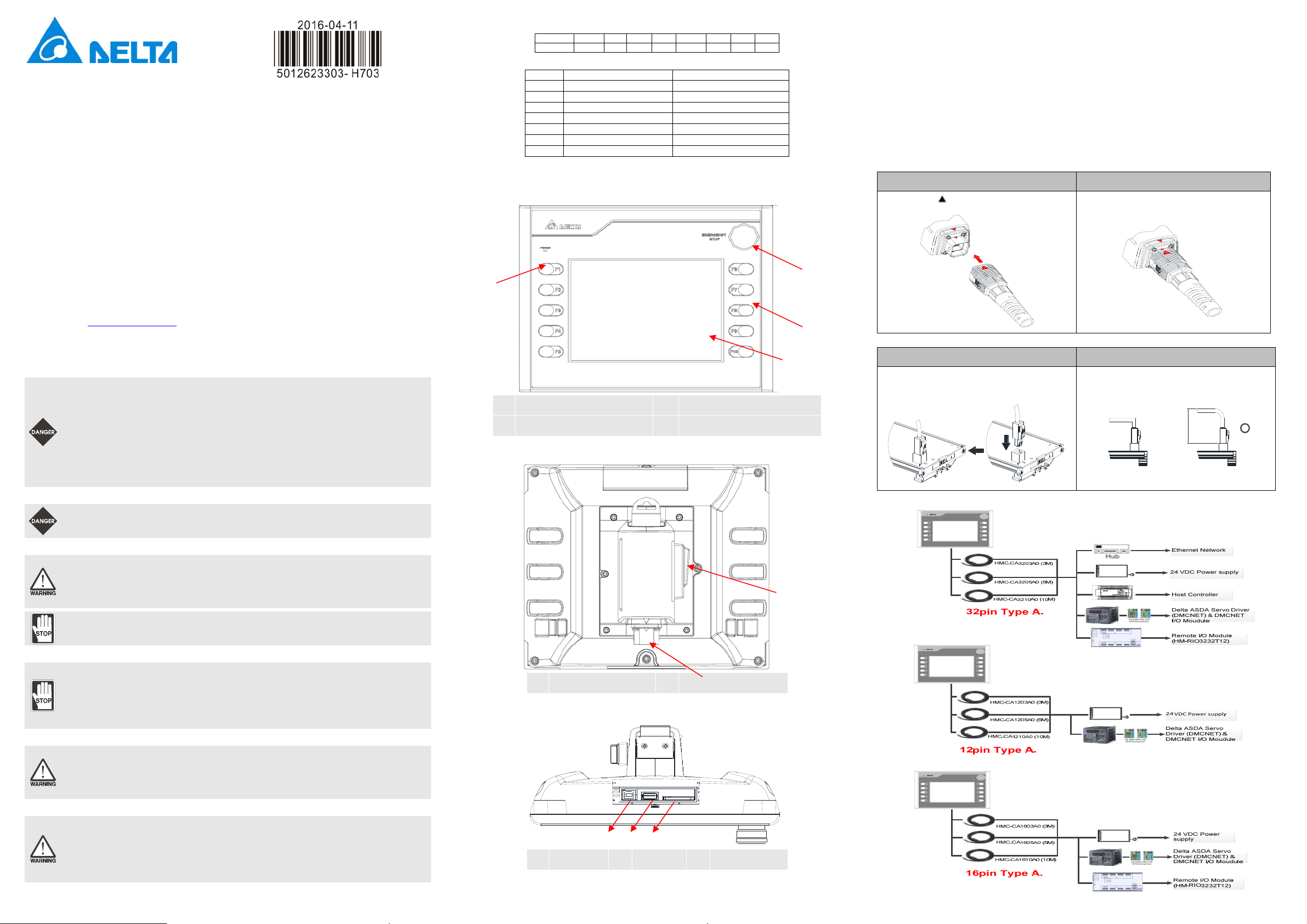
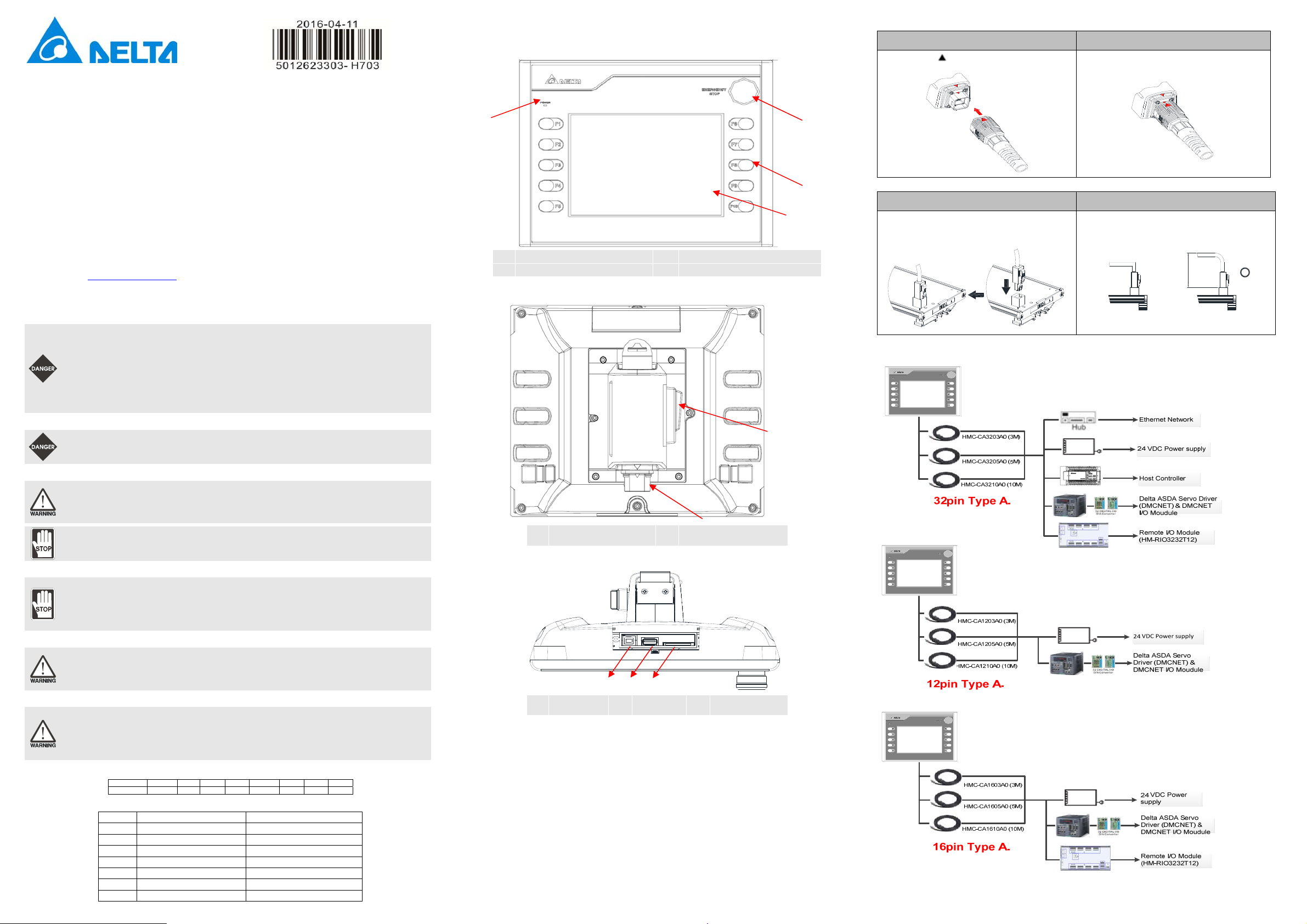
There are three wiring types for HMC07-N500H52: (a) 32 pin Type A; (b) 12 pin Type A; (c) 16 pin Type A
(a) 32 pin Type A: HMC-CA3203A0 (3M), HMC-CA3205A0 (5M), HMC-CA3210A0 (10M)
Color Name Explanation
White / Orange EMG_C Emergency stop switch b-contact
White / Orange EMG_C Emergency stop switch b-contact
White / Green EMG_O Emergency stop switch a-contact
White / Green EMG_O Emergency stop switch a-contact
Red Power System power 24V+
Black PGND System power grounding
White EGND Earth grounding
Yellow 422_TX+ RS422: TX+, RS232: TX, RS485: T+/R+
White / Yellow 422_TX- RS422: TX-, RS485: T-/R-
Black / White CGND Communication grounding
Black / White CGND Communication grounding
Black / White CGND Communication grounding
White / Blue ENA_O 3-position operation switch a-contact
White / Blue ENA_O 3-position operation switch a-contact
Purple 422_RX+ RS422: R+, RS232:RX
White / Purple 422_RX- RS422: R-
Black / Orange INT1 External interrupt 1 input (Reserved)
Black / Green INT0 External interrupt 0 input (Reserved)
Red / Black I_GND External interrupt grounding (Reserved)
White / Red I_PW External interrupt power 24V+ (Reserved)
RJ45 Blue DMC DMCNET connection
RJ45 Black ETH Ethernet connection
RJ45 Green RIO Remote I/O connection
(b) 12 pin Type A: HMC-CA1203A0(3M), HMC-CA1205A0 (5M), HMC-CA1210A0 (10M)
Color Name Explanation
White / Orange EMG_C Emergency stop switch b-contact
White / Orange EMG_C Emergency stop switch b-contact
White / Green EMG_O Emergency stop switch a-contact
White / Green EMG_O Emergency stop switch a-contact
Red Power System power 24V+
Black PGND System power grounding
White EGND Earth grounding
Black / White CGND Communication grounding
RJ45 Blue DMC DMCNET connection
(c) 16 pin Type A: HMC-CA1603A0 (3M), HMC-CA1605A0 (5M), HMC-CA1610A0 (10M)
Color Name Explanation
White / Orange EMG_C Emergency stop switch b-contact
White / Orange EMG_C Emergency stop switch b-contact
White / Green EMG_O Emergency stop switch a-contact
White / Green EMG_O Emergency stop switch a-contact
Red Power System power 24V+
Black PGND System power grounding
White EGND Earth grounding
Black / White CGND Communication grounding
RJ45 Blue DMC DMCNET connection
RJ45 Green RIO Remote I/O connection
(8) Basic Inspection
Item Content
General Inspection
Periodically inspect the screws of the connection between the HMI and device.
Tighten screws as necessary as they may loosen due to vibration and varying
temperatures.
Ensure that oil, water, metallic particles or any foreign objects do not fall inside
the HMI, control panel or ventilation slots and holes. As these will cause damage.
Ensure the correct installation and the control panel. It should be free from
airborne dust, harmful gases or liquids.
Inspection before
operation
(power is not applied)
Ensure that all wiring terminals are correctly insulated.
Ensure that all wiring is correct or damage and or malfunction may result.
Visually check to ensure that there are not any unused screws, metal strips, any
conductive or inflammable materials inside HMI.
Ensure to lower electromagnetic interference when devices are influenced by it.
Ensure that the external applied voltage to HMI is correct and matched to the
controller.
Inspection before
operation
(power is applied)
Check if power LED lights.
Check if the communication among devices is normal.
Please contact our local distributors or Delta sales representative if there are any
abnormal conditions.
(9) Specifications
MODEL HMC07-N500H52 / HMC07-N510H52 / HMC07-N511H52
LCD MODULE
Display Type 7-inch TFT LCD(65536 colors)
Resolution 800 x 600 pixels
Backlight LED Back Light(less than 20,000 hours half-life at 25oC) (Note 1)
Display Size 141 x 105.75mm
Operation System Delta Real Time OS
MCU HMI 32-bit RISC Micro-controller
Controller 32-bit DSP
NOR Flash ROM Flash ROM 128 MB(OS System: 30MB / Backup: 16MB / User Application:
82MB)
SDRAM 64Mbytes
Backup Memory (Bytes) 16Mbytes
Sound
Effect
Output
Buzzer Multi-Tone Frequency(2K ~ 4K Hz)/85dB
AUX N/A
Ethernet Interface IEEE 802.3, IEEE 802.3u
10/100 Mbps auto-sensing((has built-in isolated power circuit (Note 3))
Memory Card SD Card (supports SDHC)
USB 1 USB Host (Note 2) Ver 1.1 / 1 USB Slave Ver 2.0
Serial
COM
Port
COM1 RS-232/RS-422/RS-485
(has built-in isolated power circuit (Note 3))
COM2 N/A
COM3 N/A
Remote I/O Specialized 10M bps RS-422
Motion Control Bus DMCNET
Key /
Switch
Function Key 10 function keys
Emergency Stop
Switch
Push-lock switch 2 contacts
a-contact (normally open): 1 contact
b-contact (normally closed): 1 contact
Rated voltage: DC30V
Maximum rated current: 500mA
Minimum allowable load: DC5V, 1mA
3-Position Operation
Switch
Output switch 1 contact
a-contact (normally open): 1 contact
Rated voltage: DC30V
Maximum rated current: 500mA
Minimum allowable load: DC3V, 1mA
Perpetual Calendar Built-in
Cooling Method Natural air circulation
Safety Approval CE/UL (Note 4) /KCC (Note 4)
Operation Voltage (Note5) DC +24V(-10% ~ +15%)
(has built-in isolated power circuit (Note 3))
Voltage Endurance AC500V for 1 minute (between charging (DC24V terminal)
and FG terminals)
Power Consumption (Note 5) 8W
Backup Battery 3V lithium battery CR2032 x 1
Backup Battery Life It depends on the temperature used and the conditions of usage,
about 3 years or more at 25oC.
MODEL HMC07-N500H52 / HMC07-N510H52 / HMC07-N511H52
Operation Temperature 0oC ~ 50oC
Storage Temperature -20oC ~ +60oC
Ambient Humidity 10% ~ 90% RH [0 ~ 40oC], 10% ~ 55% RH [41 ~ 50oC]
Pollution Degree 2
Vibration
IEC 61131-2 compliant
5Hz≦f<8.3Hz = Continuous: 3.5mm,
≦≦8.3Hz f 150Hz = Continuous: 1.0g
Shock IEC 60068-2-27 compliant 15g peak for 11 ms duration
X, Y, Z directions for 6 times
Dimensions
(W) x (H) x (D) mm
238 x 199 x 129
(Emergency stop switch and projection are included.)
Panel Cutout
(W) x (H) mm 219.4 X 166.5
Weight Approx.1500g
NOTE
1) The half-life of backlight is defined as original luminance being reduced by 50% when the maximum driving current
is supplied to HMI. The life of LED backlight shown here is an estimated value under 25oC normal temperature and
humidity conditions.
2) USB Host port can provide up to 5V/ 500mA of power.
3) The withstand voltage of the isolated power circuit is 1500V peak for 1 minute.
4) Some models are in the process of application to UL and KCC certification. For more information, please consult
our distributors.
5) The value of the power consumption indicates the electrical power consumed by HMI only without connecting to
any peripheral devices. In order to ensure the normal operation, it is recommended to use a power supply which
the capacity is 1.5 ~2 times the value of the power consumption.
6) Users can download the DOPSoft, the program editor of Delta HMI product and the user manual via the following
link: http://www.delta.com.tw/ia.
7) The content of this instruction sheet may be revised without prior notice. Please consult our distributors or
download the most updated version at http://www.delta.com.tw/ia .