ALLEN LEIGH PTZ-IR COWCAM User manual
Cow Cam Installation Instructions
20
Make your analog system
smart phone compatible!!
Watch from the comforts of home or take
your work with you and monitor your system
from your smart phone.
With the DVR & data radio kit you
can have it all.
This kits includes the data radio, 1 receiver,
IP support and DVR
$550 for 2.4ghz system
$600 for 5.8ghz system
Cow Cam Installation Instructions 1
PTZ-IR

Cow Cam Installation Instructions
2
Thank you for purchasing your PTZ-IR Livestock
Monitoring System (Cow Cam) from us. You will
get many years of use from your new wireless
video system, it comes with a one-year warranty
on parts and labor, and we guarantee it to work
when installed according to our assessment.
The system consists of two physical parts, a trans-
mitting point, and a receiving point.
***You will want to assemble the system in
your house first before you install it perma-
nently on your barn or shed, this is to ensure
that you have your TV or VCR setup properly,
and you understand the proper connections.
***
On the end where the camera will be located (the
barn) is also where the transmitter box and power
supply box will be mounted (on the outside of the
building facing the location where the receiver
will be located) The transmitter and camera will
be connected together with the camera cable. The
power box will also be connected to the camera.
The receiver will be located at the viewing loca-
tion (your house) and connected to your TV with
the RCA cables. The camera controller will also
be located at the house.
The power supply box will come with a cord that
gets plugged into the transmitter at the barn, and a
cord which provides power for the camera.
Cow Cam Installation Instructions 19
If you purchased the optional direc-
tional High Gain Antenna to get better
distance, you will want to use the same
guide lines as above. You will need to
remove the rubber tube antenna and re-
place it with the coax from the High
Gain Antenna. Please be aware that the
base of the 6DB antenna is Magnetic so
DO NOT mount it on top of or next to
the TV or Tapes, as it will cause discol-
oration and possible damage to the TV
and tapes. Make sure that the antenna is
pointing towards the transmitter or re-
ceiver (if it is on the receiver then point
it to the transmitter and visa versa).

Cow Cam Installation Instructions
18
There are a few things that will in-
terfere with your signal on your Wire-
less Livestock System one for sure is
the microwave oven when it is in use,
and we have also experienced problems
with any other 2.4 GHz devices like
cordless telephones, wireless routers,
wireless internet, Bluetooth and some
gaming systems.
To determine which one it is you
may need to unplug each one by one to
verify which is causing the interference
If you have any problems please refer to our website for a
step by step troubleshooting chart www.cowcam.ca this will
take you directly to the support page:
If you have tried these steps and still unable to fix the prob-
lem please give us a call to speak to our helpdesk;
Office 204-728-8878 or toll free 1-866-289-8164
Cow Cam Installation Instructions 3
1. 1 - Transmitter Box (Cream Colored/ Grey Box)
2. 1 - Power Supply box (Grey Box)
3. 2 -30 ft. Power Cables (red with black & Orange ends)
4. 1 - 6 pin 30 ft. PTZ Camera Cable
5. 1 - RCA Cable (not shown in picture)
6. 1 - Home Receiver
7. 1 - PTZ-IR Cam Manual
8. 1 - PTZ Camera (Large/ Mini)
9. 1 - Camera Controller
10. PTZ Installation DVD (not show in picture)

Cow Cam Installation Instructions
4
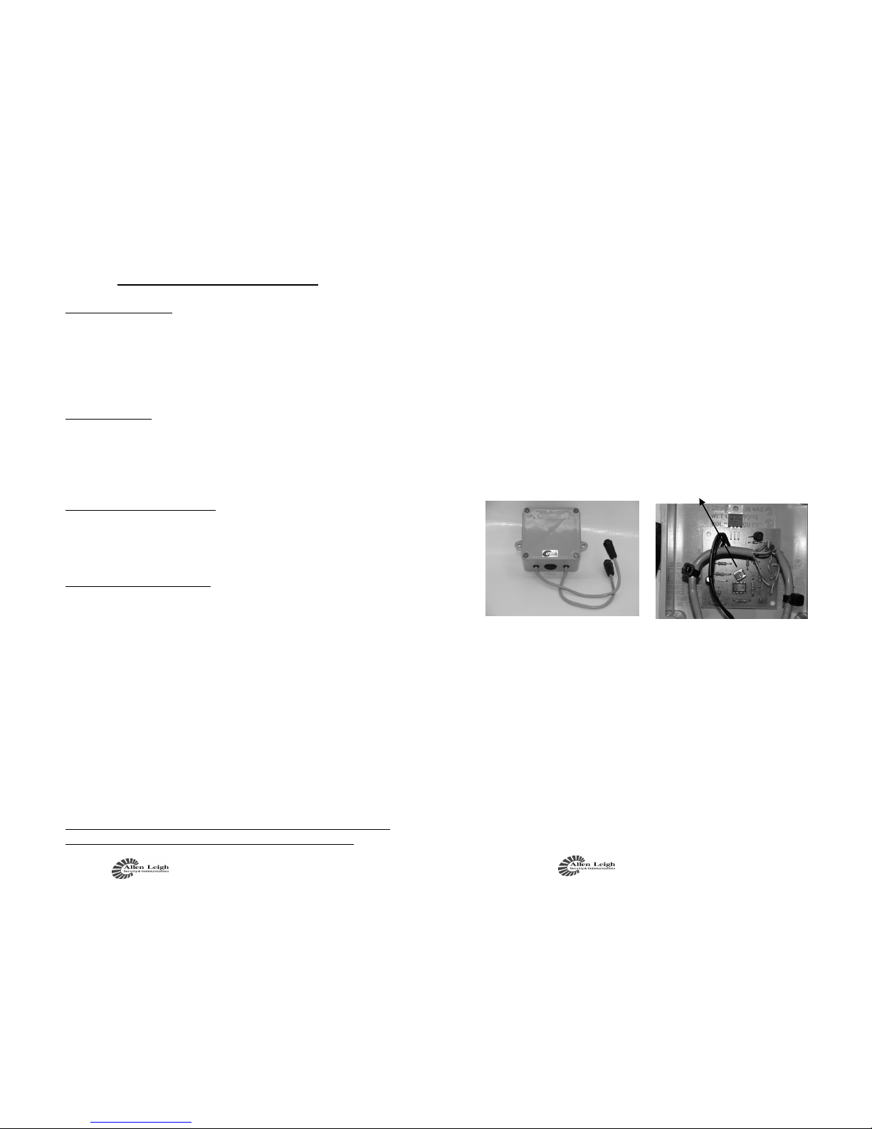
Transmitter Information
If you unscrew the 4 Philips screws on the front of the
transmitter you will be able to take the cover off. Please do not
overt tight them as they will break
Inside of the transmitter box you will find a LCD display
this will tell you what channel this particular transmitter is on, it
can be switched to one of seven frequencies. You can change the
channels by using a small point pen or pin. If you push the chan-
nel selector once, it will go to channel two, push it again and it will
go to channel 3, and so forth.
Be sure not to have more then one transmitter set on the
same channel, i.e. channel one (you won’t damage anything but
the video picture at the house will look very scrambled). Ensure
that the channel you have the transmitter set on matches the chan-
nel on the receiver at the house.
Please note that these instructions are for the 5.8ghz system
if you have the 2.4 ghz system please refer to pages 16 & 17.
There is no on/off switch for the transmitter or camera; the
only way to turn it off is to unplug the unit.
Cow Cam Installation Instructions 17
There is no on/off switch for the transmitter or camera;
the only way to turn it off is to unplug the unit.
We strongly recommend that you unplug the unit after
your calving season is complete, damage may occur during
thunderstorms and extremely high winds due to power lines
clashing. You will know that the unit is powered on when the
channel indicator is lit inside the transmitter box.
There is a mounting bracket that is sent with the unit so you
can mount it to a post or pole outside, or you can use the holes
to drill it to an outside wall. Install it so it fits tightly to the
whatever you mount it to. Drill a hole large enough for the
Switch-Craft connector to go through to the barn wall or
wherever you want to mount your camera. Attach the male
camera cable end to the female end on the transmitter box.
Caution: ensure the cable does not get cut by any sharp edges
from the hole you cut. Also be sure to aim the transmitter so
that it points towards where the receiver is located. The trans-
mitter should be mounted in the vertical position with the
mounting hardware on the bottom with the transmitter sticker
facing the receiver location.
Channel
Selector
Switch
Channel Light Indicator
(Channel 1 is far right)

Cow Cam Installation Instructions
16
Switch-Craft
Connector,
connect this
to the camera
cable
Transmitter
Box
Data Radio
Receiver
Power
Cable
Transmitter Information
If you unscrew the 2 Phillips screws on the bottom of the
transmitter you will be able to take the cover off.
Inside of the transmitter box you will find a series of lights
(4) on a small board, these tell you what channel this particular
transmitter is on, it can be switched to one of four frequencies. The
switch is a small round rod on a small square switch usually la-
beled as SW1 on the upper left side of the switch. If you push the
channel selector (Black plastic rod) once, it will go to channel two,
push it again and it will go to ch 3, and so forth.
Be sure not to have more then one transmitter set on the
same channel, i.e. channel one (you won’t damage anything but
the video picture at the house will look very scrambled). If your
unit appears to have more than 4 channels then simply unplug the
transmitter and hold down the channel button while you plug it
back in and release within 5 seconds. Ensure that the channel you
have the transmitter set on matches the channel on the receiver at
the house.
Cow Cam Installation Instructions 5
We strongly recommend that you unplug the unit after
your calving season is complete, damage may occur during
thunderstorms and extremely high winds due to power lines
clashing. You will know that the unit is powered on when the
channel indicator is lit inside the transmitter box.
There is a mounting bracket that is sent with the unit so you
can mount it to a post or pole outside, or you can use the holes
to drill it to an outside wall. Install it so it fits tightly to the
whatever you mount it to. Drill a hole large enough for the
Switch-Craft connector to go through to the barn wall or
wherever you want to mount your camera. Attach the male
camera cable end to the female end on the transmitter box.
Caution: ensure the cable does not get cut by any sharp edges

Cow Cam Installation Instructions
6
Basic Setup Instructions:
First, you will want to make sure that you have all the equip-
ment. Once you have verified that you have it all, we will begin the in
home assembly , make sure you know how to set it up in the house
before you try to install it outside.
Indoor Equipment
Begin by plugging the power supply for the receiver into the
back of the receiver (IN port). Plug the Yellow RCA cable into (video)
the back of the receiver and the other end will plug into your T.V,
VCR, or DVR (into the yellow video jack). (The standard channel select setting for the
receiver is #1). You only need to connect the audio RCA cables (white/
red) if you purchased the optional Audio modification box.
Screw the mini bud antennae to the back of the PTZ controller, finger
tight. Connect the power supply to the PTZ camera controller. This
will be the only connection to the controller that is required—the unit
operates wirelessly.
Please note that the controller is not connected to video it controls
camera movement only.
The signal to operate the movement of the camera will be sent wire-
lessly via the antennae on the PTZ controller.
Cow Cam Installation Instructions 15
If you have any problems please refer
to our website for a step by step trou-
bleshooting chart www.cowcam.ca this
will take you directly to the support
page:
If you have tried these steps and still
unable to fix the problem please give us
a call to speak to our helpdesk;
Office 204-728-8878 or toll free 1-866-
289-8164
Thank You and Enjoy!
Allen Leigh Security &
Communications Team
**Please refer to the next pages if you have pur-
chased a 2.4ghz system.

Cow Cam Installation Instructions
14
If you see the above screen information displayed you have made the
correct option choices. The numbers may look a bit confusing, hope-
fully the following explanation helps.
Where you see 01. 001 005
1. 01. represents the start of the Tour (there are 12 tour locations)
2. 001 represents the camera pre-set location
3. 005 is the length of time to stay on that pre-set point in seconds
Use the joystick to move the arrow to the number that you want to
change, when you are on the number you want to change use the
“NEAR” and “FAR” buttons to increase or decrease the number.
You can set the tour to start with any one of your pre-set locations,
and have it stay on for the length of time you want in seconds. You
can have up to 12 tour locations set if you like.
Once you have the tour set to your liking, press the “OPEN” button
(also known as Iris +) to save and then Press “CLOSE” button to exit.
To View your tour on the Controller keyboard press “142”
“CALL”
Cow Cam Installation Instructions 7
Outdoor Equipment
Now that you have the receiver and controller set up, we will
now set up the outdoor equipment. Starting with the camera, plug
the camera cable into the 6-pin male connecter end on the camera.
The other end of the camera cable will be connected to the bottom
of the transmitter where there is a 6-pin female connector that it will
plug into.
Next take the power cable from the power supply box with
orange end and plug it into the matching plug on the camera. An
optional extension cable may be supplied. The cable with the black
end from the power supply box will get plugged into the matching
plug on the transmitter.
Both of the power cables will get plugged into the grey power
supply box. Making sure that the color coordinated cables are
matched Plug in the power supply box to a 110V outlet and the
camera will begin is startup routine. During which time it will dis-
play on the TV screen its information such as its address, baud rate,
and protocol.
Once you plug in the controller, make sure that you set the
PTZ controller’s address to match that of the camera. Normally the
camera and controller addresses will be 01 (001), but that is not al-
ways so.
Make sure that the controller and camera are on the same ad-
dress, take note of what the address of the camera is from the TV s
when it does its startup routine, and then enter in that address num-
ber on the keypad of the PTZ Controller followed by the CAM but-
ton. (Eg Dome ID: 001, on the keypad of the controller press: 01 on the PTZ controller
then CAM button. That will set the address on the keypad to 01 and you will be able to
control the camera with address 01.)
Cow Cam Installation Instructions
8
Outdoor Assembly:
Step 1.
Connect everything at the house first to make sure everything
is working fine. If not please refer to our website for step-by-
step troubleshooting (www.cowcam.ca)
Once you have tested everything inside, you can leave the
receiver and joystick controller assembled and powered up.
Everything else is going outside.
Step 2.
Mount the camera at the ideal position to a firm and solid
surface.
Step 3.
Mount the PTZ transmitter at the ideal location to get the best
signal back to the house. Make sure it is facing towards the house.
with the connections on the bottom.
Step 4.
Mount power box and plug it into 110v AC and run the power
cables to the PTZ camera and transmitter.
Step 5.
Run the camera cable (with the 6 pins on the connectors)
between the transmitter box and the camera. The male end of
the cable connects to the transmitter and the female end
connects to the camera.
Step 6.
Go back to the house and make sure that the camera number is
still displayed on the joystick screen. You should now be able
to control the camera. If not, reposition the PTZ controller to
get it up a bit higher, to clear any obstacles.
Make note of the address number on the screen when it does
its startup. This is the number that should be displayed on the
joystick controller. If it does not, enter the 2 digit number and
press “CAM” on the joystick controller.
Cow Cam Installation Instructions 13
Creating Preset Location Points
1. Position your camera on the point of interest that you want
to view, you can zoom in/out on the object location.
2. Once you have your location determined, on the Controller
keypad press “PRESET” then the location number you
want to create (such as 1, 2,3, etc) and “PRESET” button
again
3. Continue the above step for each separate location you want
to create (giving it its own number preset 1-90)
4. There is room to create up to 90 locations ranging from #1
to #90
5. To check your preset locations press the preset number on
the keypad (for that location) and then CALL button. An
example sequence would be “3” “CALL” which would
move the camera to the preset location you made called #3.
To Create a Tour of your Preset Locations
When you have all of your preset location made you can
use this next step to view them automatically in whatever order
you want in a continuous order.
1. On the Keyboard PTZ Controller, press “95” “CALL” to
get into the PTZ cameras on-screen display
2. When you see the on-screen display on your TV, use the
joystick (push down) to scroll down to #3 Auto-Run, then
press the “NEAR” button to enter (NEAR button is on the
left 3 from the top)
3. On the next screen use the joystick to go down to #3
TOUR, and press the “NEAR” button to enter
4. On the next screen use the joystick to go down to #2 SET-
UP, and press the “NEAR” button to enter
5. You will now be in the setup screen to setup up the Tours.
See next page for a snapshot of what the screen will look
like if you have done the above steps correctly!
Cow Cam Installation Instructions
12
Zoom in / Zoom out
1. Turn the joystick controller knob counter clock-
wise to zoom out and clockwise to zoom in
2. Or you can use the “TELE” button (top left side
of controller) to zoom in, and “WIDE” button to
zoom out
Moving Camera
To move the camera you push the joystick left to move
to left and right to move the camera to the right.
The harder you push the joystick, the faster the camera
moves, a slight push moves the camera slowly.
MENU button on Controller
The “MENU” button on the controller, is for advanced
controller option such as Keypad light, baud rate, and tones.
Only use this function if you are an advanced user!
How to make an Auto Scan
1. Move your camera to the furthest left position that you
want the camera to scan to
2. On controller keyboard press “130” and then the
“CALL” button (your left limiter is now set)
3. Move the joystick to position the camera to the furthest
right location you want to scan to
4. On controller keyboard press “131” and then the
“CALL” button (your right limiter is now set)
5. To view the Auto Scan that you set press either
“132” , “133” or “134” and then “CALL” button to
start scan
132 = Low Speed scan
133 = Medium Speed Scan
134 = High Speed Scan
To Stop the Auto Scan, just move the joystick, to restart use
the appropriate speed number and CALL button again
Programming / Camera Operations
Cow Cam Installation Instructions 9
If the Audio Modification Box option was purchased, you
will have two cable ends, they are setup so that the camera end will
fit into one side and the camera cable into the other the connectors,
the connectors on the audio box are opposites. The audio modifica-
tion box is designed to be mounted onto the wall it has mounting
holes for it. You can mount the audio mod either right before the
camera or the transmitter box which ever works best for you. On the
inside of the Audio device you will see a small orange pot, this is
how you would adjust your audio sensitivity, turning to the right
increases sensitivity and to the left decreases the sensitivity.
Metal siding will not allow a strong signal into the home if the
receiver is placed behind it, so you will want to try to place the re-
ceiver near a window location. You may have to re-position the an-
tenna angle on the receiver in order to find the best signal with the
basic models you may find that you have to move the receiver up or
down, trial and error will get you the best signal.
Audio
Box
Audio Sensitivity Control

Cow Cam Installation Instructions
10
Picture Problems
If you do not get a picture right away, upon your complet-
ing your connection you may have to unplug and plug the trans-
mitter back in, this does a system reset, and usually rectifies the
problem if there is no picture from the system.
If you are within Manitoba please do not forget to send
one copy of your invoice back to us with your township, range
and signature for Cow Cam to be PST exempt!
If you have any problems please refer to our website for a step by
step troubleshooting chart www.cowcam.ca this will take you di-
rectly to the support page:
If you have tried these steps and still unable to fix the problem
please give us a call to speak to our helpdesk;
**Please note for the basic system it is
very important that the receiver be locat-
ed on the same side of the house as the
transmitter is located (you may try other
locations once you have acquired your
signal) preferably on the inside of the
outside wall so the two units can see one
another through only one wall with as lit-
tle obstruction as possible.
Cow Cam Installation Instructions 11
Trees, shrubs and hay bales do not seem to hin-
der the picture quality too much during the winter,
trees do effect the signal once the leaves come out. You
may find that you may have to adjust the antenna or the
receiver unit by lifting it up for better reception.
If you have buildings or machinery in the way, it
will possibly lower your picture quality, it also depends
on what the buildings are made of, metal or large ma-
chinery block the signal. It is best not to have anything
in the way of the signal path, we understand that you
cannot move buildings so try to position the transmitter
higher up above the roofline or higher than the objects
in the way.
If you are placing the receiver in front of a win-
dow and you are not getting a good picture it could be
due to the high energy efficiency of the window. New
windows contain Argon gas or a coating that seems to
block the signal, just move the receiver over from the
window and you will more than likely get a signal.
We do have optional antennae's that are available
as well as outdoor receivers.
Table of contents


