simalube 250 User manual

DE
Anwenderhinweise
Technische Information
Originalsprache – Vor Gebrauch lesen
EN
User Manual
Technical Information
Read before use
FR
Mode d’emploi
Informations techniques
A lire avant utilisation
ES
Manual del usuario
Información técnica
Leer antes de usar
IT
Istruzioni per l’uso
Informazioni tecniche
Leggere le istruzioni prima dell‘uso
Get the simatec app «world of maintenance»

Get the simatec app «world of maintenance»
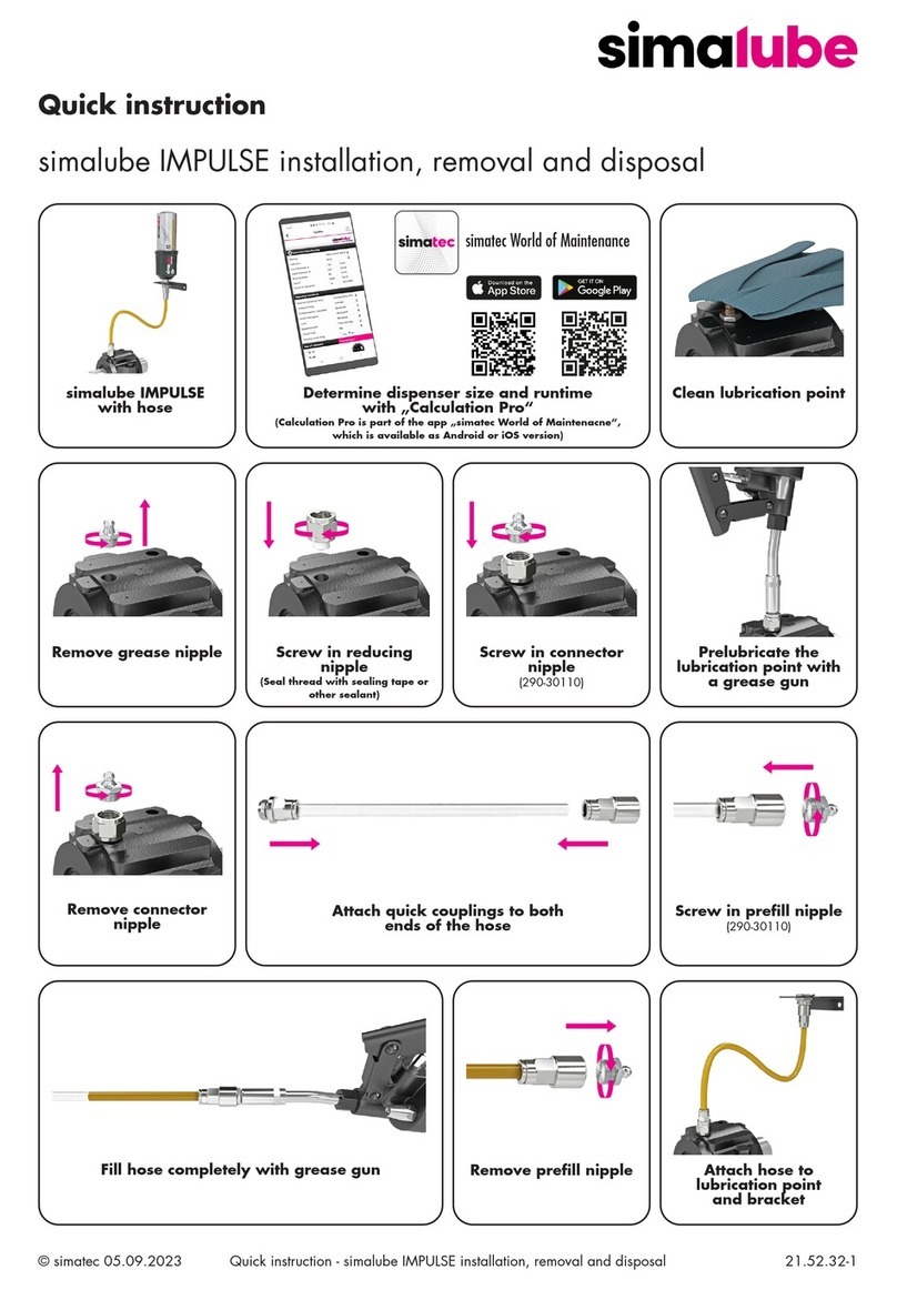
With the «simatec world of maintenance» app, simatec ag has created a platform for
easier and more efcient management of lubrication work. The app offers the user
the possibility to record lubrication points, to set the necessary parameters for the lu-
brication and to control or monitor all activities around the lubrication. The simalube
IMPULSE connect, equipped with Bluetooth®, can be congured directly via the app.
The current operating status can be viewed from a distance of up to 20m via the app.
The «simatec world of maintenance» app can be downloaded from the Apple Store and
the Google Play Store and installed on the smartphone.
DE
EN
FR
ES
IT
Deutsch Original 3–11
English Translation 12–20
Français Traduction 21–29
Espanõl Traducción 30–38
Italiano Traduzione 39–47

3
DE
Sicherheitshinweis
Wird der Spender ohne zu öffnen in Betrieb genommen, oder sind die Fettkanäle ver-
stopft, kann sich der Druck im Spender bis zu ca. 5 bar aufbauen. Bei einem Überdruck
von ca. 6 bar platzt der Spender an der Sollbruchstelle zwischen Gehäuse und Trichter.
Der Druck hinter dem Kolben entspannt sich, aus der Sollbruchstelle kann Fett oder Öl
austreten.
Warnung: Bei Anwendungen in einer Umgebung mit explosionsfähiger
Atmosphäre besteht das Risiko elektrostatischer Entladungen oder von
Gleitstielbüschelentladungen an der Oberäche des Schmierstoffspenders.
Zur Minimierung des Risikos sind geeignete Vorkehrungen zu treffen.
Den Schmierstoffspender nur mit einem feuchten Lappen reinigen, um
eine elektrostatische Auadung bei der Reinigung zu vermeiden. Den
Schmierstoffspender keinem Luftstrom aussetzen, der zur elektrostatischen
Auadung des Schmierstoffspenders führen kann.
Die einwandfreie Funktion des Schmierstoffspendesystems wird nur durch Verwendung
der empfohlenen Schmierstoffe des original simalube Zubehörprogramms und bei
Beachtung der Montage-, Betriebs- und Wartungsvorschriften erreicht. Bei Nichtbeach-
tung dieser Vorschriften schliesst der Hersteller jegliche Haftung für Folgeschäden aus.
Wichtig: Vor Inbetriebnahme des simalube, Verlängerungen und Fettleitungen mit ent-
sprechendem simalube Fett (Kartuschen SL01…SL26) mittels Fettpresse durchschmieren
und Fettkanäle füllen. Nur Originalzubehör verwenden.
simalube wurde von folgenden Institutionen auf Sicherheit geprüft und zugelassen:
Typ 30, 60, 125 ml:
II 1 G Ex ia IIC T6 Ga
II 1 D Ex ia IIIC T200 80°C Da
I M1 Ex ia I Ma
Typ 250 ml:
II 1 G Ex ia IIC T4 Ga
II 1 D Ex ia IIIC T200 135°C Da
I M1 Ex ia I Ma
Antriebssystem: Wasserstoff-Gasentwicklungszelle (Trockenelement)
Einsatztemperatur: –20°C bis +55°C Umgebungstemperatur

4
Einbau und Inbetriebnahme
1) Schmierstoffauslass öffnen, indem der Ver-
schlussstopfen entfernt wird.
Bei ölbefüllten Spendern Stopfen nicht
entfernen! Vorstehenden Nippel mit Messer
abschneiden, bis ein kleiner schwarzer Punkt
sichtbar wird (Öffnung ist nun gewährleistet).
2) Um den simalube Schmierstoffspender zu star-
ten, wird die Spendezeit (in Monaten stufen-
los wählbar zwischen 1–12) am Antriebskopf
mittels Schraubenzieher oder einer Münze
eingestellt. Ist die Spendezeit eingestellt, ist
der Spender aktiviert. Gewünschte Spende-
menge aus den Tabellen, siehe Seite 6–7,
ableiten.
3) Startdatum mit wasserfestem Filzstift auf
Etikette eintragen.
4) Fettkanäle mittels Fettpresse durchschmieren.
simalube an Schmierstelle einschrauben.
Wenn erforderlich, Zubehörteile verwenden
(siehe https://simatec.com/de/simalube/
zubehoer-1). Sicherheitshinweis beachten.
5) Nach Ablauf der vorgewählten Laufzeit den
leeren Schmierstoffspender durch gleichen
Typ ersetzen oder nachfüllen. Vor erneuter
Inbetriebnahme Fettkanäle mittels Fettpresse
durchschmieren.
6) Der Antriebskopf reicht für eine Entleerung,
unabhängig von der eingestellten
Laufzeit.
DE

5
G 1/4“
Ø52mm (2.05in)
14
mm
(0.55in)
47 mm (1.9 in)
simalube 30
G 1/4“
Ø52mm (2.05in)
14
mm
(0.55in)
66 mm (2.4in)
simalube 60
G 1/4“
Ø52mm (2.05in)
14
mm
(0.55in)
104 mm (4.1in)
simalube 125
G 1/4“
Ø52mm (2.05in)
14
mm
(0.55in)
198 mm (7.8 in)
simalube 250
DE
Produktspezikation
Produkt Automatischer Einzelpunkt-Langzeitspender für Fette und Öle.
Bestimmungsgemässe
Verwendung
Die automatischen Schmierstoffspender simalube werden
an Maschinen und Anlagen zur Schmierung von Bauteilen
jeglicher Art verwendet. Der Anbau erfolgt direkt oder über
speziell dazu ausgelegte Zubehörteile.
Antriebssystem Wasserstoff-Gasentwicklungszelle (Trockenelement)
Betriebsdruck max. 5 bar
Einstellung stufenlos 1–12 Monate (für Standardbedingungen)
Spendemenge siehe Tabellen Seite 6–7
Einsatztemperatur –20°C bis +55°C Umgebungstemperatur
(Hinweis: Fettkonsistenz ändert sich mit der Temperatur)
Risiken/Gefahren Trotz sorgfältigster Konstruktion kann es zu Hautkontakt mit
Schmierstoff kommen. Dieser ist sofort mittels Wasser/Reini-
gungsmittel zu entfernen.
Schutzart IP68 (staub- und wasserdicht)
Verwendungszeit Innerhalb von 2 Jahren nach Produktionsdatum aktivieren
Lagerungstemperatur empfohlen bei 20°C ±5°C
30ml 60ml 125ml 250ml
Gewicht voll ~82g ~115g ~190g ~335g
Gewicht leer ~55g ~60g ~75g ~111g

6
Temperatur/Spendemengen
Die Spendemenge kann bei Bedarf in Abhängigkeit von der Umgebungstemperatur
stufenlos angepasst werden (vgl. Tabelle).
Beispiel: Die gewünschte Laufzeit für einen simalube 125 ml beträgt 180 Tage.
Umgebungstemperatur: 20°C Umgebungstemperatur: 55°C
Einstellung: 6 Einstellung: 7
DE
simalube 30
Laufzeit (Tage) 30 90 180 270 360
ml/Tag 1,00 0,33 0,17 0,11 0,08
Temperatur Einstellung Einstellung Einstellung Einstellung Einstellung
–20°C + 2 3.5 5.5 7.5
4°C + 2.5 5 7.5 10.5
20°C 1 3 6 9 12
40°C 1 3 6.5 9.5 –
55°C 1 3.5 7 10.5 –
+ Grösseren Spender mit höherer Laufzeit verwenden
– Kleinstmögliche Spendemenge erreicht
simalube 60
Laufzeit (Tage) 30 90 180 270 360
ml/Tag 2,00 0,67 0,33 0,22 0,17
Temperatur Einstellung Einstellung Einstellung Einstellung Einstellung
–20°C + 2 4 6.5 8
4°C + 2.5 5.5 9 10.5
20°C 1 3 6 9 12
40°C 1 3 6.5 9.5 –
55°C 1 3.5 7 10.5 –
+ Grösseren Spender mit höherer Laufzeit verwenden
– Kleineren Spender mit niedrigerer Laufzeit verwenden

7
DE
simalube 125
Laufzeit (Tage) 30 90 180 270 360
ml/Tag 4,17 1,39 0,69 0,46 0,35
Temperatur Einstellung Einstellung Einstellung Einstellung Einstellung
–20°C + 2 4 6.5 8.5
4°C + 2.5 5.5 8 10.5
20°C 1 3 6 9 12
40°C 13 6.5 9.5 –
55°C 1 3.5 7 10 –
+ Grösseren Spender mit höherer Laufzeit verwenden
– Kleineren Spender mit niedrigerer Laufzeit verwenden
simalube 250
Laufzeit (Tage) 30 90 180 270 360
ml/Tag 8,33 2,78 1,39 0,93 0,69
Temperatur Einstellung Einstellung Einstellung Einstellung Einstellung
–20°C ++ 2 4.5 7.5 9.5
4°C ++ 2.5 5.5 8 10.5
20°C 1 3 6 9 12
40°C 1 3 6 9 –
55°C 1 3.5 6.5 9.5 –
++ 2-fach-Adapter verwenden
– Kleineren Spender mit niedrigerer Laufzeit verwenden
Die Werte beziehen sich auf Laborbedingungen, SL01 bei freiem Auslauf. Vor allem bei
tiefen Temperaturen können die Werte zwischen den verschiedenen Fetten abweichen.
Die Spender müssen nach Ablauf der eingestellten Laufzeit ersetzt werden, auch wenn
sie nicht vollständig entleert sind.
Die gespendete Fettmenge/Tag wird beeinusst durch:
– den Widerstand/Gegendruck im Leitungssystem
– die Umgebungstemperatur
– die Viskosität des Schmierstoffes
Anlaufzeit:
Der Schmierstoffspender benötigt eine Anlaufzeit bis zum ersten Schmierstoffaustritt.
Die Anlaufzeit variiert entsprechend der gewählten Spendemenge, Spendergrösse
und Betriebstemperatur. Beispielsweise bei 20°C Umgebungstemperatur und einer
Spendedauereinstellung von 12 Monaten fördert der Spender innerhalb einer Woche
Schmierstoff. Bei tiefen Temperaturen (–20°C) oder kleinen Spendern (30 ml) verdoppelt
sich die Anlaufzeit.
Die Anlaufzeit kann reduziert werden, indem man den Schmierstoffspender für ein bis
zwei Tage mit einer Spendedauer von einem Monat und danach auf die gewünschte
Spendedauer einstellt.

8
DE
simatec App «world of maintenance»:
Hinweise:
Wichtig für das zuverlässige Funktionieren sind durchgängig gefüllte Fettkanäle. Es muss
sichergestellt werden, dass die Fettkanäle nicht verstopft sind. Deshalb müssen diese vor
jeder Inbetriebnahme der Spender mittels Fettpresse durchgeschmiert werden.
Die Laufzeit des simalubes kann nach Aktivierung geändert oder abgeschaltet werden.
Die Werte auf der Einstellscheibe beziehen sich auf die Laborbedingungen (siehe Tempe-
ratur/Spendemengen – Seite 6–7).
Abhängig von Einstellung und Temperatur kann es nach dem Starten einige Stunden,
bei Langzeiteinstellungen einige Tage bis zum ersten Schmierstoffaustritt dauern. Der
Anwender muss die Funktion des simalubes regelmässig kontrollieren.
Anschlussleitungen dürfen nicht länger als 0,5 m sein. Empfohlener Bohrungsdurchmes-
ser: 6–8 mm. Leitungswiderstände sind zu minimieren, Verengungen und eckige Winkel
sind nicht zulässig. Bei starken Vibrationen oder hohen Beschleunigungen Montagesup-
port (siehe https://simatec.com/de/simalube/zubehoer-1) verwenden. Bei längeren
Schmierleitungen oder hohem Gegendruck den Druckverstärker simalube IMPULSE
connect (Art. 230-10100) verwenden.
Der simalube darf nur für die Versorgung von einer Schmierstelle verwendet werden. Es
dürfen keine Verzweigungen gemacht werden. Ist der Spender installiert und aktiviert,
darf er nicht abgeschraubt und auf eine andere Schmierstelle montiert werden.
Recycling-Hinweis
1) Antriebskopf (SW 27) herausschrauben und unzerlegt ins
Batterie-Recycling geben. Hinweis: Nie in der Nähe von offenem
Feuer herausschrauben.
2) Leeres Gehäuse ins Kunststoff-Recycling geben. Noch vorhan-
dene Fettreste sind separat zu entsorgen. Lokale Vorschriften
beachten.

9
DE
Erst- und Wiederbefüllung (bei kleinen Stückzahlen)
Erstbefüllung mit Fett
1a) Kolben durch leichtes Anblasen mit Druckluft
oder mit Hilfe eines Stabes (Durchmesser
7 mm) ganz nach vorne, Richtung Trichter
bzw. Auslassöffnung schieben.
2a) Nachfüllnippel (Art. 290-30120) aufschrau-
ben und Fettpresse anschliessen, oder
Anschlussnippel (Art. 290-30130 bzw.
290-30140) auf Fettpresse aufschrauben.
Der Spender wird dabei während des
Füllvorgangs gegen den Adapter gedrückt.
Dadurch entfällt das wiederholte Auf-
schrauben des Nachfüllnippels. Fett in den
Spender pressen. Auf blasenfreie Füllung
achten. Füllvorgang so lange fortsetzen, bis
der Kolben ganz zurückgeschoben ist. Nicht
überfüllen! Vorsicht: Handhebelpres-
sen können mehr als 100bar Druck
aufbauen. Dies kann ausreichen, um
den Spender zu zerstören!
3a) Wenn der Spender zwischengelagert wer-
den soll, Verschlussstopfen aufsetzen.
4) Antriebskopf einsetzen (auf korrekten Sitz des
O-Ringes achten) und mit Drehmomentschlüs-
sel 1,5–2,0 Nm festziehen.
Immer Original simalube Antriebs-
köpfe verwenden.
5) Fettbezeichnung und Fülldatum auf der Etiket-
te notieren.

10
DE
Erstbefüllung mit Öl
1b) Kolben ganz nach hinten schieben (Rich-
tung Antriebskopf).
2b) Öl über Trichteröffnung einfüllen.
3b) Rückschlagventilstopfen
(gelb, Art. 290-50600) einsetzen.
4 &5) Wie oben bei Fett.
Wiederbefüllung mit Fett bzw. Öl
Antriebskopf (SW 27) herausschrauben und
unzerlegt ins Batterie-Recycling geben. Nie in
der Nähe von offenem Feuer herausschrauben!
Anschliessend wie Erstbefüllung mit Fett bzw. Öl.
Hinweis
Um eine zuverlässige Funktion des simalube Schmierstoffgebers sicherstellen zu können,
dürfen nur Fette verwendet werden, die für den Gebrauch im simalube geprüft und
freigegeben sind. Es ist insbesondere auf eine gute Stabilität des Fettes gegen Ausbluten
des Grundöls und auf eine niedrige Konsistenz-Klasse (max. NLGI 2) zu achten. Bei
selbst befüllten Spendern sowie bei Verwendung von nicht ausdrücklich freigegebenen
Schmierstoffen kann keine Gewährleistung in Anspruch genommen werden. Im Zweifels-
fall kontaktieren Sie unsere technische Beratung oder Ihren Händler.
Schmierstoffübersicht
Das Schmierstoffsortiment für den simalube umfasst moderne und erprobte, für die be-
sonderen Anforderungen an Fett- und Ölspender modizierte Hochleistungsschmierstoffe.
Datenblätter sind online unter: simatec.com verfügbar. Bestimmungen/Sicherheitsvor-
schriften der Fett-/Ölhersteller sind diesen Datenblättern zu entnehmen.
Hier geht es zur Schmierstoffübersicht:
https://simatec.com/de/simalube/uebersicht/schmierstoffe

11
DE
EU-Konformitätserklärung
simatec ag
Stadthof 2 in CH-3380 Wangen a. Aare
erklärt, dass die
Schmierstoffspender vom Typ
simalube & simalube multipoint
konstruiert und hergestellt wurden in
Übereinstimmung mit der
Richtlinie 2014/34/EU des euro-
päischen Parlaments und des Rates zur
Harmonisierung der Rechtsvorschriften
der Mitgliedstaaten für Geräte und
Schutzsysteme zur bestimmungsge-
mässen Verwendung in explosionsge-
fährdeten Bereichen.
Folgende Normen kamen zur Anwendung:
EN 60079-0:2018
EN 60079-11:2012
EN 50303:2000
Prüf- und Zertizierungsstellen:
DEKRA Certication B.V.
NL-6825 MJ Arnhem
Kennnummer: 0344
Zertikat Nr.
KEMA 09ATEX0098X
IECEx DEK 20.0032X
Wangen a. Aare, den 01.12.2023
Mischa Wyssmann, Geschäftsführer/CEO
Hergestellt durch:
simatec ag
Stadthof 2, CH-3380 Wangen an der Aare
simatec.com
Zubehör
Achtung: Nur Originalzubehör verwenden. Bei
technisch anspruchsvollen oder aussergewöhnlichen
Anwendungen kontaktieren Sie bitte unsere techni-
sche Abteilung oder Ihren Händler.
Hier geht es zum Zubehörmaterial:
https://simatec.com/de/simalube/zubehoer-1

12
Security note
If the lubricator is started without opening the outlet or in case of blocked grease lines
within the installation, the pressure in the lubricator can build up approx. 5 bar. At
an overpressure of approx. 6 bar the lubricator breaks at the dened breaking point
between housing and bottom. The pressure behind the piston releases and oil or grease
can come out at the breaking point.
Warning: For applications in an environment with an explosive
atmosphere, there is a risk of electrostatic discharges or of propagating
brush discharges on the surface of the lubricator. Suitable precaution-
ary measures must be taken to minimise the risk. To avoid electrostatic
charging during cleaning, only clean the lubricator with a damp cloth.
Do not expose the lubricator to any air ow that may result in electrostatic
charging of the lubricator.
The correct functioning of the lubricator can only be assured if recommended lubricants
and original simalube accessories are used, and if the installation, operating and
maintenance instructions are closely followed. The manufacturer cannot accept any
responsibility for damages as a result of ignoring the instructions mentioned above.
Important: Before putting simalube into operation, ll extensions and the lubrication
lines with the appropriate simalube greases (cartouches SL01…SL26) using a grease
gun. Use only original accessories.
simalube has been safety inspected and approved by the following institutions:
Typ 30, 60, 125 ml:
II 1 G Ex ia IIC T6 Ga
II 1 D Ex ia IIIC T200 80°C Da
I M1 Ex ia I Ma
Typ 250 ml:
II 1 G Ex ia IIC T4 Ga
II 1 D Ex ia IIIC T200 135°C Da
I M1 Ex ia I Ma
Power generation: Hydrogen gas producing drycell
Operating temperature: –20°C to +55°C (–4°F to +131°F) ambient temperature
EN

13
Assembly and Installation
1) Open the lubricator outlet by removing plug.
Do not remove plug from oil lled
units! Cut off the protruding nipple with a
knife; a small black point becomes visible
(opening now guaranteed).
2) To start the simalube lubricator, set the gas
generator to the required dispensing time
(stepless in months, 1–12) using a screwdri-
ver or a coin. The lubricator is activated once
the dispensing time has been set. Take the
required dispensing quantity from the tables
on page 15–16.
3) Note the starting date on the label using a
waterproof pen.
4) Clear grease lines and ll them with the
appropriate grease. Screw simalube onto the
greasing point. If necessary, use accessories
(https://simatec.com/en/simalube/
accessories). Apply safety rules.
5) Once the set dispensing time has expired,
replace empty lubricator with the same type
or rell. Before restarting, clear grease lines
and ll them with the appropriate grease.
6) The gas generator is sufcient to empty the
unit once, irrespective of the dispensing time
set.
EN

14
G 1/4“
Ø52mm (2.05in)
14
mm
(0.55in)
47 mm (1.9 in)
simalube 30
G 1/4“
Ø52mm (2.05in)
14
mm
(0.55in)
66 mm (2.4in)
simalube 60
G 1/4“
Ø52mm (2.05in)
14
mm
(0.55in)
104 mm (4.1in)
simalube 125
G 1/4“
Ø52mm (2.05in)
14
mm
(0.55in)
198 mm (7.8 in)
simalube 250
EN
Product Specication
Product Automatic long-term grease and oil lubricator.
Intended Purpose simalube automatic lubricators are used on machines and
devices of all types. They may be mounted directly or with
the aid of special mounting accessories.
Power generation Hydrogen gas producing drycell
Working pressure Max. 5 bar
Adjustment Stepless 1–12 months (for standard conditions)
Dispensing rate See tables on page 15–16
Operating
temperature –20°C to +55°C (–4°F to +131°F) ambient temperature
(Note: grease consistency changes with temperature)
Risks/Dangers
Despite careful design the possibility that skin comes into
contact with lubricant cannot be totally avoided. The lubricant
should be removed immediately with water and recommended
solvent.
Ingress protection IP68 (dust- and waterproof)
Usage period Activation within 2 years of production date
Stock temperature Recommended at 20°C ±5°C (65°F ±5°F)
30ml 60ml 125ml 250ml
Weight full ~82g ~115 g ~190 g ~335 g
Weight empty ~55g ~60g ~75g ~111g

15
Temperature/Output rate
The output rate can be adjusted as required, depending on the ambient temperature
(see table).
Example: You want to set the dispensing time for a 125 ml simalube for 180 days.
Ambient temperature: 20°C Ambient temperature: 55°C
Setting: 6 Setting: 7
EN
simalube 30
Dispensing
time (days) 30 90 180 270 360
ml/day 1,00 0,33 0,17 0,11 0,08
Temperature Setting Setting Setting Setting Setting
–20°C + 2 3.5 5.5 7.5
4°C + 2.5 5 7.5 10.5
20°C 1 3 6 9 12
40°C 1 3 6.5 9.5 –
55°C 1 3.5 7 10.5 –
+ Use larger dispenser with longer dispensing time
– Smallest possible output rate reached
simalube 60
Dispensing
time (days) 30 90 180 270 360
ml/day 2,00 0,67 0,33 0,22 0,17
Temperature Setting Setting Setting Setting Setting
–20°C + 2 4 6.5 8
4°C + 2.5 5.5 9 10.5
20°C 1 3 6 9 12
40°C 1 3 6.5 9.5 –
55°C 1 3.5 7 10.5 –
+ Use larger dispenser with longer dispensing time
– Use smaller dispenser with shorter dispensing time

16
EN
simalube 125
Dispensing
time (days) 30 90 180 270 360
ml/day 4,17 1,39 0,69 0,46 0,35
Temperature Setting Setting Setting Setting Setting
–20°C + 2 4 6.5 8.5
4°C + 2.5 5.5 8 10.5
20°C 1 3 6 9 12
40°C 1 3 6.5 9.5 –
55°C 1 3.5 7 10 –
+ Use larger dispenser with longer dispensing time
– Use smaller dispenser with shorter dispensing time
simalube 250
Dispensing
time (days) 30 90 180 270 360
ml/day 8,33 2,78 1,39 0,93 0,69
Temperature Setting Setting Setting Setting Setting
–20°C ++ 2 4.5 7.5 9.5
4°C ++ 2.5 5.5 8 10.5
20°C 1 3 6 9 12
40°C 1 3 6 9 –
55°C 1 3.5 6.5 9.5 –
++ Use 2-fold adapter
– Use smaller dispenser with shorter dispensing time
The values relate to laboratory conditions, SL01 with no counterpressure. At low tem-
peratures in particular, the values may vary between one grease type and another. The
lubricators must be replaced once the dispensing time set has expired, even if they are
not completely empty.
The grease quantity dispensed per day is inuenced by:
– counterpressure/resistance from the grease lines
– ambient temperature
– viscosity of the grease
Start-up time:
The lubricator requires a certain start-up time until the lubricant is rst dispensed. The
start-up time varies in line with the volume dispensed, dispenser size and operating
temperature selected. At 20°C ambient temperature and a dispensing time setting of
12months, the dispenser outputs the lubricant within one week. The start-up time dou-
bles at low temperatures (–20°C) or with small dispensers (30 ml).
You can reduce the start-up time in such a case by setting a dispensing time on the
lubricator of one month for one to two days and then changing to the desired dispensing
time.

17
EN
simatec App «world of maintenance»:
Notes:
In order for the unit to function reliably, it is important to have clear, lled grease lines.
It must be ensured that the grease lines are not blocked. Consequently, the grease lines
should always be cleared with a grease gun before starting.
The simalube can be re-adjusted or switched off during operation. The values on the gas
generator relate to laboratory conditions (Temperature/Output rate – Page 15–16).
Depending on the temperature and setting, it may take several hours (or several days in
the case of long-term settings) until the lubricant is rst dispensed. The user must check
the operation of the simalube regularly.
Grease lines should be no longer than 0.5 m. Recommended bore diameter: 6–8 mm.
Resistance in grease lines has to be minimized, narrow passages and right angles
should be avoided. Use a mounting support in the event of strong vibrations or high
accelerations (see simalube accessories https://simatec.com/en/simalube/accessories).
Use the pressure booster (art. 230-10100) simalube IMPULSE connect with long lubrica-
tion lines or high back pressure.
The simalube may only be used to supply a single grease point. No branches may be
made. Once the lubricator is installed and activated, it must not be removed and mount-
ed onto another lubrication point.
Recycling Instructions
1) Unscrew gas generator (SW27) and dispose of complete unit
for battery recycling (see above). Note: Do not detach lubricator
near an open ame.
2) Dispose of empty housing for plastic recycling. If the lubricator
still contains lubricant after use, please dispose of it in accord-
ance with local regulations.

18
EN
Filling and Relling (for small quantities)
Filling with grease
1a) Push piston all the way forward by blowing
gently with compressed air or with the aid
of a rod (7 mm diameter), towards the
bottom or opening.
2a) Screw on rell nipple (Art. 290-30120) and
connect grease gun, or screw connector
nipple (Art. 290-30130 or 290-30140)
onto grease gun. Keep the dispenser
pressed to the adapter during the lling
process so that you do not have to screw on
the rell nipple again. Press grease into the
dispenser. Avoid air bubbles when lling
the unit. Continue the lling process until the
piston has been pushed all the way back.
Do not overll! Caution: Lever presses
can create pressure up more than
100bar, which is enough to destroy
the dispenser.
3a) Use closing nipple if the dispenser is to be
stored.
4) Position gas generator (make sure the
O-ring is positioned correctly) and attach
rmly with a 1.5–2.0 Nm torque key.
Always use original simalube gas
generators.
5) Note grease type and lling date on the
label.

19
EN
Filling with oil
1b) Push the piston all the way back (towards
the gas generator).
2b) Pour in oil through the opening at the
bottom.
3b) Position non-return valve
(yellow, Art. 290-50600).
4 &5) Continue as above.
Relling with grease or oil
Unscrew gas generator (SW 27) and recycle
with other batteries. Never remove near an open
ame! Then continue as above for lling with
grease or oil.
Note
To ensure that the simalube lubricator operates reliably, only greases that have been test-
ed and approved for use with the simalube should be used. In particular, it is important
to ensure the good stability of the grease against bleeding of the base oil and a low
consistency class (max. NLGI 2). No guarantee claims will be accepted when dispensers
are lled by the user or not explicitly approved lubricants are used. If in doubt, please
contact our technical department or your local distributor.
Lubricants
The standard lubricant range suitable for simalube includes modern high quality
lubricants tested and modied for the special requirements of grease and oil dispensers.
Datasheets are available online for all lubricants on simatec.com. Please refer to these
datasheets for the instructions/safety regulations of the grease/oil manufacturers.
Click here for the overview of lubricants:
https://simatec.com/en/simalube/overview/lubricants

20
EN
EU Declaration of Conformity
simatec ag
Stadthof 2 in CH-3380 Wangen a. Aare
declares that the
single point lubricators
simalube & simalube multipoint
are designed and manufactured
in accordance with
Directive 2014/34/EU of the European
Parliament and the Council on the
harmonisation of the laws of the Mem-
ber States relating to equipment and
protective systems intended for use in
potentially explosive atmospheres.
The following standards have been applied:
EN 60079-0:2018
EN 60079-11:2012
EN 50303:2000
Notied Body:
DEKRA Certication B.V.
NL-6825 MJ Arnhem
Identication number: 0344
Certicate No.
KEMA 09ATEX0098X
IECEx DEK 20.0032X
Wangen a. Aare, 01.12.2023
Mischa Wyssmann, Managing Director/CEO
Manufactured by:
simatec ag
Stadthof 2, CH-3380 Wangen an der Aare
simatec.com
Accessories
Note: Use only original accessories. If you have
technically demanding or unusual applications,
please contact our technical department or your local
distributor.
Click here for the accessories:
https://simatec.com/en/simalube/accessories
This manual suits for next models
3
Table of contents
Languages:
Other simalube Lubrication System manuals

