Allied Ho-Pac 1600 Guide

Thoroughly read and understand the content of this manual before using the Allied HO-PAC. The safe and
efcient use of the Allied equipment depends upon proper installation, operation, maintenance and training.
Keep this manual in a convenient location so that it is easily accessible for future reference. Contact your Allied
Dealer or the Allied Customer Service Department for replacement manuals. Inquiries regarding the content of this
manual must include effective date shown on inside cover.
TM103337
Vibratory Plate
Compactor /
Driver
Model
1600
Safety, Operation, Maintenance and Parts

Allied Construction Products, LLC. www.alliedcp.com
i
TM103337_HP1600_18feb
Contact Information and Revision History
3900 Kelley Ave
Cleveland, Ohio 44114
E-mail: [email protected]
Tel: 216-431-2600 Fax: 216-431-2601
Continuous improvement of our products is an Allied policy. Allied reserves the right to change, edit, delete or modify the content
of this document, including descriptions, illustrations and specications without prior notification. The content of this publication
describe the product at the time of its effective date, and may not reect the product in the future. Specications are based on
published information at the time of publication. When changes become necessary, these will be noted in the table below.
Earlier dated publications are immediately cancelled and superseded by publications with the most current date recorded.
Material not in conict with the most recent effective date shall remain in effect. For product or document updates go to
www.alliedcp.com
Revision History for Document No. TM103337
Table of Revision History TM103337
Effective Date Page Summary of Change
18_feb v Revise Label Set
15_dec Throughout Minor revisions to text, tables and gures. Revise SR/MR bolt set.
13_may 21 Revise Bearing Lubrication Table 10.1.
10_oct Throughout Revise Safety Information
09_mar 31, 32, 33, 34 103335 add Begin SN-1600 to parts table & g.
08_jul 7,8,9,12,32,34,36,38 Revise parts diagram
08_may 34 103335 revise parts diagram
08_apr 32-35 571576 revise bolt part number
07_mar 34, 35 103335 add parts table & g. to include 572576 eccentric housing w/ weld-
on tamper plate. Use becomes standard conguration.
07_jan 32, 33 103335 End SN-1599 terminate 103342 & 103333. Create parts table &
g. to include new bearing housing 571576. Begin SN-1600.
06_jun 6,27,31,33,35 Add new motor options. 719717 replaced by 572076.
04_oct 33,35 New hose 570748
04_jul All Original Issue of TM103337

Allied Construction Products, LLC. www.alliedcp.com
ii
TM103337_HP1600_18feb
SAFETY Information
Safety Statements and Hazard Alerts
Safety messages appear throughout this manual and
on labels afxed to the Allied equipment. Read and
understand the information communicated in safety
messages before any attempt to install, operate,
service or transport the Allied equipment.
Keep all safety labels clean. Words and illustrations
must be legible. Before operating this equipment,
replace damaged or missing labels.
Purpose of Safety Messages
Information provided in safety messages is important
to your safety. Safety messages communicate the
extent, magnitude and likelihood of injury associated
with unsafe practices such as misuse or improper
handling of the Allied equipment. Safety messages
also explain how injury from potential hazards can be
avoided.
Safety messages presented throughout this manual
communicate the following information:
1. Alert personnel to potential hazards
2. Identify the nature of the hazard
3. Describe the severity of the hazard, if
encountered
4. Instruct how to avoid the hazard
Safety Alert Symbol
The safety alert symbol is represented by the
exclamation point within an equilateral triangle. This
symbol means - ATTENTION, BECOME ALERT,
YOUR SAFETY IS INVOLVED.
Fig. S1 Safety Alert Symbol
The Safety Alert Symbol (Fig. S1), either used alone
or in conjunction with a signal word, is used to draw
attention to the presence of potential safety hazards.
Signal Words
“DANGER”, “WARNING” and “CAUTION” are signal
words used to express severity of consequences
should a hazard be encountered.
DANGER - Indicates an imminent hazard, which, if
not avoided, will result in death or serious injury.
WARNING - Indicates an imminent hazard, which, if
not avoided, can result in death or serious injury.
CAUTION - Indicates hazards which, if not avoided,
could result in serious injury or damage to the
equipment.
Pictograms
Pictograms provide another element that further
enhances the effectiveness of the hazard
communication.
CAUTION
Hot surface - Burn injury if contacted.
Some components of the machinery
become hot during operation. Allow parts
and uids to cool before handling.
Fig. S-2 Example of Safety Message - Typical Format
Signal Words Used for Non-Hazard Messages
Other message types appearing in this manual utilize
signal words 'IMPORTANT' and 'NOTE'. These
communicate instructions and suggestions, but are
not safety-related.
IMPORTANT – Special attention required. Contains
information, which, if not followed, may diminish
performance, interrupt reliability and production or
cause equipment damage.
NOTE – Provides clarity and helpful tips. Highlight
suggestions, which will enhance installation,
reliability, or operation.

Allied Construction Products, LLC. www.alliedcp.com
iii
TM103337_HP1600_18feb
SAFETY Information – [cont’d]
Meaning of Pictograms
Pictograms are used to rapidly communicate
information. For the purposes of this manual and
labels afxed to the Allied equipment, pictograms are
dened as follows:
Read the manual before use.
Refer to the manual for further
details or procedures.
Read the Service Manual For
Additional Information
Shut off power & remove key
before servicing
Fragments / debris becoming
projectiles.
Install protective guards on cab
to shield operator against
fragments / debris
Personnel maintain a safe
distance from the work tool,
work zone
Identies lift point
Personal Protection Equipment
Hearing protection
Safety eyewear
Gloves
Safety shoes
Falling object
Unsupported loads
Crush point / Falling part
xFalls into open excavations
xTrench collapse
Electric Shock
Gas / Oil under pressure
Hot surface
Fluid injection
Prohibited actions must be
avoided to prevent injury and/or
equipment damage
A prohibited action is identied
with the X-out or a circle with a
diagonal slash.
The check mark symbol is used to
indicate actions and methods that
are recommended, correct and
approved
DO NOT R EF I LLH ERE

Allied Construction Products, LLC. www.alliedcp.com
iv
TM103337_HP1600_18feb
SAFETY Information – [cont’d]
Safety, Identication and Information Labels
Information labels afxed to the Allied equipment
include safety warnings, identication and
instructions important to operation and service.
Keep all safety labels clean. Words and illustrations
must be legible. Before operating this equipment,
replace damaged or missing labels. Refer to the parts
section for ordering information. Refer to Figure S-2
for their location on the equipment.
Table S.1 Label Illustration and Description
Label Figure Description
L1 Read the Manual - Directs personnel to the manual for further
information and instructions
L2 Stay Clear - Alerts personnel and by-standers to maintain a safe
distance from the Allied work tool during operation.
L3 Hot Surface - Identies surfaces of the Allied work tool that become
hot during operation.
L4 Lift Point- Identies approved lift points of the Allied work tool.
L5
Pressure I.D. – A red colored cable tie marked “PRESSURE” is
attached to the pressure hose for ease of identication between
hoses.
L6 Oil Fill - Identies the location for adding oil to reservoir.
L7 Oil Level - Identies the location for checking the oil level.
L8 Company Logo – Is the Allied brand identier and is a registered
trademark of Allied Construction Products, LLC.
L9 Ho-Pac®Product Identication – Ho-Pac is a registered trademark of Allied
Construction Products, LLC used for identifying the hydraulic vibratory
plate compactor / driver.
L10 1600 Model Identication - Identies the model of the Allied work tool.
L11 Made in USA
L12
Equipment Identication – Contains Manufacturer’s Name and
Address, Product Name, CE compliance marking, Model Number,
Serial Number, Year of Manufacture, and Mass

Allied Construction Products, LLC. www.alliedcp.com
v
TM103337_HP1600_18feb
SAFETY Information – [cont’d]
Fig. S-A - Label Placement – Flat Top Frame Fig. S-B - Label Placement - VMS Frames
Table S.1 Information Labels
Item Type Description Part No. Qty Remarks / Specications
--- Label Set 103339 1 Set Includes items 1-11
L1 Safety Label - Read Instructions / Manual 676984 2
L2 Safety Label - Stay Clear 840156 2
L3 Safety Label - Hot Surface 676983 1
L4 Safety Label - Lift Point 676982 4
L5 Info Label - Oil Fill 102728 1
L6 Info Label - Oil Level A102729 1
L7 Info Tag - Pressure I.D. 818676 1 Located on Oil Supply Hose [PRESSURE]
L8 ID Label - Allied Logo 676654 2
L9 ID Label - HO-PAC®577554 2
L10 ID Label – Made In USA 815696 1
L11 ID Label - Model 1600 103341 2
L12 ID Plate – Equipment ID 676980 1 L12 not included in set
R
1600
R1600

Allied Construction Products, LLC. www.alliedcp.com
vi
TM103337_HP1600_18feb
SAFETY Information – [cont’d]
Qualied Person
For the purposes of this manual, a qualied person is
an individual that has successfully demonstrated or
completed the following:
xHas read, fully understands and adheres to all
safety statements in this manual.
xIs capable of recognizing existing and predictable
hazards and possess the authorization, skills and
knowledge necessary to take prompt corrective
measures to safeguard against personal injury
and/or property damage.
xHas completed adequate training in safe and
proper installation, maintenance and operation of
this Allied equipment.
xIs authorized to operate, service and transport the
Allied equipment identied in Table 1.1.
Safety Information Overview
This manual contains important instructions that
should be followed during installation, operation and
maintenance. When working with the Allied
equipment all procedures and operations must be
performed correctly so that unsafe situations may be
avoided. Do not proceed beyond instructions or
warnings that you do not fully understand. Read the
entire manual to make sure you have a complete
understanding of the requirements. Safety
information becomes operation-specic in the
sections that follow.
Allied has made every effort to provide information as
complete and accurate as possible for this document.
Allied cannot anticipate every possible circumstance
that might involve a potential hazard. The warnings in
this manual and labels afxed to the Allied equipment
are therefore not all inclusive.
General Construction Safety
Always follow procedures that promote safe
conditions for workers and bystanders. The standard
safety precautions expected and required of those
working in construction shall include, but not limited
to:
xLocating existing underground service and utility
lines
xErecting barriers to establish controlled entry of
the work zone
xThe use of appropriate personnel protection
equipment.
Federal, State, Local and OSHA Construction
Guidelines and Regulations
Use the Allied equipment in accordance with all
federal, state and local regulations regarding
construction practices and public safety. Identication
of, and compliance to, governing regulations are the
responsibility of the owner and operator.
In the United States, comply with the
recommendations of the Occupational Safety and
Health Administration standards of the U.S.
Department of Labor. For OSHA construction
guidelines contact your local federal government
ofce or write:
U.S. Government Printing Ofce Superintendent of
Documents P.O. Box 371954 Pittsburgh, Pa. 15250-
7954
Website: www.osha.gov
Ask for Construction Industry OSHA Standards Stock
#869-034-00107-6.
Owner’s Responsibilities
Ensure that only qualied personnel operate and
service the Allied equipment.
Ensure appropriate personnel protection equipment
is available to personnel when working in hazardous
conditions and enforce its use
Ensure equipment is kept in safe operating condition
Ensure safety-related materials such as instructions
and including this manual are kept in a convenient
location so that they are easily accessible to
operators and maintenance personnel.
Attention Read the Manual
Read and follow all safety precautions in this
manual. Improper installation, operation or
maintenance of the Allied equipment could result in
serious or fatal injury. Only qualied personnel shall
operate and service the Allied equipment. Other
manuals, such as those published by the machinery
used in support of the Allied equipment, should also
be read.

Allied Construction Products, LLC. www.alliedcp.com
vii
TM103337_HP1600_18feb
SAFETY Information – [cont’d]
Operational Safety Program
The safe and efcient use of the Allied equipment
depends upon proper installation, operation,
maintenance and repair. Operational safety programs
must encompass all of these elements.
Accident prevention through operational safety
programs is most effective when the equipment
owner further develops the program by taking into
account his own experience with using and
maintaining equipment.
Developing such programs help minimize equipment
downtime, while maximizing service life and
performance. Most importantly, it will minimize the
risk of personal injuries.
Personal Protective Equipment (PPE)
Personal protection equipment (PPE) shall be made
available to any personnel operating or nearby the
equipment that may be exposed to hazards such as
falling, ying and splashing objects, or harmful dusts,
fumes, mists, vapors, or gases. Approved PPE, when
used correctly, helps protect against certain harmful
effects from exposure with the identied hazard.
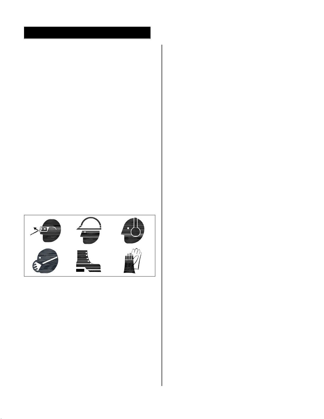
Examples of PPE include safety eyewear, safety hat,
hearing protection, dust mask, safety footwear, and
gloves. (Shown Pictograms of PPE is not all-
inclusive).
Those responsible for administering PPE shall train
personnel with the proper selection and use of PPE
to protect against misuse.
Safety Guards and Protective Barriers
A safety guard is a physical barrier designed to
prevent access to danger areas. Guards are tted to
the Allied equipment to protect against unsafe
situations that could not be eliminated through design
measures. Guards are only effective when properly
installed and in place. Guards shall not be removed
unless for the purpose of inspection and service of
components. Reinstall all guards after service or
adjustments are completed.
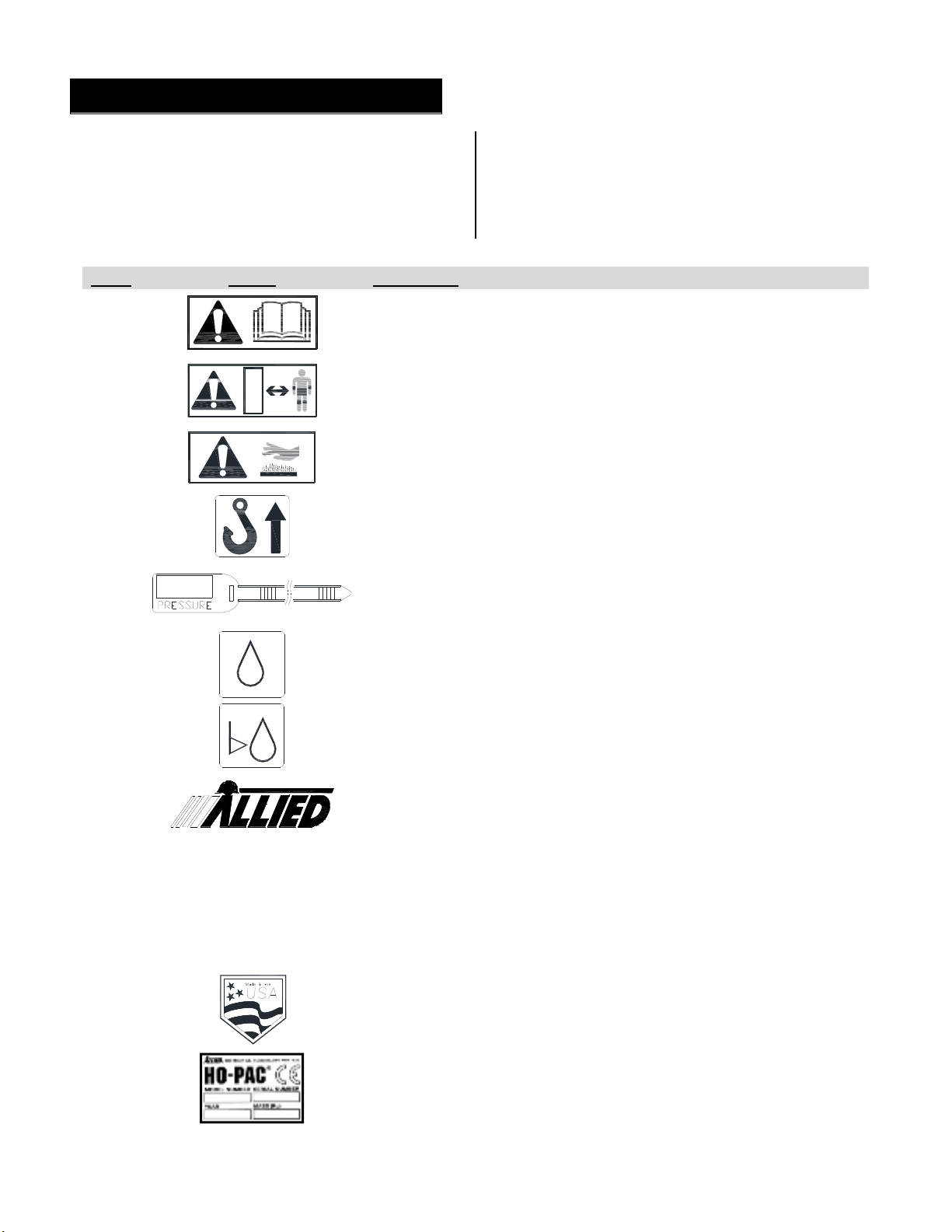
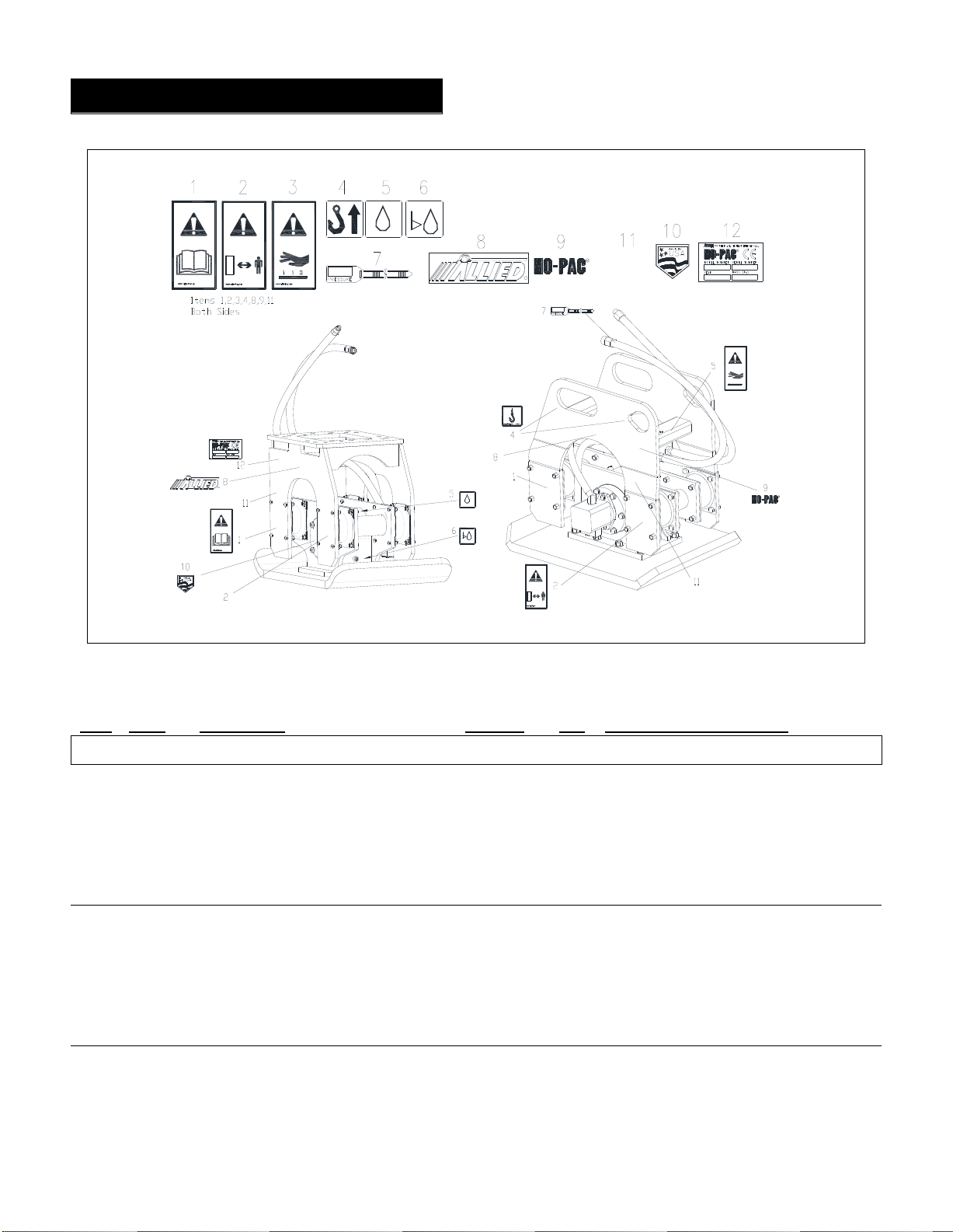
Where it was not possible to prevent an unsafe
situation by means of a guard, safety messages
appear on the equipment, warning personnel of a
recognized hazard.
Do not operate the work tool without proper guards
installed. Additional guarding, not included with the
Allied equipment, is necessary at the operator’s
station to protect the operator and other nearby
personnel against ying debris from material being
processed by the work tool.
Prevent accidental activation of the Allied work tool
by locating the control switch in a guarded area.
Compatibility and Use With Other Equipment
Allied work tools are designed to deliver satisfactory
performance with a broad range of carriers. In all
instances it rst must be conrmed through adequate
research and testing, that the equipment is suitable to
operate the Allied work tool. General specications
for this work tool, including the connecting
dimensions, can be found in the Technical Data
section of this manual and shall be strictly observed.
Careful review of the equipment’s specications
along with thorough knowledge of the system’s
operation, including hydraulic and electric is required.
If in doubt, and further assistance is required, it is the
responsibility of the equipment owner to contact their
authorized Allied dealer or Allied’s Product Support.
Unapproved Use or Modications
In order to provide and maintain efcient operation
with reliable service, while ensuring operator safety,
the Allied equipment may not be used for any
purpose other than, for which it was intended. Use of
the Allied equipment, other than those cited in this
manual, may place personnel at risk of injury and/or
may subject the equipment to damage.
When making repairs, use only the manufacturer's
genuine parts. Substitute parts may not meet the
required standards for t and quality, or may impair
function, safety and performance. The Allied
equipment shall not be modied or used in
unapproved applications unless written consent is
received from the Allied Engineering Department.

Allied Construction Products, LLC. www.alliedcp.com
viii
TM103337_HP1600_18feb
Table of Contents
SECTION Page
Contact Information & Document Revisions i
Important Safety Information……......…..…… ii
Table of Contents…………..…………...…….. viii
List of Figures….………………….…….…...… ix
1.0 Introduction & Scope……………..……… 1
1.1 About This Manual…………………………… 1
1.2 Purpose of This Manual…………..…….…. 1
1.3 How to Order Replacement Manuals…….… 1
1.4 Related Publications………………………... 1
2.0 Product Identication………………….….. 2
2.1 Where the Serial Number is Located..…… 2
2.2 Equipment Identication Tag…………..….. 2
2.3 Owner's Record of Identication Numbers 2
3.0 Warranty Protection Summary………...… 3
3.1 Overview…….…………………….…...…….. 3
3.2 Owner’s Responsibilities..………….……..... 3
3.3 Allied Product Policies………..…………….... 4
4.0 Product Information.………………….……. 5
4.1 Description and Intended Use………..…...… 5
4.2 Major Subassemblies….……………...……. 5
4.3 Principle of Operation…………….……..….. 5
4.4 Denition of Hydraulic Installation Terms… 6
5.0 Product Selection and Application Guide 6
5.1 Match Compactor Type to the Application 6
5.1.2 Match to Compatible Size Carrier……… 6
5.1.3 Other Considerations…………………….. 6
5.2 Auxiliary Hydraulic Circuit………………….. 6
5.3 Auxiliary Conversion Kits……………………. 6
6.0 Mounting Information….………………….. 7
6.1 Mounting Overview……………….…..….…. 7
SECTION Page
6.1.1 Flat Top Frame Mounting……..….……... 7
6.1.2 VMS Frame Mounting……………………. 8
7.0 Installation & Removal……………..…..… 9
7.1 Attach the Ho-Pac to Carrier ………….…… 9
7.2 Testing and Adjusting…………….….…….. 9
7.1.2 Tools Required to Attach the Ho-Pac…. 9
7.2 Connect Pressure and Return Lines…… 9
7.3 Removal from Carrier………………....…… 9
8.0 Operation..………………………..……..…… 12
8.1 Pre-operation Checks………….….…..…..… 12
8.2 Operation………………..…….…….………... 12
8.3 Compaction Handbook……………………… 13
9.0 Maintenance………………………..……….. 14
9.1 Maintenance…………………..…… 14
9.2 Maintenance Schedule Overview…………… 14
9.3 Conditional Maintenance……………..….… 14
9.2 Safety Precautions During Service………… 14
9.3 10 Hour (Daily) Maintenance……………….. 15
9.4 Carrier Oil Level & Quality….………….…… 15
9.5 Oil-lubricated Bearing System……………… 15
9.5.1 Vent Plug…………………………………… 15
9.5.2 Bearing Lubrication Oil Type & Capacity 16
9.5.3 How To Check Oil Level…………....…… 16
9.5.4 How To Add Oil…..…..…………….……. 16
9.5.5 How To Drain Oil………….….……. 17
9.6 How To Check Bearings……..……… 17
9.6.1 Bearing Replacement…….…..…... 17
9.6.2 Bearing Removal………….………. 17
9.6.3 Bearing Installation…………..….… 17
9.7 Spring Mount Replacement……....… 18
9.8 Tightening Torque……………….….. 24

Allied Construction Products, LLC. www.alliedcp.com
ix
TM103337_HP1600_18feb
Table of Contents - [cont’d]
SECTION Page
10.0 Lifting, Transport & Storage…………..... 20
10.1 Lifting & Transport……………...………….. 20
10.1.1 Transport Independently of Carrier…….. 20
10.1.2 Transport Attached to Carrier……….…. 20
10.2 Storage…….……………………………….. 20
11.0 Troubleshooting…………………….…... 21
12.0 Technical Data…………………....….…. 22
12.1 Testing the Hydraulic Circuit……….…..…. 22
12.2 Oil Pressure Check……….……….…..…. 22
12.3 Denition of Hydraulic Terms…………….. 22
12.4 Hydraulic Motor Options………………… 24
12.4.1 Motor Rotation………………………….. 24
12.4.2 Motor and Valve Combination………… 25
12.4.3 Control Valve Function………………… 25
12.4.4 Control Valve Adjustments…………… 25
12.4.5 Control Valve – Part Number………….. 25
12.5 General Specifications………………….. 26
13.0 Spare Parts Information…………… 26
13.1 General………………………………… 26
Table 13.1 Flat Top Assembly…….……. 29
Table 13.2 VMS-13 Assembly….…..……. 31
Table 13.2 VMS-16 Assembly……...……. 31
Table 13.3 Dynamic Assembly w/ Weld-on
Compaction Plate…………………………. 33
Table 13.4 Dynamic Assembly w/ Bolt-on
Compaction Plate SN1600&UP…………. 35
Table 13.5 Dynamic Assembly w/ Bolt-on
Compaction Plate SN1599&DOWN….…. 35
Table 13.6 Motor & Valve Options……....
List of Figures Page
S1 Safety Alert Symbol…………………… ii
S2 Safety Message Presentation - Typical ii
Equipment Identication Tag…………… iii
Lift Point………………………………….. iii
Stay Clear………………………………….. iii
Read Instructions…………………………. iii
Hot Surface……………………………….. iii
Model Identication……………………….. Iii
Pressure I.D……………………………….. Iii
Oil Fill……………………………………….. Iii
Oil Level……………………………………. iii
A, B Placement of Labels on Equipment… iv
Pictograms…………………………………. v
2-1 Location of Equipment Serial Number 2
2-2 Equipment Identication Tag…………. 2
4-1 Major Subassemblies……………...…. 5
4-2 Flow-Pressure Diagram…………..….. 6
5-1 1600 with Flat Top Frame.……….…... 8
5-2 1600 with VMS V-13 Top Frame..…… 9
5-3 1600 with VMS V-16 Top Frame…….. 9
6-1 Flat Top Mounting Frame……….…… 10
6-2 VMS Top Mounting Frame.……….…. 10
6-3 Mounting Bracket - Typical……..……. 11
6-4 VMS Mounting Components…………. 11
7-1 Hose Connections....………….………. 13
7-2 Hose Routing…………………………… 14
10-1 Location of Oil Fill & Level Plugs..….. 20
10-2 Proper Oil Level………………………. 20
10-3 Location of Oil Fill Plug…………….. 21
10-4 Flat Washer Position on Spring Mount… 22
10-5 Flow Valve Connection Markings.. 23
10-6 Flow Valve Connections…………… 23
10-7 CW Motor Rotation – Shaft End….. 23
12-1 Flat Top Assembly…………………. 28
12-2 VMS Assembly………………..……. 30
12-3 Dynamic Assembly w/ Weld-on
Compaction Plate………………………. 32
12-4 Dynamic Assembly w/ Bolt-on
Compaction Plate SN1600&UP……….…. 34
12-5 Dynamic Assembly w/ Bolt-on
Compaction Plate SN1599&DOWN….…. 36
12-6 Motor Identication…………..…….. 38
12-7 Valve Identication…………………. 38

Allied Construction Products, LLC. www.alliedcp.com
1
TM103337_HP1600_18feb
1.0 Introduction & Scope
1.1 About This Manual
All information contained herein, including text,
gures, captions, tables and descriptions is intended
solely for use with the product identied in Table 1.1.
Prior to its use, conrm that the information recorded
on the Equipment’s Identification Tag corresponds
with the model information located in Table 1.1.
Table 1.1 About This Manual
Document ID No. TM103337
Type Technical - Safety, Operation,
Maintenance and Parts
Current Status See Inside Cover
Product Name: Ho-Pac®
Generation III
Applicable Model[s]: 1600 Begin SN 01000
Years of Manufacture: Begin 2003
Material presented in this manual may show
equipment that is optional.
The content of this document has been reviewed for
accuracy. Allied Construction Products, LLC has
endeavored to deliver the highest degree of accuracy
and every effort has been made to provide
information as complete as possible. However,
continuous improvement of our products is an Allied
policy. The material in this publication, including
gures, captions, descriptions, remarks and
specications, describe the product at the time of its
printing, and may not reect the product in the future.
A summary of changes made to the content of this
document is provided on the inside cover.
1.2 Purpose of this Manual
This manual has been prepared in support of the
product named in Table 1.1 and is intended to assist
the operator and maintenance personnel with the
information necessary for the safe and proper use of
the Allied equipment.
This manual includes a spare parts list. Figures
shown in the Parts Information Section of this Manual
are for the purpose of parts identication and not
intended for use in the repair or service of the
equipment.
This document is published solely for information
purposes and should not be considered all-inclusive.
If further information is required, contact your local
Allied dealer or Allied Customer Service.
1.3 How to Order Replacement Publications
This manual is an integral part of this product. Keep it
in a convenient location so that it is easily accessible
for future reference.
Replacement manuals can be ordered by contacting
your local Allied dealer or Allied Customer Support.
See inside cover for contact information.
1.4 Related Publications
Related publications for the product identied in
Table 1.1 include the following:
1.4.1 Compaction Handbook 103392
The Compaction Handbook contains:
xBackground information about soil, soil
compaction and basic overview of different types
of soil compaction equipment.
xGeneral information about operating techniques
for vibratory plate compactors / drivers
xPerformance data for Ho-Pac models derived
from eld tests.
1.4.2 103467 Manual for Swivels (Option)
The optional swivel assembly allows the Ho-Pac to
index at either 45° or 90° to the carrier. Turning the
swivel is done manually.

Allied Construction Products, LLC. www.alliedcp.com
2
TM103337_HP1600_18feb
2.0 Equipment Identification
2.1 Location of the Serial Number
Fig. 2-1 Equipment ID Locations Identied
Refer to Figure 2-1. The Model and Serial Number
assigned to this equipment is found on the
Equipment ID Tag. The serial number is also
stamped in the housing weldment – motor side.
2.2 Equipment Identification Tag
Refer to Figure 2-2. The Equipment Identication Tag
is afxed to the top mounting frame. It provides the
following useful information:
xManufacturer’s Name and Address
xProduct name
xModel and Serial number
xYear of manufacture
xMass
Fig. 2-2 Equipment ID Tag
Verify that the information contained on the Tag
corresponds with the information provided in Section
1 of this manual.
2.3 Owner’s Record of the Equipment
Your local Allied dealer requires the Product Name,
Model and Serial Number to better assist you with
questions regarding parts, warranty, operation,
maintenance, or repair. This information should be
copied from the Equipment Identication Tag to the
space provided below.
Ho-Pac®Model 1600 X
Part number varies with top frame configuration
HP1600-FT Part No. 570319
HP1600-V13 Part No. 103350
HP1600-V16 Part No. 103360
Other
Serial Number:
In service date:
xIndicate the date in which the Allied equipment
was placed into service.
xReturn the completed Warranty Registration form
to Allied Construction Products, LLC.
Motor Option – GPM
25
30
43
34 End Serial No. 1399

Allied Construction Products, LLC. www.alliedcp.com
3
TM103337_HP1600_18feb
3.0 Warranty Protection Summary
3.1 Overview
The Allied work tool is delivered assembled,
lubricated, and factory tested. Upon receipt of the
equipment, inspect for possible shipping damage.
With all new Allied equipment, it is important to
complete all sections the Warranty Registration form
and return to Allied.
Warranty does not cover failures of the equipment
resulting from incorrect installation, misuse,
alterations by person other than authorized agents,
abnormal operating conditions, use of non-Allied
parts, unapproved service methods, or missed
maintenance requirements.
For details regarding warranty terms and conditions,
refer to document A100668.
3.2 Owner’s Responsibilities
When properly installed, operated and maintained by
qualied personnel, the Allied work tool will remain
productive with a minimum of service.
Keep the Allied equipment operating within its
performance limits by familiarizing yourself with the
specications provided in the technical data and
specications tables. Improper installation, including
failure to calibrate the carrier correctly may result in
loss of performance or subject the equipment to
conditions beyond their design.
The following outlines general maintenance policies
required for the Allied equipment. The owner is
strongly encouraged to adopt these general
guidelines and further develop them in order to
manage particular applications and operating
environments.
Ensure that personnel entrusted with installation,
operation, maintenance and transporting of the Allied
equipment adhere to the following:
xRead and thoroughly understand the information
and procedures detailed in this manual.
xUnderstand proper operating techniques for all
recommended applications.
xUse the Allied attachment only if it is in sound
operating condition. Take prompt action to rectify
any faults that, if left uncorrected, could lead to
personal injury or further damage.
xUse the Allied attachment only for the purpose for
which it is intended.
xUnderstand that particular applications, such as
when used as a driver, will require modifications
to the standard conguration along with
additional training for operators and service
personnel.
xAppoint Who Does What. Ensure that all
personnel understand what their specic
responsibilities include.
1. Establish maintenance responsibilities to be
performed by the OPERATOR.
2. Establish maintenance responsibilities to be
performed by the SERVICE TECHNICIAN.
xRecognize faults with the work tool and know
what corrective actions to take.
xConduct regular checks and inspections as
scheduled in the Care & Maintenance Section.
xAllow only qualied operators and Allied trained
service technicians to perform maintenance and
repair as specied in the care and maintenance
schedule.
xUse only genuine Allied replacement parts and
recommended lubricants to protect total warranty
coverage.
xMaintain written records of equipment
maintenance, service and repair. These records
are helpful if warranty coverage is ever in
question. Written records shall include at least:
xDate of service, maintenance or repair.
xDescription of the service, maintenance or
repair performed. Include part numbers if
applicable.
xCopies of purchase order(s) and invoice(s)
for repair parts and service.
xThe name and signature of the person
performing the service, maintenance or
repair.

Allied Construction Products, LLC. www.alliedcp.com
4
TM103337_HP1600_18feb
3.0 Warranty Protection Summary [cont’d]
3.3 Allied Product Policies
In this manual, Allied recommends the use,
applications, maintenance and service consistent
with industry practices.
Allied assumes no responsibility for the results of
actions not recommended in this manual and
specically the results of:
xImproper installation, set-up, calibration
xCarelessness / Incorrect operating methods
xInattention to re-lubrication and other
maintenance requirements
xMisuse / Unapproved applications
xInadequate or absence of training
xUse of non-genuine Allied replacement parts
xUnapproved modifications
xThe use of a lubricant type that is unsuitable for
the application.
xContaminated lubricants.
xImproper disposal of used or contaminated
lubricants.
The product is excluded from warranty if any of the
above conditions result in damage to the Allied
equipment, or the associated equipment or injury to
personnel. Such conditions will be determined by
Allied at its sole unfettered discretion.

Allied Construction Products, LLC. www.alliedcp.com
5
TM103337_HP1600_18feb
4.0 Product Information
4.1 Description
The Allied Ho-Pac® is a hydraulic powered, vibratory
plate compactor and driver. It is designed for
mounting on mobile equipment with hydraulic booms,
such as rubber tired or track-type construction
vehicles. The boom mounted Ho-Pac reaches out to
work anywhere the machine can reach and allows
the operator to keep a safe distance from the work
tool.
4.1.2 Application and Use - Typical
The Ho-Pac is used for soil compaction. Applications
include backll compaction, base course preparation,
nish surface treatment and embankment buildup.
The Ho-Pac can also be an effective sheet or pile
driver. Vibration energy is transferred through the
sheet or pile to the soil. Soils with 50% or more
granular content are “liquefied” by the vibration,
which breaks the skin friction, allowing the sheet or
pile to penetrate more easily. Further information is
available in the “Compaction Handbook”. To request
a copy, contact your local dealer or Allied’s Customer
Service. Ask for part number 103392.
4.2 Familiarization of Main Components
Fig. 4-1 Main Components Identied
1. Dynamic Assembly – Consists of the eccentric
mass, bearings and rubber springs. The housing
weldment with weld-on compaction plate is standard.
2. Suspension System – Rubber Springs mounted
between the Top Frame and Dynamic Assembly
isolate the vibratory energy from the carrier.
3. Top Frame – The Top Frame serves as the
connection point used to attach the Ho-Pac to the
stick / linkage of the carrier.
4. Control Valve – A multi-function valve is used to
control the motor. Benets include optimized
operation with improved reliability of critical
components such as the motor and bearings.
NOTE:The valve is factory pre-set and requires no
further adjustments.
The control valve performs the following functions:
xFlow regulator – Protects the bearings from
excessive loads by limiting oil ow that can over-
speed the hydraulic motor.
xPressure control – Protects the hydraulic
components from over-pressure. This is factory
pre-set at the maximum operating pressure plus
200 psi (14 bar).
xAnti-cavitation circuit - Protects the motor
against damage if the return circuit is not set up
with an unrestricted, free-flowing open return.
Also, controls deceleration of the hydraulic motor
and eccentric mass.
xReturn line check valve – Protects the motor
against damage from reverse ow. Also provides
a nominal back-pressure to ensure proper
operation of Allied’s AC40 and AC75 priority ow
control valves.
4.3 Principle of Operation
The vibratory action and impulse force are generated
from the hydraulic motor turning the eccentric mass
at a high rate of speed. Vibrating frequency and the
strength is affected by the rotation speed of the
motor, weight of the eccentric mass and the off-
center distance between eccentric mass and shaft.
The vibratory action and impulse force is transferred
through the attached compaction plate.
Efcient compaction of granular type soils is further
aided by the downward static pressure exerted by the
weight of the carrier pressing against the rubber
springs.

Allied Construction Products, LLC. www.alliedcp.com
6
TM103337_HP1600_18feb
5.0 Product Selection and Application Guide
5.1 Match Type of Compactor to the Application
The Allied Ho-Pac is a vibratory plate compactor,
designed for mounting on mobile equipment with
hydraulic booms, such as rubber tired or track-type
construction vehicles. It is best suited for compacting
granular type soils by combining three actions:
xImpulse Force
xVibration Frequency
xDown Pressure (Static Weight)
5.1.2 Match to Compatible Size Carrier
The Allied work tool is designed to provide
satisfactory operation with reliable service life when
teamed with a compatible carrier. Balance the size of
the Ho-Pac with the size of the carrier. If too small for
the carrier, the compactor will be damaged by the
carrier. Conversely, too large a compactor can
damage an undersized carrier.
5.1.3 Other Considerations
xReach - Select a carrier size having sufcient
reach to compact the deepest area of the trench
or excavation. This will also help minimize the
frequency of repositioning the carrier.
xLift Capacity - Know how your machine is
equipped and if any modications have been
made. Factors such as boom type, stick length,
undercarriage, tracks, counterweights, etc., all
affect the lifting capacity of the carrier. Also take
into account any add-ons, such as a quick attach
coupler. Consult the carrier manufacturer's
manual for specications.
xHydraulic Circuit - Select a carrier equipped
with a one-way hydraulic circuit and unrestricted
free owing return. It must maintain adequate
ow and pressure without loss of hydraulic power
to the Ho-Pac while the carrier applies down-
pressure. If not, motor speed slows and soil
density targets won't be reached.
Undersized compactors (as well as underperforming
compactors) are less economical to use because
compaction is limited to smaller lifts and require
additional passes. This generates other inefciencies
as longer running cycles result in loss of time,
increased energy consumption and component wear.
Optimum efciency is achieved only when proper
operating technique is employed. How many passes
it will take, along with the duration, will vary with
material type and lift. Additional ll material and
repositioning of the carrier may be required to
achieve a nished surface.
5.2 Auxiliary Hydraulic Circuit
CAUTION
Hydraulic circuits differ between
machines. Improper oil ow or pressure
can damage the Ho-Pac or carrier.
Only qualied personnel, having knowledge of the
machine’s systems, proper test equipment and tools
should perform conversion set-up and adjustments.
The Allied Ho-Pac is a hydraulic-driven work tool that
is not self-powered. Satisfactory performance centers
on the hydraulic circuit of the host machine to deliver
proper ow and pressure requirements.
Generally, most machines will require some degree
of conversion to make use of their hydraulic power.
Conversions to machines equipped with a factory or
dealer installed auxiliary circuit, however, may require
little more than minor adjustments to ow and
pressure settings.
Carefully follow all instructions, including those
provided by the machine manufacturer, when making
adjustments.
5.3 Allied Auxiliary Conversion Kits
Fig 5-1 Allied Conversion Kit with AC-Series Valve
Allied conversion kits are available for almost any
carrier. For machines without an auxiliary hydraulic
circuit, the kit may include an "AC" series valve.
These solenoid-operated valves will control ow and
pressure to the work tool.
Requests for further information or assistance with
Ho-Pac selection or conversion kits should be
directed to your Allied dealer or by contacting Allied
Sales or Product Support Departments.

Allied Construction Products, LLC. www.alliedcp.com
7
TM103337_HP1600_18feb
6.0 Mounting Information
6.1 Mounting Overview
Figures and descriptions represent standard
congurations.
Fig. 6-1 Mounting Bracket
Fig. 6-2 Flat Top Frame
The combination of Top Frame and mounting
components provide the connection point for
attaching the Ho-Pac to the carrier.
There are two types of top frames available:
xFlat Top (Fig. 6-2)
xVMS (Fig. 6-3).
6.1.1 Flat Top Mounting
The Flat-Top frame design includes a connection
plate for the bolt-on mounting bracket (Fig. 6-1).
Connection plates are grouped by size into Allied
mounting families. Dimensions of the plate, including
thickness, bolt hole spacing, diameter and quantity
will vary between mounting families. Connection
plates are typically designed to accommodate two
mounting families. Dimensions of the connection
plate can be found in the Technical Data section of
this manual.
Allied offers an array of bolt-on mounting brackets
(Fig. 6-1) to t virtually any carrier, including those
equipped with pin-grab or hook-type mounting
couplers.
IMPORTANT
The Ho-Pac does not include a mounting bracket.
Order separately. Bracket design is carrier
specic. The carrier’s bucket pins will be used
whenever possible. Ordering requires complete
information about the carrier, including make,
model, series and serial number. If equipped with
a quick coupler, additional information is required.
Make, model, series and serial number.
In Table 6.1, the mounting ‘Family’ designates a
sizing system used by Allied to identify various
connection plates. Flat top mountings are also used
on Allied’s hydraulic breakers.
Table 6.1 Mounting & Hardware for Ho-Pac 1600 with Flat Top
Family Model Bolt FL Washer Nut Bolt Set
SR
1600-FT
719815 3/4 x 3 ¾ (x8) 798064 (x16) 658839 (x8) 574820
MR 719520 1 x 3 ½ (x8) 719521 (x16) 620600 (x8) 574821
Follow proper tightening procedures and torque.

Allied Construction Products, LLC. www.alliedcp.com
8
TM103337_HP1600_18feb
6.0 Mounting Information [cont’d]
6.1.2 VMS (Variable Mounting System)
The VMS type frame (Fig. 6-3) is available as an
option. The variable mounting system offers the
combination of ease and versatility if the Ho-Pac is
transferred between multiple carriers.
Fig. 6-3 VMS Top Frame
Fig. 6-4 VMS Adjustable Combinations
The VMS is adaptable to most pin grabbing type
mounting couplers.
Components of a typical VMS kit are shown in Figure
6-5.
Fig. 6-4 VMS Mounting Components
1- VMS Top Frame (Not included with kit)
2- Collar
3- Plug
4- Mounting pin
5- Bolt, Nut
3
42
1

Allied Construction Products, LLC. www.alliedcp.com
9
TM103337_HP1600_18feb
7.0 Installation & Removal
7.1 Attach the Allied Equipment to Carrier
With the bucket removed and mounting bracket
bolted to the top frame, the Ho-Pac can be attached
to the carrier. Installation can vary, but the
procedures are similar to mounting a bucket. Use
standard mechanic’s techniques and tools.
7.1.2 Tools Required to Attach Ho-Pac to Carrier
No special tools are required, but the following tools
should be available:
xPPE including Safety eyewear & gloves
xSledge Hammer
xDrift pin / Alignment bar
x3/4 drive socket wrench
x3/4 drive metric sockets
xGrease gun
xStandard & Metric open end wrenches
xRags
xSuitable container to collect fluids
7.1.3 Install Procedure – Typical
CAUTION
Personal protection equipment required
when handling. PPE should include
appropriate clothing, gloves, safety
eyewear and shoes.
CAUTION
Both operator and assistant must be
qualied in handling procedures. The
operator must have an unobstructed
view of the assistant and load at all
times. The operator shall maintain
full control of the machine at all
times.
Crush hazard. Keep clear of crush
points and moving parts. All
directions and signals must be
agreed upon in advance. Take
signals from only ONE person.
The following describes basic procedures used to
attach the Ho-Pac to a machine equipped with a
typical pin on type mounting arrangement.
Procedures may vary and you should always follow
the instructions in the manual that is provided by the
carrier manufacturer. For carriers equipped with a
quick coupler, refer to the owner’s manual furnished
by the coupler manufacturer for instructions.
The machine operator and an assistant shall perform
the following procedure:
1. Operator: Move carrier and Ho-Pac to a rm level
surface. Position the Ho-Pac with the hose side
facing toward the carrier.
2. Assistant: Check that the Ho-Pac is stable and all
loads are supported.
3. Operator: Maneuver the stick in between lugging
of the mounting bracket. Align the stick pin holes
to the holes in the mounting bracket.
4. Assistant: Clean pins of rust and debris before
they are installed. Insert the stick pin and secure
with keepers.
5. Repeat procedure for installing link pin.
6. Lubricate pins.
7.2 Connect Pressure and Return Lines
CAUTION
Hydraulic circuits differ between
machines. Improper set up can
damage the Ho-Pac or carrier. Only
qualied personnel, having knowledge
of the machine’s systems should
install.
Identify whether the carrier's pressure line is located
on the right-hand or left-hand side. Do not guess. The
Ho-Pac will not operate if these hoses are crossed.
IMPORTANT
Read, understand and follow the instructions included
with the installation kit. The installation is not complete
until the hydraulic circuit is tested for ow and
pressure. Tools required for testing include a ow
meter and pressure gages. Test procedures, along
with a form to record the results of the ow test, can
be found in the Technical Data section of this manual.
Questions regarding testing procedures should be
directed to Allied Technical Service.
IMPORTANT
Contamination can diminish service life. Prevent
contaminating the oil. Always clean the area around
connections prior to opening the hydraulic system.

Allied Construction Products, LLC. www.alliedcp.com
10
TM103337_HP1600_18feb
7.0 Installation & Removal – [cont’d]
IMPORTANT
Collect uids in a suitable container. Clean up spilled
uids and obey all local regulations for the disposal
of these uids.
IMPORTANT
The Ho-Pac will not operate if supply and return
hoses are crossed.
Fig. 7-1 Supply Hose with Tag & Valve Identied
1. Connect Supply [IN] and Return [OUT] hoses to
carrier’s hydraulic circuit.
Fig. 7-2 Supply Hose, Valve & Motor Ports Identied
IMPORTANT
The control valve is attached to the top frame. The
part number of the valve can be found stamped into
the body above connection port T2.
2. Raise the work tool off the ground and operate
the bucket cylinder to ensure hoses will not be
pinched or restricted.
3. Briey test for proper operation. Tighten hoses
and connections as necessary.
Fig. 7-3 Check hose length & routing for unrestricted
movement
7.3 Removal From Carrier
CAUTION
Fluid penetration hazard. Release
pressure trapped in hoses before
disconnecting. Wear appropriate
protective equipment including safety
eyewear and gloves.
CAUTION
Both operator and assistant must be
qualied in handling procedures. The
operator must have an unobstructed
view of the assistant and load at all
times. The operator shall maintain
full control of the machine at all
times.
Crush hazard. Keep clear of crush
points and moving parts. All
directions and signals must be
agreed upon in advance. Take
signals from only ONE person.
Table of contents
Other Allied Power Tools manuals