Allis-Chalmers H 4 Specifications

OPERATORS
INSTRUCTIONS
FOR
MODEL H 4
&.
HD4
TRACTORS
ALLIS-CHALMERS
BOX
512 • MILWAUKEE, WISCONSIN 53201
LITHO.
IN
U.
S. A.
FORM
TM-387 A

.-----=:~~
DEALERS PRE-DELIVERY SERVICE
===~--,
MODEL H 4 & HD 4 TRACTORS
FIRM
NAME
____________
_
DATE
DELIVERED
____________
_
ADDRESS
_____________
_
SERIAL
#
PHONE
ENGINE #
_____________
_
THE
FOLLOWING
PRE·DEUVERY
SERVICE
HAS
BEEN
COMPLETED:
1.
LUBRICATED
2.
OIL
LEVEL
IN
GEAR
HOUSINGS
CHECKED
3.
ENGINE
OIL
LEVEl
CHECKED
4.
AIR
CLEANER
CHECKED
5.
FUEL
FIlTERS
CHECKED
6.
BATTERY
CHECKED
7.
COOLING
SOLUTION
IN
RADIATOR
CHECKED
s.
GENERATOR
CHARGE
RATE
CHECKED
9.
IGNITION
TIMING
CHECKED
10.
INJECTION
PUMP
TIMING
CHECKED
11.
CARBURETOR
CHECKED
12.
FAN
BELT
ADJUSTMENT
CHECKED
13.
CYLINDER
HEAD
TORQUE
CHECKED
14.
VALVE
TAPPET
ClEARANCE
CHECKED
15.
SPARK
PLUG
GAP
CHECKED
16.
ENGINE
SPEEDS
CHECKED
17.
STEERING
CLUTCH
ADJUST~ENT
CHECKED
18.
STEERING
BRAKE
ADJUSTMENT
CHECKED
19.
HYDRAULIC
SYSTEM
CHECKED
20.
ALL
BOlTS
&
NUTS
TIGHTENED
21.
LIGHTS
CHECKED
22.
TRACK
ADJUSTMENT
23.
APPEARANCE
OF
TRACTOR
* * *
YOLIR
TRACTOR HAS
BEEN
ADJlISTED
AND
SERVICED
BY
DEALER
PRIOR
TO
ITS
DELIVERY
TO YOLI.
YOLI
ARE
REQUESTED
TO ADVISE
WHEN
TRACTOR HAS OPERATED 30 DAYS (OR
100
HOURS)
SO
DEALER
REPRESENTATIVE
CAN
CHECK
ITS
ADJUSTMENTS
AND
PERFORMANCE.

DELIVERY
RECORD
FOR
FARM
OR
INDUSTRIAL
TRACTORS
THIS
FORM
MUST
se
FILtED OUT,
!N
TRIPLICATE, Sy
THE
DEALER
AND
SIGNED
BY
THE
CUSTOMER
AT
TIME UN!T
15
DELIVERED,
DELIVERED TO
_______________________
_
DEALER
R. R.
#
__________
_
BOX
#
______
_
TOWN
TOWN
___________________
___
SERIAL
#
STATE
_________________________
__ ENGINE #
PHONE
_________________________
_ SERVICED
BY
CHECK
ONE
fARM
USE
0
INDUSTRIAL
USE
0
EXPLAIN
CARE,
SAFE
OPERATION
AND
ADJUSTMENTS
OF
tTEMS
LISTED
BELOW:
TO
BE
COMPLETED:
o
LUBRICATION
o
BREAK-IN
PERIOD
o
STEERING
BRAKES
o
SHUTTLE
CLUTCH
BACKHOE;
o
ENGINE
TEMPERATURE
o
HYDRAULIC
SYSTEMS
MAKE
______
_
o
RADIATOR
DRAIN
COCKS
o
DRAWBAR
MODEl
______
_
o
RADIATOR
PRESSURE
CAP
o
fiNAL
DRIVE
SERIAL
No.
_____
_
o
fAN
BELT
o
TRANSMISSION
o
MOTOR
011
o
BATTERY
CARE
LOADER:
o
PROPER
fUEL
o
OIL
FILTERS
o
fUEL
filTERS
o
STARTING
MOTOR
o
AIR
ClEANER
o
LIGHTS
o
STARTING
8.
STOPPING
o
STORING
TRACTOR
MAKE
______
_
MODEl
_.
_____
_
SERIAL
No.
_____
_
o
GEAR
SHIFT
o
STEERING
CLUTCHES
o
TRACK
ADJUSTMENT
o
WINCH
DRIVE
o
OPERATORS
SAFETY
PRECAUTIONS
DOZERS;
MAKE
_______
_
MODEL
-:-:-:-
____
_
SERIAL
NO.
_____
_
REMARKS,
___________________________________________
___
OTHER
EQUIPMENT~
NAME
_____
_
MAKE
______
_
MODEL
______
_
SERIAL
No.
______
_
WARRANTY
.7
It
it
understood thai the AWs-Chalmers machinery
i~
$old
by
the Deoler with
the:
!otondord
warranty
of
the Manufacturer, set
forth
in full
on
page
one
of Ihe
Operators
Manual. This war-
ranty
is
the only warranty either express, implied.
or
statutory, upon which
laid
mQcbinery
is
told.
THIS
MACHINE
HAS
BEEN
DElIVERED
TO
ME
IN
GOOD
CONDITION
AND
I
HAVE
BEEN
INSTRUCTED
IN
ITS
CARE,
ADJUSTMENT
AND
SAFE
OPERATING
PRACTICES.
DELIVERED BY: Deoier
OWNER
BY:
Dole
OPERATOR:
-----------S~~~----------------------
Original
Copy
-fOR ALLIS-CHALMERS BRANCH

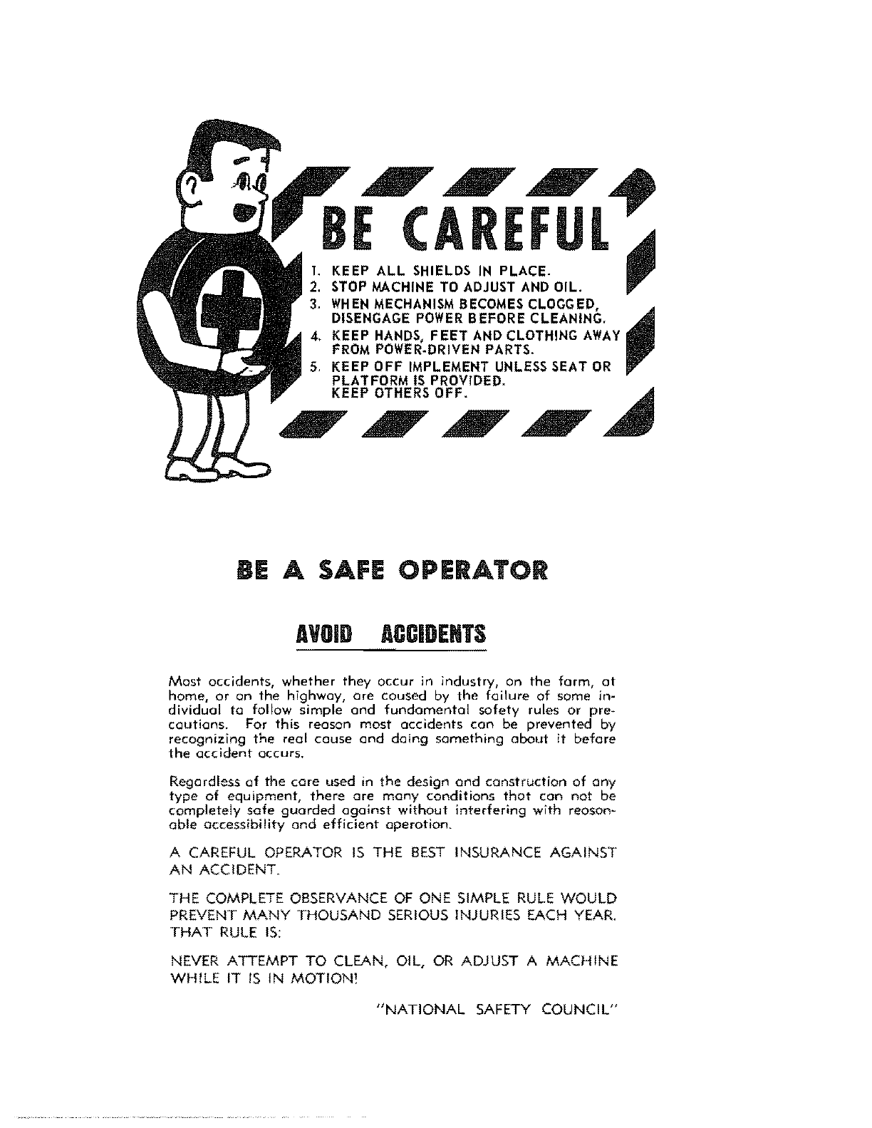
BE
CAREFUL
~
1.
KEEP
ALL
SHIELDS IN PLACE.
2.
STOP
MACHINE
TO
ADJUST AND OIL.
3.
WHEN
MECHANISM
BECOMES
CLOGGED,
~
DISENGAGE
POWER
BEFORE CLEANING.
KEEP HANDS, FEET AND CLOTHING
AWAY
FROM
POWER·
DRIVEN PARTS.
KEEP
OFF
IMPLEMENT UNLESS SEAT
OR
PLATFORM
IS
PROVIDED.
KEEP OTHERS OFF.
BE
A SAFE OPERATOR
AVOID
ACCIDENTS
Mast
accidents,
whether
they
occur
in
industry, on
the
farm,
at
harne,
or
an
the
highway,
are
caused
by
the
failure
of
Some in-
dividual
to
follow simple
and
fundamental
safety
rules or pre-
cQutions. For
this
reason
most
occidents
con
be
prevented
by
recognizing
the
real
couse
and
doing
something
about
it
before
the
occident
occurs,
Regardless
of
the
core used in
the
design
and
construction
of
any
type
of
equipment,
there
are
many
conditions
that
can
nat
be
completely
safe
guarded
against
without
interfering
with reason-
able
accessibility
and
efficient
operation.
A CAREFUL OPERATOR
IS
THE
BEST
INSURANCE
AGAINST
AN
ACCIDENT.
THE COMPLETE OBSERVANCE
OF
ONE SIMPLE RULE
WOULD
PREVENT
MANY
THOUSAND
SERIOUS
INJURIES EACH YEAR.
THAT
RULE
IS:
NEVER
ATTEMPT
TO CLEAN, OIL,
OR
ADJUST A
MACHINE
WHILE
IT
IS
IN
MOTION'
"NATIONAL
SAFETY
COUNCIL"

,
:
I
;
,
I
;
;
,
I
;
,
I
,
I
i
•
I
I
I
I
I
I
,
i
I
I
I
I
I
I
I
i
•
I
I
I
I
I
I
I
I
I
I
I
I
I
I
I
I
I
I
I
I
I
I
I
I
I
,
,
I
\
,
I
I
I
I
I
I
I
I
i
I
,
I
I
I
I
I
I
I
I
I
I
I
i
DELIVERY
RECORD
FOR
FARM
OR
INDUSTRIAL
TRACTORS
THIS
FORM
MUST
Sf
FlllED OUT, IN
TRIPLICATE,
BY
THE
DEALER
AND SIGNED
BY
THE
CUSTOMER
AT
TIME
UNIT
IS
DeLIVERED.
DELIVERED
TO
___________________
_
•.•.
#
_________
sox #
____
_
TOWN
__________________
_
TOWN
____________________
_
SERIAL
#
~
________________
_
STATE
____________________
__
ENGINE
#
___________________
_
PHONE
____________________
_ SERVICED
BY
______________________
_
CHECK
ONE
FARM
USE
D
INDUSTRIAL
USE
o
EXPLAIN
CARE,
SAFE
OPERATION
AND
ADJUSTMENTS
OF
ITEMS
LISTED
BELOW:
TO
BE
COMPLETED,
o
LUBRICATION
o
BREAK·IN
PERIOD
o
STEERING
BRAKES
o
SHUTTlE
ClUTCH
BACKHOE~
o
ENGINE
TEMPERATURE
o
HYDRAULIC
SYSTEMS
MAKE
______
___
o
RADIATOR
DRAIN
COCKS
o
DRAWBAR
MODEl
______
_
o
RADIATOR
PRESSURE
CAP
o
FINAL
DRIVE
SERIAL
No.
_____
_
o
fAN
BELT
o
TRANSMISSION
o
MOTOR
OIL
o
BATTERY
CARE
LOADER:
o
PROPER
FUel
o
OlL
FILTERS
o
FUEL
filTERS
o
STARTING
MOTOR
o
AIR
ClEANER
o
LIGHTS
D
STARTING
&
STOPPING
o
STORING
TRACTOR
MAKE
______
_
MODEl
______
_
SERIAL
No.
_____
_
o
GEAR
SHIfT
o
STEERING
ClUTCHES
o
TRACK
ADJUSTMENT
o
WINCH
DRIVE
o
OPERATORS
SAFETY
PRECAUTIONS
DOZERSJ
MAKE
_______
_
MODEl
______
_
SERIAL
NO.
____
_
REMARKS,
____________________________
_ OTHER EQUiPMENT:
NAME
______
_
MAKE
______
_
MODEL
_____
___
SERIAL
No.
____
_
WARRANTY
If
is
lJoclenfoQd
that
the Allis-Chalmers machinery
is
sold by
the
Dealer witn }he
standard
warrQnly
of
tn.
MOllvfocturer, Jet
fadh
in fvll
Of'!
page
one
of
the
Operators
Manual.
This
war-
fOnty
11
the
only
wortonly
elthu
eXprei$# implied,
or
dotutory,
upon which said machinery
is
sold.
THIS
MACHINE
HAS
BEEN
DELIVERED
TO
ME
IN
GOOD
CONDITION
AND
I
HAVE
BEEN
INSTRUCTED
IN
ITS
CARE,
ADJUSTMENT
AND
SAFE
OPERATING
PRACTICES.
DEUVERED
BY:
OWNER
BY:
OPERATOft:
__________
~~--------------------------
Srgnafure
2nd
Copy-FOR
DEALER'S
FlU
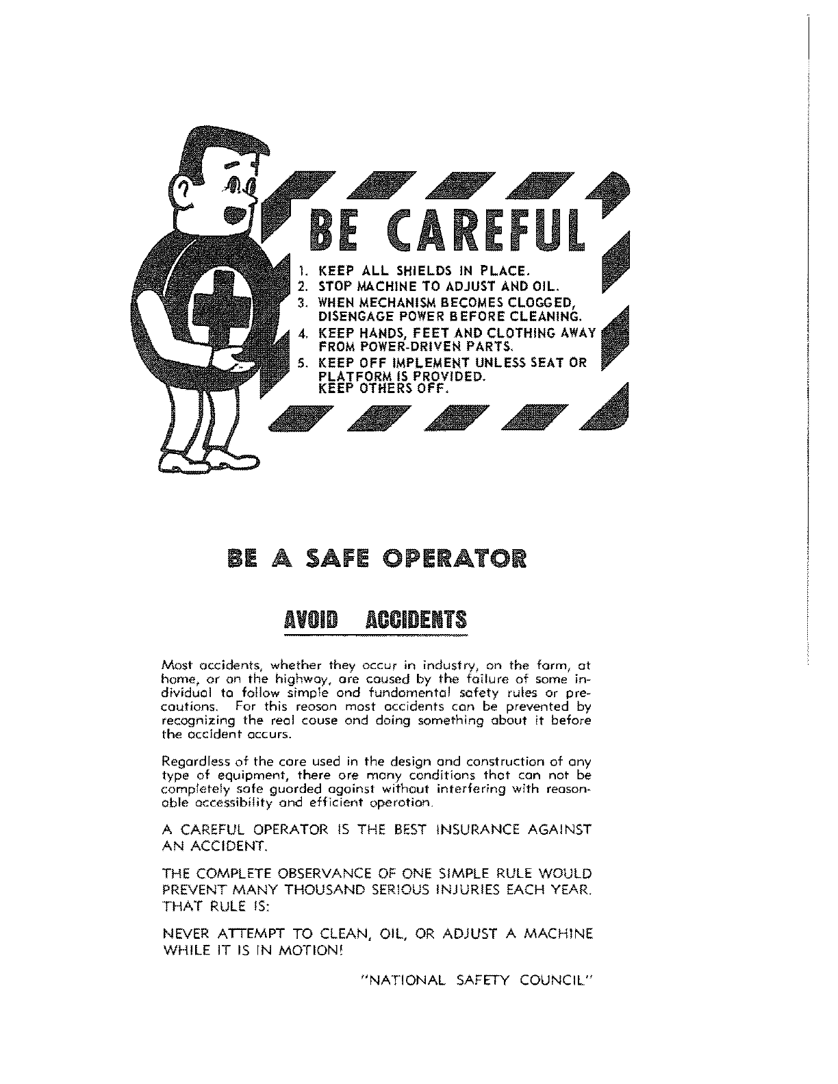
BE
"CAREFui"
1.
KEEP
ALL
SHIELDS IN PLACE.
~
2.
STOP
MACHINE
TO
ADJUST
AND
OIL.
".
3.
WHEN
MECHANISM
BECOMES
CLOGGED,
~
DISENGAGE
POWER
BEFORE CLEANING.
KEEP
HANDS,
FEET AND CLOTHING
AWAY
FROM
POWER·DRIVEN PARTS.
KEEP OFF IMPLEMENT UNLESS SEAT
OR
PLATFORM
IS
PROVIDED.
KEE,OFF.
~
~
BE
A SAFE OPERATOR
AVOID
ACCIDENTS
Most
accidents,
whether
they
OCCur
in industry, on
the
farm,
at
home,
or
on
the
highway,
are
caused
by
the
failure
of some in-
dividual
to
follow
simple
and
fundamental
safety
rules or pre-
cautions.
For this
reason
most
accidents
can
be
prevented
by
recognizing
the
real
cause
and
doing
something
about
it
before
the
accident
occurs.
Regardless
of
the
care
used
in
the
design
and
construction
of
any
type
of
equipment,
there
are
many
conditions
thot
can
not
be
completely
safe
guarded
against
without
interfering
with reOson-
able
accessibility
and
efficient
aperation.
A CAREFUL
OPERATOR
IS
THE
BEST
INSURANCE AGAINST
AN
ACCIDENT.
THE COMPLETE OBSERVANCE
OF
ONE SIMPLE
RULE
WOULD
PREVENT
MANY
THOUSAND
SERIOUS
INJURIES EACH YEAR.
THAT
RULE
IS:
NEVER
ATTEMPT TO CLEAN, OIL,
OR
ADJUST A
MACHINE
WHILE
IT
IS
IN
MOTION!
"NATIONAL
SAFETY COUNCIL"

DELIVERY
RECORD
FOR
FARM
OR
INDUSTRIAL
TRACTORS
THIS
FORM
MUST
BE
FILLED
OUT,
IN
TRIPLJCA1f~
BY
THE
DEALER
AND
SIGNED
BY
THE
CUSTOMER
AT
TIME
UNIT
IS
DElIVERED.
DELIVERED
TO
_________________
_
DEALER
R.
R.
#
__________
BOX
#
____
_
TOWN
TOWN
____________________
_
SERIAL
#
STATE
____________________
_
ENGINE
#
PHONE
____________________
_ SERVICED
BY
CHECK
ONE
FARM
USE
0
INDUSTRIAL
USE
EXPLAIN
CARE,
SAFE
OPERATION
AND
ADJUSTMENTS
OF
ITEMS
LISTED
BelOW:
o
LUBRICATION
o
STEERING
BRAKES
o
BREAK-IN
PERIOD
o
SHUTTLE
CLUTCH
o
ENGINE
TEMPERATURE
o
HYDRAUliC
SYSTEMS
o
RADIATOR
DRAIN
COCKS
o
DRAWBAR
o
RADIATOR
PRESSURE
CAP
o
FINAL
DRIVE
o
FAN
BELT
o
TRANSMISSION
o
MOTOR
OIL
o
BATTERY
CARE
o
PROPER
FUEL
o
AIR
CLEANER
o
OIL
FILTERS
o
LIGHTS
o
FUEl
FILTERS
o
STARTING
&
STOPPING
o
STARTING
MOTOR
o
STORING
TRACTOR
o
GEAR
SHIFT
o
TRACK
ADJUSTMENT
o
STEERING
CLUTCHES
o
WINCH
DRIVE
o
OPERATORS
SAFETY
PRECAUTIONS
REMARKS:
___________________________
_
WARRANTY
0
TO
BE
COMPLETED:
BACKHOE:
MAKE
_______
_
MDDEL
______
_
SERIAL
No.
_____
_
LOADER:
MAKE
______
___
MODEL
______
_
SERIAL
No.
_____
_
DOZERS:
MAKE
MODEL-------
SERIAL
NO.
____
_
OTHER EQUIPMENT:
NAME
______
_
MAKE
______
_
MODEl
____
-------
SERIAL
No.
____
_
It
is
IJrtderstood
that
the
AIIi$-Cholmers machinery
is
sofd by
the
Dealer
wHh
tn
....
standord
warronty
of
the
Mortufoctufil't,
set forth in full on
page
one
of
the
Operators
Manual.
This
wor~
ronty
IS
fhl'(O
only
worro."y
either
expreu,
implied,
or
statutory,
upon
which soid machinery is sold.
THIS
MACHINE
HAS
BEEN
DELIVERED
TO
ME
IN
GOOD
CONDITION
AND
I
HAVE
BEEN
INSTRUCTED
IN
ITS
CARE,
ADJUSTMENT
AND
SAFE
OPERATING
PRACTICES.
DELIVERED
BY:
Deoler
OWNER
BY,
________________________________
~-------
Dole OPERATOR:
__________
~~~~----------------------
3rd
Copy
-FOR CUSTOMER
BE
CAREFUL
1.
KEEP
ALL
SHIELDS IN PLACE.
~
2.
STOP
MACHINE
TO
ADJUST
AND
OIL. "
3.
WHEN
MECHANISM BECOMES CLOGGED,
~
DISENGAGE
POWER
BEFORE CLEANING.
KEEP HANDS,
FEET
AND CLOTHING
AWAY
FROM
POWER-DRIVEH PARTS,
KEEP OFF IMPLEMEHT UNLESS SEAT
OR
PLATFORM
IS
PROVIDED,
KEEP OTHERS OFF.
IE
A SAFE OPERATOR
AVOID
ACCIDENTS
Most
accidents,
whether
they
occur
in industry,
on
the
farm,
at
home,
or
on
the
highway,
are
caused
by
the
failure
of
some in-
dividual to fallow
simple
and
fundamental
safety
rules or pre-
cautions.
For
this
reoson
most
accidents
con
be
prevented
by
recognizing
the
real
cause
and
doing
something
about
it before
the
occident
occurs.
Regardless
ot
the
care
used
in
the
design
and
construction
at
any
type
of
equipment,
there
are
many
conditions
that
can
not
be
completely
sate
guarded
against
without
interfering
with reason-
able
accessibility
and
efficient
operotion.
A CAREFUL OPERATOR
IS
THE
BEST
INSURANCE AGAINST
AN
ACCIDENT,
THE COMPLETE OBSERVANCE
OF
ONE SIMPLE
RULE
WOULD
PREVENT
MANY
THOUSAND
SERIOUS
INJURIES EACH YEAR,
THAT
RULE
IS:
NEVER ATTEMPT
TO
CLEAN, OIL,
OR
ADJUST A
MACHINE
WHILE
IT
IS
IN
MOTION'
"NATIONAL
SAFETY
COUNCIL"
FOREWORD
This
book
is
written
for
the
purpose
of
providing
the
essential
information
regarding
the
day-to-day
care,
lubrication
and
adjustment
of
the
tractor.
Economical
operation
will
be
assured
if
these
instructions
are
followed*
The
instructions
given
in
this
book
cover
the
operation
of
the
Allis-Chalmers
H4
and
HD4
Standard
Tractors.
A
close
adher-
ence
to
these
instructions
will
result
in
many
hours
of
trouble-
free
operation
and
a
longer
operating
life
for
the
unit.
This
If
Green
Cross
for
Safety
I I
is
used
in
book
to
emphasize
safety
precautions
that
should
be
followed
by
operator
to
avoid
accident
and
possible
injury.
Where
you
see
this
emblem
heed
its
warning.
This
HGreen
Cross
for
Safetyll
is
used
only
by
lllembers
of
the
National
Safety
Council.
Many
OWners
of
Allis
-Chalmers
equipment
employ
the
Dealer!
s
Service
Department
for
an
work
other
than
routine
care
and
adjustments.
This
practice
is
encouraged
as
our
dealers
are
kept
well
informed
by
the
factory
regarding
advanced
methods
of
servicing
Allis-Chalmers
products
and
are
equipped
to
ren-
der
satisfactory
service.
To
assure
the
best
results
and
to
main:ain
the
original
quality
built
into
the
tractor,
it
is
important
that
Anis-Chalmers
Parts
be
used.
WARRANTY
ALLlS·CHALMERS
MANUFACTURING COMPANY Ithe Company) worrants
ito
new machinery
covered by this
order
or
contract
(excluding tires
and
B~Series
engines
and
engine accessories which
ore
warranted
by
the
respective monufocturers only)
to
be free
of
defects in workmonship
and
material
at
the
time
of
shipment
from
the
Company's factory.
This warranty
is
the
only warronty upon which
the
Companis
new machinery
is
said,
NO
OTHER
WARRANTY
SHALL
BE
IMPLIED
AND
ALL
STATUTORY
WARRANTIES
SHALL
BE
DEEMED
WAIVED.
No warranty
of
any kind, statutory, implied, or otherwise,
IS
mode
with
respect to second-hand machinery
or with respect to
new
machinery which,
after
shipment
from
the
Compony~s
factory, has been altered,
repaired
or
treated
in
any
manner
whatsoever.
The Company
will
repair or replace f.o.b, its factory
any
port
in
its new mochinery which under
normal use foils within twelve months (except six months instead of twelve months
in
the
case of products
of
the
Springfield
and
Deerfield Works
of
the
Company
and
engines sold
as
power
units,
from
dote
of
delivery
of
such machinery
to
the
first user/ proVided
that
the
Company is promptly notified thereof
and
that
the
port
is
returned
to
the
Company
or
to
an
authorized
dealer
properly identifred, charges prepaid!
and
is found to
the
satisfaction of
the
Company to have been defective in workmanship or material
at
the
time
af
shipment
of
the
machinery from
the
factory
as
aforesaid.
The
Company's liability
whether
in
contract
ar
in
tort
arising
out
of warranties; representations,
instructions, or defects from
any
cause
shall be limited exclUSively to repairing or replacing under the
canditians as aforesaid.
No representotlve
af
the
Company has outnority to
change
this warranty
and
no
attempt
ta
repair or premise to repair or improve
the
machinery by any representative
of
the
Company snail
change
or extend this warranty.
1
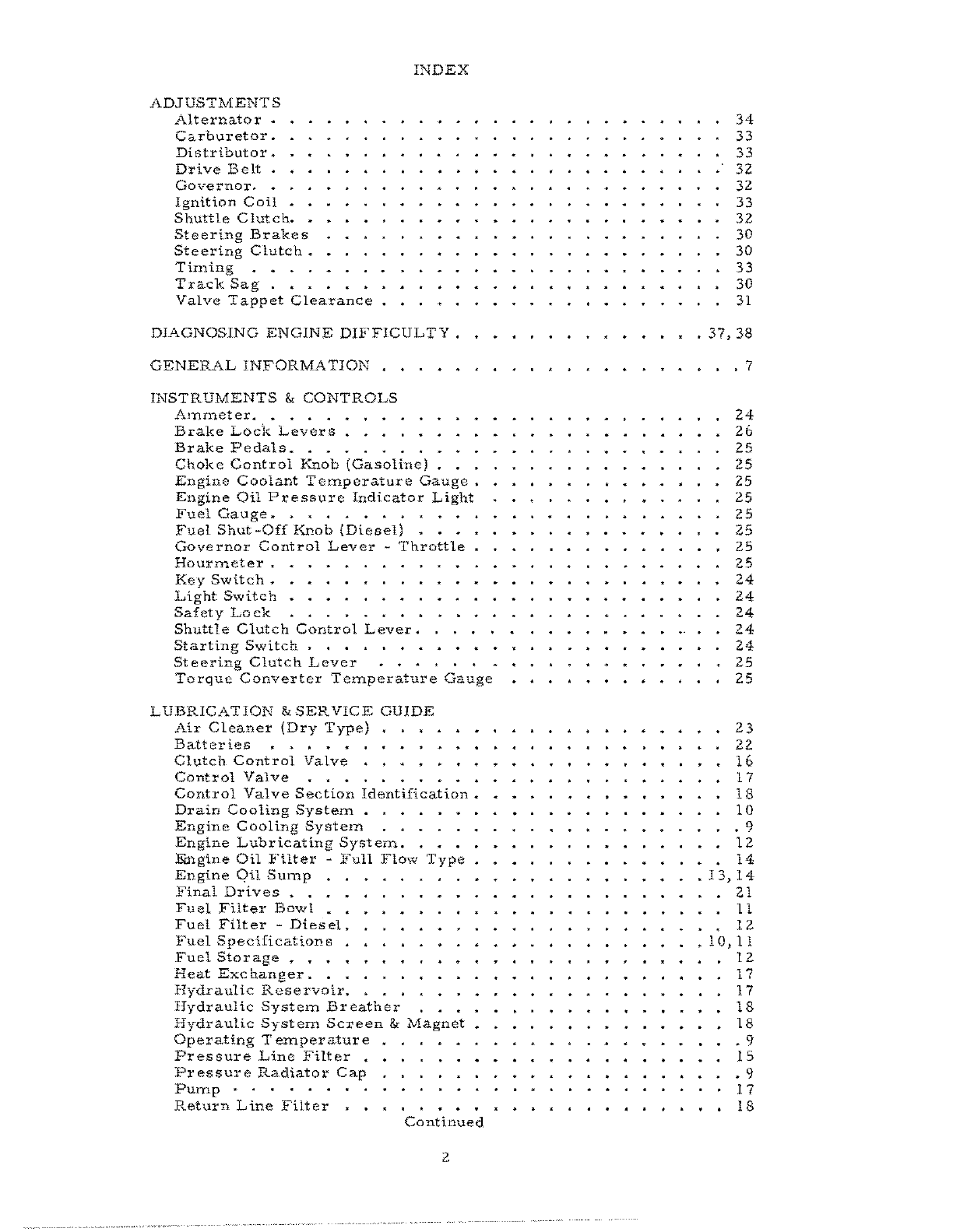
I~DEX
ADJUSTMENTS
Alternator
~
Carburetor.
Distributor
~
Drive
Belt.
Governor.
.
Ignition
Coil
Shuttle
Clutch.
Steering
Brakes
Steering
Clutch.
Timing
....
Track
Sag
.•.
Valve
Tappet
Clearance
DIAGNOSING
ENGINE
DIFFICULTY.
GENERAL
INFORMATIOK
.•
INSTRUMENTS'"
CONTROLS
AlTImeter
.....
Brake
Lock
Levers.
. . .
Brake
Pedals
••••.••
Choke
Control
Knob
(Gasoline)
Engine
Coolant
Temperature
Gauge.
Engine
Oil
Pressure
Indicator
Light
Fuel
Gauge.
• • . . • • • • • •
Fuel
Shut-Off
Knob
(Diesel)
•••
Governor
Control
Lever
~
Throttle
Hourmeter.
Key
Switch.
Light
Switch
Safety
Lock
Shuttle
Clutch
Control
Lever.
Starting
Switch
. . . . . . .
Steering
Clutch
Lever
Torque
Converter
Temperature
Gauge
LUBRICATIOK
&
SERVICE
GUIDE
Air
Cleaner
(Dry
Type)
Batteries
Clutch
Control
Valve
Control
Valve
Control
Valve
Section
Identification.
Drain
Cooling
System
. . .
Engine
Cooling
SystelTI
. • • . .
Engine
Lubricating
System
....
Eingine
Oil
F'ilter
-
Full
Flow
Type
Engine
QU
SUlnp
Final
Drives
. .
Fuel
Filter
Bowl
Fuel
Filt
er
-
Dies
el
.
Fuel
Specifications
Fuel
Storage
•.•.
Heat
Exc
hanger.
. .
Hydraulic
Reservoir.
Hydraulic
System
Breather
Hydraulic
System
Screen
&
Magnet
Operating
Temperature
Pressure
Line
Filter
.
Pressure
Radiator
Cap
Pump·
.•.•.
Return
Line
Filter
Continued
2
34
33
33
32
32
33
32
30
30
33
30
31
·
37,
38
• • • 7
24
26
25
25
25
25
25
25
25
25
24
24
24
24
24
25
25
23
22
16
17
18
10
• 9
12
14
•
13,14
21
II
12
•
10,11
12
17
17
18
18
· 9
15
• 9
17
18

Spark
Plugs.
. . .
Suction
Line
Filter.
Temperature
Gauge
Torque
Converter
.
INDEX
(Cont'd)
Torque
Converter
&
Shuttle
Clutch.
Torque
Housing
. . . .
Track
Idlers
&
Rollers.
Track
Support
Idlers
Transmission.
~
...
LUBRICA
TION
&
SERVICE
INSTRUCTIONS
OPERATING
INFORMATION
Check
Oil
Pressure
.
Degree
Slope
•
Diesel
Starting
Fluid.
Down
Hill.
• . . . .
Fast
Warm-Up
Gear
Shifting
-
Transmission
Shuttle
Clutch
Hydraulically
Operated
Starting
&
Stopping
Engine
Steering
of
Tractor
Track
&
Track
Shoes
SAFETY
PRECAUTIONS
SERVICE
&
LUBRICATION
LOCATION
GUIDE
SPECIFICATIONS
WIRING
DIAGRAMS
3
·
22
•
15
·
17
•
17
•
14
.17
• 21
· 21
·
21
· 8
.26
.28
.27
•
28
2.6,27
•
.28
• •
28
2.6,27
• 28
•
29
6
8
4
..35,36

ENGINE
Model.
Make.
Type.
Number
of
cylinders
Bore
......•
Stroke
• . • . . •
No.
of
Main
Bearings.
Piston
Displacement
Compression
Ratio
COlnpression
Firing
Order.
. •
Low
Idle
• . • .
Governed
@
Full
Load.
High
Idle
. . . • •
Fuel
Injection
Pump
Carbul'
eto!'
Nozzle
Holder
Valves
Intake
Clearance.
Exhaust
Clearance
~
Battery
• •
Type
.•
Volts.
.
Capacity
Quantity
Terminal
Ground
Circuit
Starter
.
Spark
Plugs
Thl'
ead
Size.
Reach
Gap
Heat
Range
Distributor
Make
••
Point
Gap.
Advance
Advance
Timing
GENERAL
SPECIFICATIONS
DIESEL
.
D2200
.
Allis
-Chalmer
s
.4
cycle
naturally
aspirated
4
3.88
4.2.5"'
5
200
Cll.
in.
16.25:1
500
PSI
@600
RPM
1-3-4-2
650-700
RPM
2100
RPM
2250-2310
RPM
Roosa
Master
Model
DBGFC
437-7AF
TiITIed
@
28°
BTDC
GASOLINE
G2200
Allis-Chalmers
4
cycle
naturally
aspirated
4
3.88
4.25"
5
200
cu.
in.
8.15:1
165
PSI@
150
RPM
1-3-4-2
450-500
RPM
2100
RPM
2300-2325
RPM
. . •
Zenith
Model
267
JX9
Opening
Pressure
2750
PSI
.015"
.015"
Standard
2-135
6
135AH
2
Neg.
Parallel
Optional
30H95
12
190
AH
2
Neg.
Series
Delco
Remy
111107589
4
.020"
.02.5"
Standard
24-53
12
53AH
1
Neg.
Optional
30H-95
12
95AH
1
Neg.
Delco
Remy
111107356
14MM
3/4"
.025"
AC
45
XL
Autolite
AG5A,
Champion
N8
Delco
Remy
111112665
.016"
Automatic
28
0
BTDC
@
2100
RPM
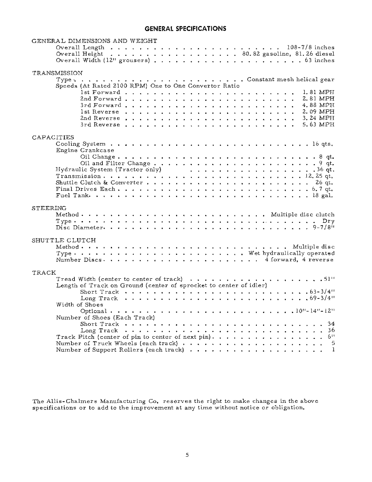
GENERAL
SPECIFICATIONS
GENERAL
DIMENSIONS
AND
WEIGHT
Overall
Length
• • • . • •
Overall
Height
• • • . • •
Overall
Width
(12"
grousers)
TRANSMISSION
Type
'.
Speeds
(At
Rated
2100
RPM)
One
to
1st
Forward
2nd
Forward
3rd
Forward
1st
Reverse
2nd
Reverse
3rd
Reverse
CAPACITIES
Cooling
System
• •
Engine
Cr
ankca
s e
Oil
Change.
Oil
and
Filter
Change
Hydraulic
System
(Tractor
only)
Transmission
.••.•
4
Shuttle
Clutch
&
Converter
Final
Drives
Each
..
Fuel
Tank.
• . • • • • •
STEERING
Method.
Type
...
Disc
DialTlcter.
SHUTTLE
CLUTCH
Method
•••
Type
.•.•
Number
Discs.
TRACK
One
Convertor
Ratio
. . • •
•.
108-7/8
inches
80.82
gasoline,
81.
26
diesel
••.••.•••
63
inches
Constant
mesh
helical
gear
1.
81
MPH
2.81
MPH
4.88
MPH
2.09
MPH
3.24
MPH
5.63
MPH
16
qts.
• 8
qt
•
• 9
qt.
.36
qt.
12.25
qt.
26
qt.
6. 7
qt.
18
gal.
Multiple
disc
clutch
• •
Dry
•
.•••.
9-7/8"
. • • • • •
Multiple
disc
Wet
hydraulically
operated
4
forward,
4
reverse
Tread
Width
(center
to
center
of
track)
.•••
Length
of
Track
on
Ground
(center
of
sprocket
to
Short
Track
center
of
idler)
Long
Track
Width
of
Shoes
Optional.
•
Number
of
Shoes
(Each
Track)
Short
Track
• • • •
Long
Track
• • • . •
Track
Pitch
(center
of
pin
to
center
of
next
pin)
.
Number
of
Truck
Wheels
(each
track)
•
Number
of
Support
Rollers
(each
track)
••••
.63-3/4"
•
69-3/4"
34
36
6"
5
I
The
Allis-Chalmers
Manufacturing
Co.
reserves
the
right
to
make
changes
in
the
above
specifications
or
to
add
to
the
irnprovement
at
any
time
without
notice
or
obligation.
5

(9
SAFETY
PRECAUTIONS
f)
Many
hours
of
lost
time
and
much
suffering
is
caused
by
the
failure
to
practice
simple
safety
Tules.
IT
IS
TOO
LATE
TO
REMEMBER
WHAT
SHOULD
HAVE
BEEN
DONE
AFTER
THE
ACCIDENT
HAS
HAPPENED.
1.
Do
not
fill
fuel
tanks
when
engine
is
hot
or
while
using
a
lantern
or
when
smoking.
2~
Do
not
attempt
to
oil
or
grease
a
machine
Or
tractor
while
it
is
in
operation~
3~
Do
not
wear
loose
fitting
clothing
that
may
be
blown
into
nloving
parts.
4.
Keep
all
shields
and
guards
in
place.
5.
Place
gear
shift
lever
in
neutral
position
when
starting
engine
or
dismounting
from
tractor.
6.
Machinery
should
be
only
operated
by
those
who
are
responsible
and
delegated
to
do
so.
7.
Only
one
person
-
the
operator
-
should
be
permitted
on
tractor
when
it
is
in
motion.
8.
The
rate
of
travel
on
hillsides
or
curves
should
be
regulated
so
there
is
no
danger
of
tipping.
9.
Do
not
remove
radiator
cap
when
engine
teITlperature
is
above
2lZoF.
10.
Steering
brakes
and
clutches
should
be
pro-
perly
adjusted.
11.
Do
not
drive
too
close
to
the
edge
of
a
ditch
12*
Never
operate
your
tractor
in
a
closed
gar-
age
Or
shed.
13.
When
tractor
is
hitched
to
a
stump
Or
other
heavy
loads,
always
hitch
to
drawbar
and
never
take
up
slack
in
chain
with
a
jerk.
14.
Always
keep
tractor
in
gear
when
going
down
steep
grades.
15.
Do
not
leave
the
engine
running
unattended
when
anyone
is
adjusting
or
repairing
a
driven
machine.
16.
Do
not
atterr;pt
to
operate
tractor
unless
you
are
in
the
driver1s
seat.
17.
Provide
a
first
aid
kit.
Treat
all
scrate
hes.!
cuts,
etc.,
with
the
proper
antiseptic
immediately.
18.
Never
stand
between
tractOr
and
drawn
im-
plement
when
hitching.
Use
an
iron
hook
to
handle
drawbar.
19.
Do
not
dismount
from
tractor
while
it
is
in
nlotion.
20.
Keep
a
fire
extinguisher
handy
at
all
times.
21.
Lock
shuttle
clutch
lever
in
neutral
position
when
dismounting
tractor.
UNDER
NO
CIRCUMSTANCES
SHOULD
ANYTHING
BE
PULLED
FROM,
HOOKED
TO
ANY
PART
OF
THE
TRACTOR
EXCEPT
THE
DRAWBAR.
OR
BE.
6
GENERAL
INFORMATION
The
standard
Model
tractor
is
available
with
either
a
gasoline
engine,
H4,
or
a
Diesel
engine,
HD41
which
are
naturally
aspirated,
open
combustion
chaInber
engines.
Power
from
the
engine
is
transmitted
through
the
torque
converter
and
to
a
constant
mesh
helical
gear
transmis
sion.
From
the
trans-
rnission
the
power
is
transmitted
to
the
spiral
bevel
gear
and
from
the
spi
ral
bevel
gear
through
the
multiple
disc
steering
clutches
to
the
final
drives
and
the
track
sprockets.
The
trans-
mission
provides
3
forward
speeds,
1.81
M.P.H.
in
1st;
2.81
M.P.H.
in
2nd
and
4.88
M.P.H.
in
3rd;
and
3
reverse
speeds
of
2.09
M.P.H.
in
1st;
3.24
M.P.H.
in
2nd
and
5.63
M.P.H.
in
3rd,
at
rated
engine
speed
of
2100
RPM,
and
1
to
1
converter
ratio~
The
standard
tractor
is
equipped
with
electric
starting
and
panel
lighting
equipment,
suction
type
cooling
fan
mounted
in
center
of
tractor,
muffler,
dry
type
air
cleaner
t
torque
con-
verter
J
neces
sary
gauges
and
sending
units
~
Fot'
a
complete
listing
of
all
available
equipment
consult
your
local
Allis-Chahners
dealer.
~
______________________________
FIG.
1
______________________________
~
SERLt"L
NUMBER
LOCATIONS
NOTE:
On
all
parts
orders
and
in
all
corres-
pondence
relative
to
the
tractor,
it
is
necessary
that
both
the
tractor
and
engine
Serial
Numbers
be
given.
This
will
properly
identify
the
parti-
cular
unit
and
will
assure
obtaining
correct
re-
placement
parts
for
it~
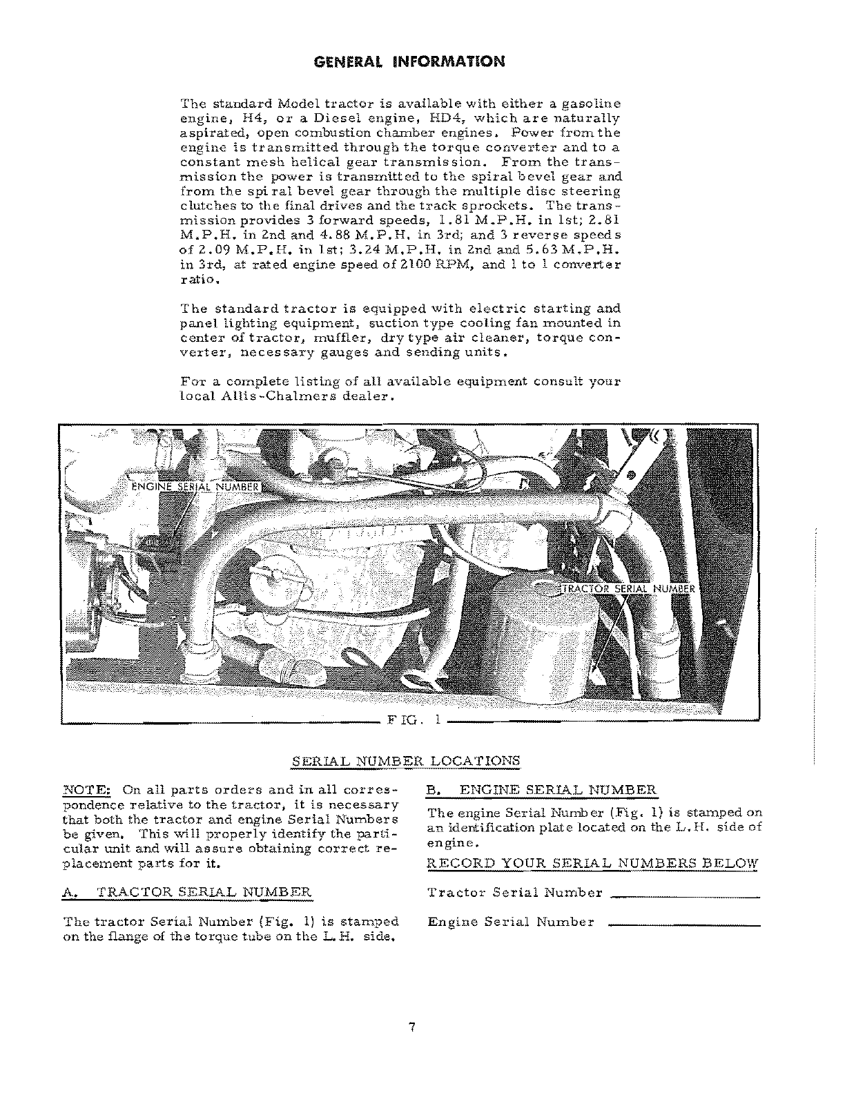
A.
TRACTOR
SERIAL
NUMBER
The
tractor
Serial
Number
(Fig.
1)
is
stamped
on
the
flange
of
the
torque
tube
on
the
L
H~
side~
7
B.
ENGINE
SERIAL
NUMBER
The
engine
Serial
Number
(Fig.
1)
is
stamped
on
an
identHication
plate
located
on
the
L.
H.
side
of
engine.
RECORD
YOUR
SERIAL
NUMBERS
BELOW
Tractor
Serial
Number
Engine
Serial
NUlllber

LUBRICATION
&.
SERViCE
INSTRUCTiONS
To
prevent
minor
irregularities
from
developing
into
serious
conditions
that
might
invo
lye
shut-
do'h'11
and
rna.jor
repair,
several
other
checks
and
services
must
be
included
at
the
same
intervals
as
lubrication.
These
checks
and
services
will
reveal
the
need
for
adjustment
or
change
due
to
normal
wear
1
which
if
neglected
could
result
in
failure
and
shut-down.
Refer
to
Lubrication
and
Service
Instruction
Plate
and
the
illustrations
and
instructions
in
this
Topic
for
points
to
be
serviced
and
their
relative
locations.
Thoroughly
clean
all
fittings,
caps,
plugs,
etc
~
before
servicing
to
prevent
dirt
from
entering
while
performing
the
service.
Lubricants
should
always
be
at
operating
tem-
perature
when
draining
fcr
oil
changes.
Oil
systems
equipped
with
an
oil
level
gauge
rod
having
1I0perating
Range
ll
marks,
are
safe
to
operate
when
oil
level
is
anywhere
within
the
1I0
pera
ting
Range
l1
~
After
refilling
systems
at
oil
change
intervals,
the
oil
level
should
be
checked
after
engine
has
been
run
at
low
idle
speed
for
a
few
minutes
to
insure
that
engine
clutch,
heat
exchangers~
filters,
lines,
etc.
are
fully
charged
before
oil
level
check
is
made.
NOTE:
Oil
levels
will
rise
higher
within
the
II
Operating
Range
ll
on
oil
level
gauge
rods
(due
to
expansion
of
the
oil)
after
unit
has
been
placed
in
service
and
operating
temperatures
have
stabilized
~
The
various
hour
intervals
given
in
this
Topic
are
based
on
normal
operation;
perform
the
services
more
often
(as
necessary}
when
oper-
ating
under
severe
or
abnorn1al
conditions.
Proper
operation
and
maintenance
of
the
engine
are
necessary
to
obtain
the
desired
results
from
the
lubricating
oil.
The
basic
engine
lubricating
oil
and
filter
change
interval,
assumes
use
of
the
proper
grade
of
a
"Series
3
11
oil
in
diesel
and
!viS
in
gasoline
and
lIaveragel!
operating
conditions
includLYlg
load
factor,
fuel
(particularly
sulphur
content),
terrperatures,
cleanliness
and
mechan-
ical
condition
and
many
others.
Where
condi-
tions
are
rn.:.>re
severe
than
lIaveraget!
the
change
interval
may
even
be
too
long.
SERVICE
&
LUBRICATION
LOCATION
GUIDE
13
10
[
~.---
____
FIG.
2
~"~
_______
....J
NOTE:
Refer
to
HLubrkation
and
Servic
e
Guide
H
section
for
detailed
information.
1.
Engine
oil
sutnp
2.
Engine
oil
filter
3.
Fuel
filter
(Diesel
only)
4.
Fuel
tank
filter
:;.
Engine
ai
r
cleaner
6.
Radiator
7.
Batteries
8.
Transmission
oil
level
9.
Transmission
Br
eather
10.
Final
drive
oil
level.
11.
Truck
wheels
t
support
rollers
and
idlers
1
Z.
Converter
oil
suction
strainer
13
~
Converter
oil
filter
14~
Converter
oil
level
15.
Hydraulic
oil
reservoir
(Check
level
with
ramS
collapsed)
16.
Hydraulic
reservoir
filter
17.
Hydraulic
reservoir
breather
18.
Hydraulic
reservoir
screen
and
magnet.
8

LUBRICATION
&
SE~VICE
GUIDE
1.
ENGINE
COOLING
SYST
EM
Check
cooling
system
every
day
for
propel'
coolant
level.
The
level
should
be
obtained
so
the
coolant
is
visable
in
the
radiator
neck.
Do
not
over
fill,
as
it
is
necessary
to
have
space
for
expansion
when
coolant
is
at
operating
tCtn-
peratures.
If
over
filled,
as
coolant
expands
J
it
will
be
forced
out
through
over-flow
pipe
..
PRESSURE
RADIATOR
The
pressure
radiator
permits
the
use
of
a
higher
operating
temperature.
The
cooling
so-
lution
(pure
water)
will
not
boil
in
the
pres-
sure
radiator
until
a
tctnperature
of
221°F.
is
reached.
To
remove
the
radiator
cap,
tUrn
to
the
left
until
it
stops.
Push
down
and
continue
to
turn
to
the
left
until
cap
is
released
..
f)
-
Do
not
remove
the
cap
when
the
temper-
~
ature
is
above
21ZCF.
as
the
cooling
solu-
.
tion
will
break
into
a
violent
boil
which
may
splash
onto
person
rernoving
cap.
Never
pour
co
ld
wa
ter
in
a
hot
engine.
Clean
rain
or
soft
water
should
be
used
in
the
cooling
system
if
available.
Hard
Or
alkaline
water
wiU
form
a
scale
which
will
impair
radiation
if
al-
lowed
to
build
up
in
the
cooling
system.
9
Pressure
Cap
Temperature
Gauge
'-------FIG.4
Soluble
oil
is
beneficial
to
the
cooling
system.
It
will
not
prevent
the
accumulation
of
lime,
but
will
retard
such
inforlT.ation.
This
water
soluble
oil
may
be
secured
from
your
Allis-
ChalrneTs
Dealer.
OPERATING
TEMPERATURE
The
operating
temperature
of
the
e..~gine
coolant
is
shown
on
the
temperature
gauge.
The
point
should
operate
in
the
green
portion
of
gauge,
with
a
range
of
160
0
to
220
0
F.
If
pointer
moves
iYlto
the
red
portion
of
gauge,
the
engine
is
Over-
heated.
If
engine
does
become
overheated
for
some
reaSOn
or
other_
allow
time
to
cool
fur
a
few
minutes~
then
add
water
slowly
to
radiator
while
engine
is
idling.
Low
engine
operating
terrperatures
cause
COn-
densatio:!1,
sludge
and
corrosion.
Keep
engine
hot.
The
temperature
is
therrrlOstatically
con-
trolled,
but
to
prevent
damage
to
the
engine
by
cold
operating
temperatures
the
engine
must
be
operated
in
the
operating
range
on
gauge
long
enough
to
boil
or
drive
off
the
moisture
collected
in
the
initial
warm-up
period~
Operate
engine
in
the
normal
range
for
a
period
of
time
equal
to
the
time
it
took
the
indicator
needle
to
reach
the
operating
range
before
shut-
ting
off
engine.
This
will
prevent
moisture
from
condensmg
and
damaging
vital
engine
parts.
Under
abnormal
or
cold
engine
temperature
operation,
the
oil
change
interval
should
be
per-
forrned
rrore
frequently
than
under
normal
oper-
ating
temperature
conditions*
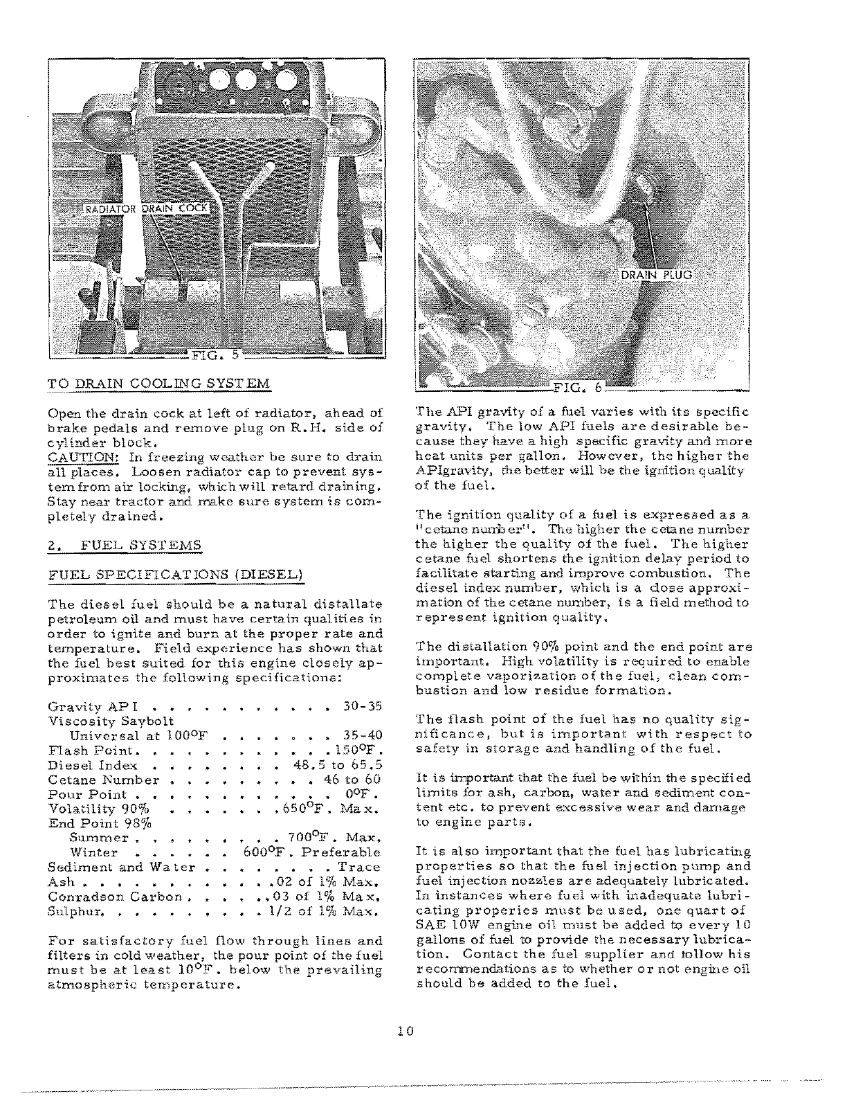
TO
DRAIN
COOLING
SYSTEM
Open
the
drain
cock
at
left
of
radiator,
ahead
of
brake
pedals
and
remove
plug
on
R~
H.
side
of
cylinder
block.
CAUTION:
In
freezing
weather
be
sure
to
drain
all
places~
Loosen
radiator
cap
to
prevent
sys-
temfrorn
air
locking.
which
will
retard
draining.
Stay
near
tractor
and
make
sure
system
is
com-
pletely
drained.
2.
FUEL
SYSTEMS
FUEL
SPECIFICATIONS
(DIESEL)
The
diesel
fuel
should
be
a
natural
distallate
petroleun1
oil
and
must
have
certain
qual
tties
in
order
to
ignite
and
burn
at
the
proper
rate
and
temperature.
Field
experience
has
shown
that
the
fuel
best
suited
for
this
engine
closely
ap-
proxi.mates
the
following
specifications:
Gravity AP
I
Viscosity
Saybolt
Uni.versal
at
lOooF
Flash
Point.
Diesel lndax
ectane
Number
Pour
Point
.. .,
Volatility
900/,
End
Point
98%
Summer
~
Winter
Sediment
and
Wa
tel'
Ash.
Conradson
Carbon.
Sulphur.
30-35
35-40
•
150
0
F.
48.5
to
65.5
• •
46
to
60
• • • •
OOF
•
.
650°F.
Max.
• •
700°F.
Max.
600°F.
Pr
e£erab1e
•
Trace
•
.02
of
1%
Max.
..03
of
1%
Max.
•
1/2
of
1%
Max.
For
satisfactory
fuel
flow
through
lines
and
filters
in
cold
weather,
the
pour
point
of
the
fuel
must
be
at
least
10°F.
below
the
prevailing
atmospheric
temperature.
10
The
API
gravity
of
a
fuel
varies
with
its
specific
gravity.
The
low
API
fuels
are
desirable
be-
cause
they
have
a
high
specific
gravity
and
more
heat
units
per
gallon.
However,
the
highet"
the
APIgraY;'ty,
t:he
better
will
be
the
ignition
quality
of
the
fuel.
The
ignition
quality
of
a
fuel
is
expressed
as
a
11cetane
nurrb
er
".
The
higher
the
ectane
number
the
higher
the
quality
of
the
fuel.
The
higher
c
etane
fuel
shortens
the
ignition
delay
period
to
facilitate
starting
and
improve
combustion.
The
diesel
index
number,
which
is
a
dose
approxi-
mation
of
the
ectane
number~
is
a
field
method
to
r
epres
ent
ignition
quality.
The
distallation
90%
point
and
the
end
point
are
lrnportant.
High
volatility
is
required
to
enable
complete
vaporization
of
the
fuel,
clean
com-
bustion
and
low
residue
formation.
The
flash
point
of
the
fuel
has
no
quality
sig-
nificance,
but
is
important
with
respect
to
safety
in
storage
and
handling
of
the
fuel
•
It
is
wportant
that
the
fuel
be
within
the
specified
linlits
for
ash)
carbon.
water
and
sediment
con-
tent
etc.
to
prevent
excessive
wear
and
danlage
to
engine
parts.
It
is
also
important
that
the
fuel
has
lubricating
properties
so
that
the
fuel
injection
pump
and
fuel
injection
nozz"!..es
are
adequately
lubricated~
In
instances
where
fu
e1
with
inadequate
lubri-
eating
properies
must
be
u
sed,
one
quart
of
SAE
lOW
engine
oil
must
be
added
to
every
10
gallons
of
fuel
to
provide
the
necessary
lubrica-
tion.
Contact
the
fuel
supplier
and
follow
his
recommendations
as
to
whether
or
not
engitlc
oil
should
be
added
to
the
fuel.
CAUTION:
The
sulphur
content
of
diesel
fuel
should
be
as
low
as
possible.
The
fuel
should
not
contain
a
sulphur
content
of
more
than
1/2
of
1%.
Generally
speakingJ
a
No.2
high
speed
diesel
fuel
purchased
froIT' a
reputable
oil
company
wilirr:eet
the
above
specifications.
FUEL
SPE
CIFICAT
IONS
(GASOLINE)
This
engine
is
designed
to
burn
regular
gasoline
having
an
octane
rating
(research
method)
of
89
or
higher.
Fuel
cornpanies
provide
fuels
tailored
to
f'reet
the
existing
weather
conditions.
These
fuels
are
changed
at
the
start
of
the
predorninent
seasons
according
to
regional
weather
trends.
Fuels
are
tailored
to
give
ease
of
starting
in
cold
weather
and
to
give
a
low
vapor
pressure
to
avoid
vapor
lock.
An
effort
should
be
made
to
purchase
fuels
in
such
quantity
that
they
are
not
carried
over
to
succeeding
seasOns.
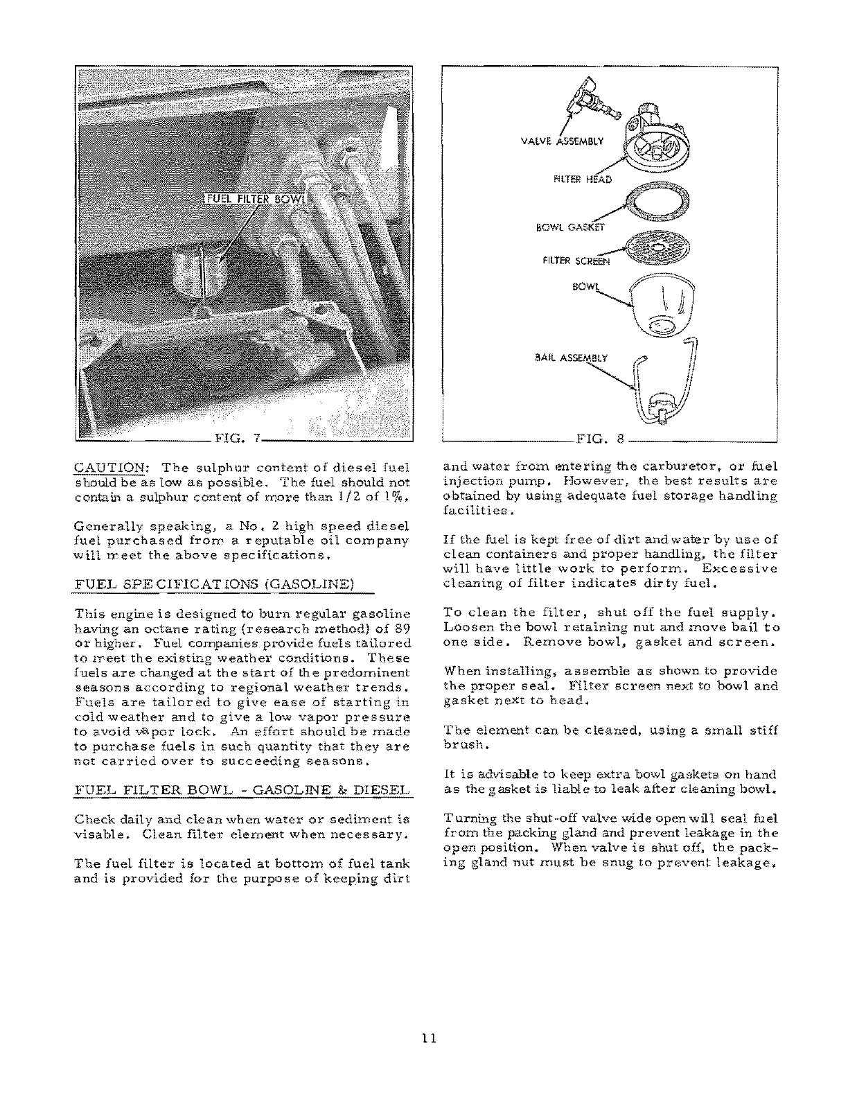
FUEL
FILTER
BOWL
-
GASOLINE
&
DIESEL
Check
daily
and
clean
when
water
or
sediment
is
visable.
Clean
filter
element
when
necessary.
The
fuel
filter
is
located
at
bottom
of
fuel
tank
and
is
provided
for
the
purpose
of
keeping
dirt
11
A~,
JJ~~
VALVE
ASSEMBLY
~.
'
FILTERH::O
BOWL
GASKET
FILTER
BOWl
f'I~
~
\\&1
\©J
BAIL
ASSEMBLY
r?
!l
""
[\
1/
~
'--
______
FIG.
8
_______
..J
and
water
from
entering
the
carburetor,t
or
fuel
injection
pump.
However,
the
best
results
are
obtained
by
using
adequate
fuel
storage
handling
facilities.
If
the
fuel
is
kept
free
of
dirt
and
water
by
use
of
clean
containers
and
proper
handling,
the
filter
will
have
little
work
to
perform.
Excessive
cleaning
of
filter
indicates
dirty
fuel.
To
clean
the
filter,
shut
off
the
fuel
supply.
Loosen
the
bowl
retaining
nut
and
!nove
bail
to
one
side.
Remove
bowl,
gasket
and
screen~
When
installing,
a
ssemble
as
shown
to
provide
the
proper
seal.
Filter
screen
next
to
bowl
and
gasket
next
to
head.
The
element
can
be
cleaned,
using
a
small
stiff
brush.
It
is
advisable
to
keep
extra
bowl
gaskets
on
hand
as
the
gasket
is
liable
to
leak
after
cleaning
bowl.
Turning
the
shut-off
valve
wide
open
will
seal
fuel
from
the
packing
gland
and
prevent
leakage
in
the
open
positi.on~
When
valve
is
shut
off,
the
pack-
ing
gland
nut
Inust
be
snug
to
prevent
leakage.

FUEL
FILTER
(HD-4
DIESEL)
The
fuel
system
is
provided
with
a
primary
and
secondary
fuel
filter
nlounted
in
one
element
on
the
side
of
the
engine.
The
purpose
of
the
fuel
filter
is
to
renlovewater.
sediment
f$
abrasives
from
the
fuel,
before
the
fuel
enters
the
injection
equipment.
The
proper
handling
and
storage
of
fuels
will
increase
the
life
On
the
filters.
Replace
the
filter
element
at
each
500
hours
of
operation.
Poor
fuel
handling
and
storage
facil-
ities
will
decrease
the
effective
life
of
the
filter.
In
other
words,
dirty
fuel
will
decrease
the
life
of
a
filter.
while
clean
fuel
will
increase
the
life
of
a
filter.
Never
operate
until
filter
becomes
plugged,
or
to
a
point
to
where
a
decrease
in
engine
speed
Or
power
is
noticed.
SODle
dirt
may
seE'k
its
way
through
the
secondary
filter
and
cause
severe
damage
to
the
fuel
injection
equip-
ment.
Each
time
the
filter
element
is
removed,
it
may
be
necessary
to
bleed
out
air
by
remov1t:..g
the
plug
at
top
of
filter
head
assembly.
Remove
air
bleed
plug
and
turn
On
fuel
valve
at
tank.
Operate
the
hand
priming
pump
until
all
air
has
escaped
and
solid
fuel
is
to
the
level
of
the
air
bleed
plug
and
install
bleed
plug
at
top
of
filter
head.
FeEL
STORAGE
The
importance
of
proper
storage
of
fuel
cannot
be
too
strongly
stressed.
Storage
tanks,
drums,
or
service
tanks
must
be
free
of
rust,
scale,
sediment,
or
any
other
foreig:c.
matter
which
will
contaminate
the
fuel.
Contaminated
fuel
will
clog
the
engine
fuel
filters
and
eventually
damage
the
fuelilljection
puIl1'
and
the
fuel
injection
nozzles.
A
portable
storage
tank
provides
the
best
method
for
storing
fuel
on
the
jo
b.
In
such
a
tank,
the
sediment
and
water
can
easily
be
drained
and
the
fuel
can
be
pumped
into
the
tractor
fuel
tank
with
a
minimum
of
handling.
Since
condensation
will
occur
in
the
storage
tank"
it
is
very
important
that
a
sediment
sump
be
pro'vided
i1':.
botton)
of
tank
so
that
water
and
sediment
can
be
drai:!1ed
daily.
Fuel
should
be
allowed
to
settle
at
least
48
hours
i.n a
storage
container
before
being
added
to
the
fuel
tank
of
the
tractor,
It
is
advisable
to
use
a
pun1p
and
draw
the
fuel
frorn
storage
tank,
or
barrel,
rather
than
to
drain
it
from
bottom
of
fuel
container.
Vihere
conditions
are
such
that
drums
must
be
used
to
supply
fuel,
it
is
advisable
to
have
enough
drums
to
allow
sufficient
time
for
the
fuel
to
settle~
The
fuel
thus
left
in
a
number
of
drums
CaZ'l
be
collected
into
one
drum
and
used
after
the
usual
time
allowed
for
settling.
L"1
this
manner,
the
sediment
and
fo
reign
matter
will
be
disposed
of
and
no
fuel
will
be
wasted.
Whenever
drums
are
used
for
fuel
storage,
they
should
be
covered
Or
placed
under
shelter
so
that
the
fuel
will
not
becon1e
contaminated
by
water
I
which
will
enter
through
the
filler
plugs
when
it
rains,
even
though
plugs
are
ti.ght.
The
fuel
tank
of
the
tractor
should
be
filled
at
end
of
the
day's
run
rather
than
at
the
start;
this
will
reduce
the
water
content
J
as
a
full
tank
is
less
subject
to
cor.densati.on.
3.
ENGINE
LUBRICATING
SYSTEM
A.
ENGINE
CRANKCASE
(Lubricant
Specifica-
tion)
(Diesel)
The
specified
oil
for
use
in
the
engine
crankcase
is
a
lubricating
on
that
meets
both
of
the
follow-
ing
specifications:
1.
American
PctrolclUn
Institute
(API)
classi-
fication
nService
DS
Series
3
11
2.
Military
Specifications
"MIL-L-4S199A"
NOTE:
The
engine
crankcase
on
a
new
unit
when
shipped
from
the
factory,
contains
1lS
er
i.es
3!!
SAE
20W
engine
lubri.cating
oil
meeting
the
proper
API
Military
Specifications.
This
oil
is
completely
satisfactory
for
use
until
the
first
regular
oil
change.
B.
ENGINE
CRAA"KCASE
(Lubricant
Specifica-
tions)
(Gasoline)
Motor
oils
are
designated
by
code
letters
as
iollows:
ML
-
MM
-
MS.
The
letters
denote
the
type
of
service
for
which
the
unit
is
used.
ML
-
for
use
under
light
loads
and
favorable
conditions.
12
This manual suits for next models
1
Table of contents
Other Allis-Chalmers Tractor manuals

Allis-Chalmers
Allis-Chalmers 910-6 Speed User manual

Allis-Chalmers
Allis-Chalmers G User manual

Allis-Chalmers
Allis-Chalmers B Install guide

Allis-Chalmers
Allis-Chalmers ac130 series User manual

Allis-Chalmers
Allis-Chalmers U Installation and user guide

Allis-Chalmers
Allis-Chalmers 10 hp User manual

Allis-Chalmers
Allis-Chalmers regent hydro 14 User manual

Allis-Chalmers
Allis-Chalmers HD-9 User manual

Allis-Chalmers
Allis-Chalmers WD Use and care manual

Allis-Chalmers
Allis-Chalmers G User manual


