Allis-Chalmers HD-14 User manual

INSTRUCTION BOOK
FOR ·
MODiEL
HD 14 TRACTOR
ALLIS-CMALMERS MFG. CO.
i1'RACTOR DIVISION
LITHO. IN U. S. A.
FORM T-200 B
MILWAUKEE, WISCONSIN, U.S.A.
•
I N D E X
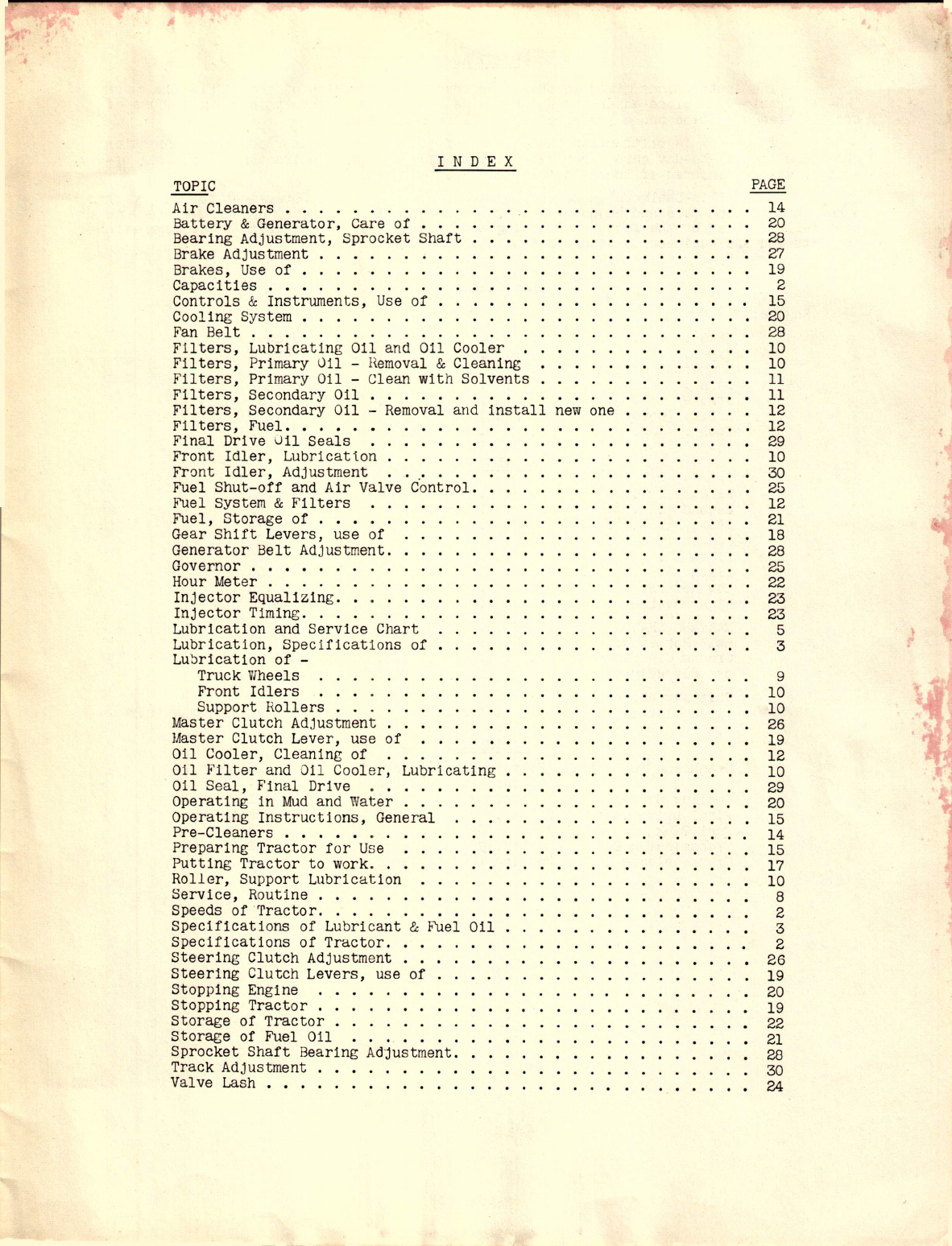
Air Cleaners . . . . . . . .
Battery
&
Generator, Care of
Bearing Adjustment, Sprocket Shaft
Brake Adjustment • . .
Brakes, Use of •......
Capacities •••......
Controls
&
Instruments, Use of
Cooling System . . .
Fan Belt ••.•.......
Filters, Lubricating Oil and Oil Cooler
F'IIters, Primary Oil - Hemoval
&
Cleaning
Filters, Primary Oil - Clean with Solvents
Filters, Secondary Oil ....
Filters, Secondary Oil - Removal and install new one
Filters, Fuel .•.•.
Final Drive Uil Seals
Front Idler, Lubricatlon
Front Idler, Adjustment .
Fuel Shut-off and Air Valve Control.
Fuel System
&
Filters
Fuel, Storage of .•••.
Gear Shift Levers, use of
Generator Belt Adjustment.
Governor . . • • . .
Hour Meter . . . . .
Injector Equalizing.
Injector Timing ...
Lubrication and Service Chart
Lubrication, Specifications of
Lu~rication of -
Truck Wheels
Front Idlers
Support Rollers
Master Clutch Adjustment
Master Clutch Lever, use of
Oil Cooler, Cleaning of
Oil Filter and Oil Cooler, Lubricating
Oil Seal, Final Drive .....
Operating in Mud and Water . . .
Operating Instructions, General
Pre-Cleaners . • • • • . .
Preparing Tractor for Use
Putting Tractor to work. .
Roller, Support Lubrication
Service, Routine .
Speeds of ·Tractor .
Specifications of Lubricant
&
Fuel Oil
Specifications of Tractor .•.
Steering Clutch Adjustment . .
Steering Clutch Levers, use of
Stopping Engine
Stopping Tractor . . . . . . .
Storage of Tractor . . . . . .
Storage of Fuel Oil .. " .
Sprocket Shaft Bearing Adjustment.
Track Adjustment "
Valve Lash •.........•.
.'
PAGE
14
20
28
27
19
2
15
20
28
10
10
11
11
12
12
29
10
30
25
12
21
18
28
25
22
23
23
5
3
TOPIC
9
10
10
26
19
12
10
29
20
15
14
15
17
10
8
2
3
2
26
19
20
19
22
21
28
30
24
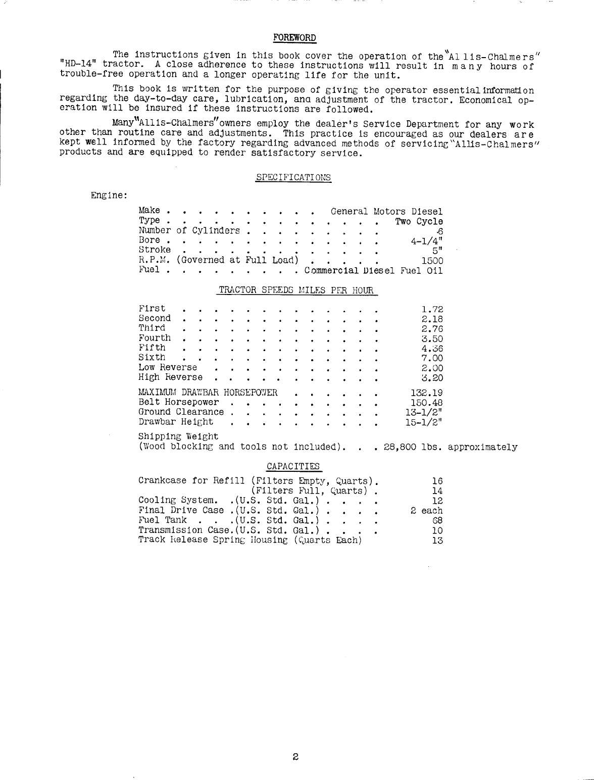
FOREWORD
~ II
The instructions given in this book cover the operation of the Allis-Chalmers
"HD-14" tractor. A close adherence to these instructions will result in man y hours of
trouble-free operation and a longer operating life for the unit.
This book is written for the purpose of giving
t
he
operator essentialinformation
regarding the day-to-day care, lubrication, ana adjustment of the tractor. Economical op-
eration will be insured if these instructions are followed.
Many"Allis-Chalmers"owners employ the dealer's Service Department for any work
other than routine care and adjustments. This practice is encouraged as our dealers are
kept well informed by the factory regarding advanced methods of servicinc"Allis-Chalmers"
products and are equipped to render satisfactory service.
SPECIFICATIONS
Engine: Make •
Type •
Number of Cylinders
Bore •
st.rojce
R.P.M.
FuaL • ...
.
.
...
(Governed at Full Load)
General Motors Diesel
Two Cycle
·6
4-1/4"
5"
1500
Commercial D1esel Fuel Oil
TRACTOR SPEEDS MILF:SPER HOUR
First
Second
'l'hird
Fourth
Fifth
Sixth
Low Reverse
High Reverse
MAXIMUM
DRAWBAR HORSEP07JER
Belt Horsepower
Ground Clearance
Drawbar He
Ight
Shipping VJeight
(Wood blocking and tools not included).
1.72
2.18
2.76
3.50
4.06
7.00
2.00
3.20
132.19
150.48
13-1/2"
15-1/2"
• 28,800 Ibs. approximately
CAPACITIES
Crankcase for Refill (Filters Empty, Quarts).
(Filters Bull, Quarts)
Cooling System. .(U.S. Std. Gal.) .
Final Drive Case
.(U.S.
Std. Qal.) •
Fuel Tank • . .(U.S. Std. Gal.) •
Transmission Case.(U.S. Std. Gal.). •
Track
lee
Lease Sprint::
Hous
inc (,~uartsEach)
16
14
12
2 each
68
10
13
2

SPECIFICATIONS OF LUBRICANTS AND FUEL OIL
ENGINE CRANKCASE LUBRICANT:
USE NON-CORROSIVE DIESEL ENGINE LUBRICATING OIL CONTAINING ADDITIVES
PREVENTING SLUDGE OR GUM DEPOSITS.
ATMOSPHERIC TEMP. VISCOSITY
Abgve 900 Fo Use SAE. 30
32oF. to 900F. Use SAE. 30
10 F. to 32 F. Use SAE. 20
Below 100F. Use SAE. 10
WARNING: The main, connecting rod and idler gear bearings of this
engine are lead bronzed lined. UNDER NO CIRCUMSTANCES
SHOULD A CORROSIVE DIESEL ENGINE LUBRICATING OIL EVER
BE USED.
All manufacturers of lubricants have recognized the importance of the quaIl ties
required for use in our equipment and they are now co-operating fully to insure the use of
~nly those oils which fulfill these requlrements. The 011 distributor
and
011 manufacturer
are to be held responsible for the results obtained from their products.
TRANSMISSION. FINAL DRIVE. TRUCK WHEEL. FRONT IDLER AND TRACK SUPPORT ROUER
LUBRICANT.
Use a motor oil recommended by Allls-Chalmers Mfg. Company. See nearest Allis-
Chalmers factory branch or authorlzed"Allis-Chalmers"dealer for approved list. Copy of
approved l1st is shipped with each tractor.
ATMOSPHERIC TEMP·
ABove 320F
O
o
F.
to 32
F.
Below OOF.
VISCOSITY
Use SAE. 40 or 50
Use SAE. 20 or 30
Use SAE. 10
PRESSURE GUN FITTINGS
Use a pressure gun lubricant with a minimum melt1ng po1nt
of
3000F. This lubri-
cant should be in a viscosity range so as to insure easy handling in the pressure gun at
prevailing air temperatures.
~ In selecting the pressure gun lubricant make certain that it will not
wash away in presence of water.
FUEL OIL
1. Purchase from a reputable oil company a fuel within the 11m1ts
of No.1 or No.2 Diesel Fuel Oil according to the American
Society of Testing Materials. Some No. 3 fuel ol1s can be used.
2. The cetane number should be at least 40, since this quality 1s
a measure of smoothness of combustion and ease of starting.
3. The fuel oil should be free enough from high boiling fractions
to give clean combustion.
4. The pour point should be low enough to permit it to flow freely
under the required operating conditions.
5. The fuel oil must be free from alkali, mineral aCid,
gum,
free
sulphur, sediment and fibrous or other foreign matter.
3
I
o
I
A

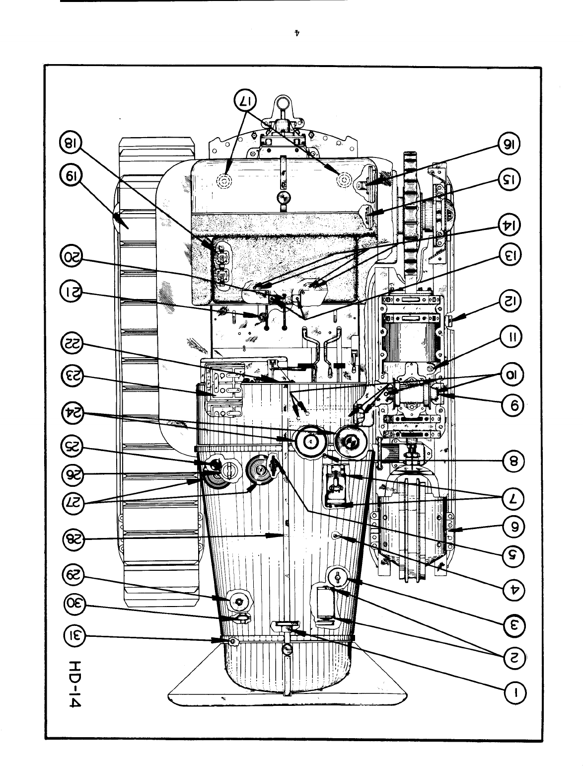
"HD 14" LUBRICATION AND SERVICE CHART
1.
FAN - One lubrication point. Lubricate 17.
every 200 hours of operation with pres-
sure gun lubricant.
GENERATOR - Two lubrication pOints. Lu-
bricate every 200 hours of operation
with light motor oil. 18.
2.
3.
SECONDARY OIL FILTER - Install
element in the secondary filter
240 hours of operation or every
oil change. Refer to Topic 10.
a new
every
fourth 19.
20.
4.
CRANKCASE 13AYONNET GAUGE - Inspect oil
level every 10 hours of operation.
THROTTLE LEVER DISC - Lubricate when
necessary for easy operation with pres-
sure gun lubricant; do not over-lubricate.
FRONT IDLER - Two lubrication pOints.
Lubricate every 200 hours of operation
with
18
strokes of the gun. Use approved
motor oil. Refer to Topic 7.
STARTER - Two lubrication points. Lu-
brica te every 200 hours of opera tion
with light motor oil.
CLUTCH SHIFTI<.:RBEAlUNG -Lubricate every
10 hours of operation with pressure
gun
lubricant of high heat resistance.
TRACK SUPPORT ROLLER - Two lubrication
points. Lubricate every 200 hours of
operation with 10 strokes of the gun.
Use approved motor oil. Hefer to Topic
8.
STABILIZER CEANK ASSEMBLY - Twelve lu-
brication points. Lubricate every 10
hours of operation with pressure gun lu-
bricant.
TRACK RELEhSE SPEING MECHANISM--Inspect
011
level every 200 hours of operation.
Keep filled to filler plug with motor
oil same viscosity as used in trans-
mission. Drain, flush and refill with
motor oil same viscosity as used in
transmission every BOO hours of opera-
tion. Capacity 13 quarts.
TEUCK WHEELS--Ten lubrication points.
Lubricate every 200 hours of operation
with B-l/2 strokes of the gun. Use ap-
proved motor oil. Refer to Topic 6.
BELL CRANK THHUST PIN - Two lubrication
points. Lubricate every 10 hours of op-
eration with pressure gun lubricant.
STEEEING CLUTCH THROVlOUT BEAEING - Four
lubrication pOints. Lubricate every 10
hours of operation with pressure gun
lubricant of high heat resistance.
FINAL DHIVE DRAIN PLUG - Drain flush,
and refill every ;~OOto 400 hours of op-
eration. Capacity B quarts each.
FINAL DElVE FILLE.:ll,.PLUG -- Inspect oil
level every 10 hours of operation. Keep
filled to level of filler elbow with
approved motor oil.
5.
6.
7.
B.
9.
10.
11.
12.
13.
14.
15.
16.
5
21.
SEDIMENT TRAPS - Drain traps every mor-
ning before starting, or more often if
necessary. In freezing weather, drain
after stopping so water will not freeze
in traps.
FIRST STAGE FUEL OIL FILTERS - Install
new elements when necessary. Eefer to
Topic
11.
TRACKS - No lubrication necessary.
TRANSHISSION DRAIN PLUG - Drain, flush,
and refill every BOO hours of operation
with approved motor oil. Capacity 40
quarts.
TRANSMISSION CASE FILliE PLUG AND OIL
LEVEL BAYONNET GAUGE -Inspect
011
level
every' 10 hours of operation and keep the
oil level between "Low" and "Full" on
the bayonet gauge.
LUBEICATING OIL PRESSUEE GAUGE - Normal
operating pressure when engine is warm
at 'full throttle is 25 to 35 on the
gauge; if gauge does not register stop
engine immediately and determine the
cause.
BATTERIES - Keep the top and terminals
clean. Keep filled with clean distilled
water to 3/B" above separator plates;
inspect water level daily. Test with a
hydrometer.
AlE CLEANEf-S - Inspect and service every
10 hours of operation. Refer to Topic
13.
CRANKCASE FILLER CAP - One filler point.
Change oil every 30 to 60 hours of
operation. USE NON-CORROSIVE DIESEL
LUBRICATING OILS CONTAINING ADDITIVES
PHEVENTING SLUDGE OR GUM DEPOSITS. Cap-
acity 14 quarts.
SECOND STAGE FUEL OIL FILTEE - Install
new element when necessary, that is,
when pressure drops below normal range
(25 to 65) due to filter clogging. Re-
fer to Topic
11.
PRE-CLEANERS - Inspect and service ev-
ery 10 hours of operation. Refer to
Topic 12.
CRANKCASE DRAIN PLUG - One drain point.
Drain and refill with new oil every 30
to 60 hours of operation. Eefer to Topic
lAo
PRIMAEY OIL FlITER - Clean the Primary
Oil Filter at each crankcase oil change.
Eefer to Topic 10.
WATER PU},!PDEAIN - Periodically drain
and flush out system. Refer to Topic 18.
RADIATOR DRAIN - Periodically drain and
flush out system. Eefer to Topic lB.
Capacity 12 gallons.
22.
23.
24.
25.
26.
27.
28.
29.
30.
31.

6

7
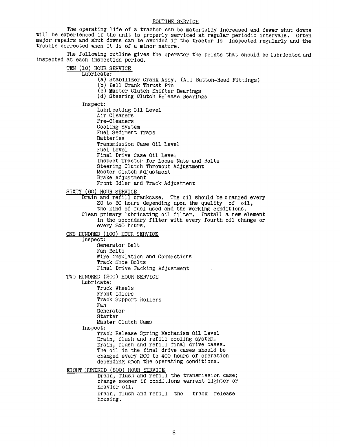
ROUTINE SERVICE
The operating life of a tractor can be materially increased and fewer shut downs
will be experienced if the unit is properly serviced at regular periodic intervals. Often
major repairs and shut downs can
be
avoided
if
the tractor is inspected regularly and the
trouble corrected when it is of a minor nature.
The following outline gives the operator the pOints that should be lubricated and
inspected at each inspection period.
TEN (10) HOUR SERVICE
Lubricate:
(a) Stabilizer Crank Assy. (All Button-Head Fittings)
(b) 8ell Crank Thrust Pin
(c) Master Clutch Shifter Bearings
(d) Steering Clutch Release Bearings
Inspect:
Lubrlcating 011 Level
Air Cleaners
Pre-Cleaners
Cooling System
Fuel Sediment Traps
Batteries
Transmission Case Oil Level
Fuel Level
Final Drive Case Oil Level
Inspect Tractor for Loose Nuts and Bolts
Steering Clutch Throwout Adjustment
Master Clutch Adjustment
Brake Adjustment
Front Idler and Track Adjustment
SIXTY (60) HOUR SERVICE
Drain and refill crankcase. The oil should be changed every
30 to 60 hours depending upon the quality of Oil,
the kind of fuel used and the working conditions.
Clean primary lubricating oil filter. Install a new element
in the secondary filter with every fourth oil change or
every 240 hours.
ONE HUNDRED (100) HOUR SERVICE
Inspect:
Generator Belt
Fan Belts
Wire insulation and Connections
Track Shoe Bolts
Final Drive Packing Adjustment
~NO
HUNDRED (200) HOUR SERVICE
Lubricate:
Truck Wheels
Front Idlers
Track Support Rollers
Fan
Generator
Starter
Master Clutch Cams
Inspect:
Track Release Spring Mechanism Oil Level
Drain, flush and refill cooling system.
Drain, flush and refill final drive cases.
The oil in the final drive cases should be
changed every 200 to 400 hours of operation
depending upon the operating conditions.
EIGHT HUNDRED (800) HOUR SERVICE
Drain, flush and refill the transmission case;
change sooner if conditions warrant lighter or
heavier oil.
Drain, flush and refill the
housing, track release
8
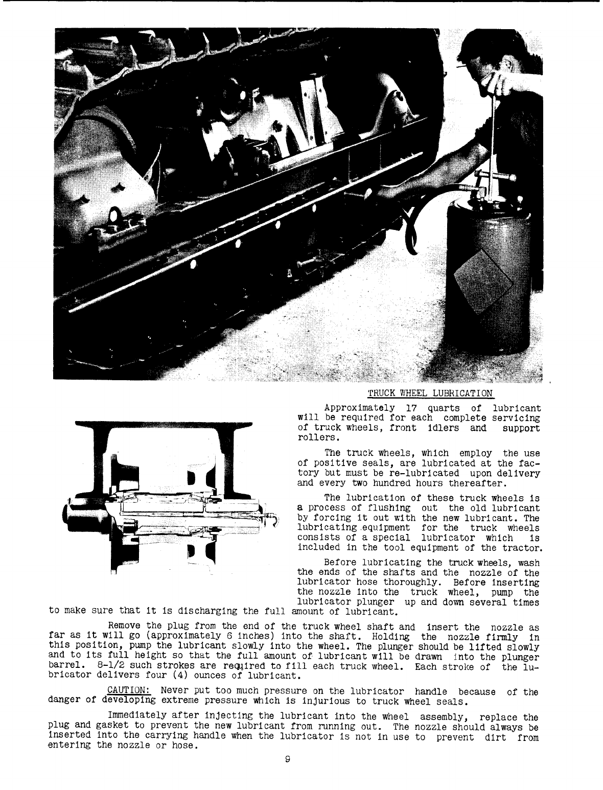
TRUCK WHEEL LUBRICATION
Approximately 17 quarts of
will be required for each complete
of truck wheels, front idlers and
rollers.
The truck wheels, which employ the use
of positive seals, are lubricated at the fac-
tory but must be re-lubricated upon delivery
and every two hundred hours thereafter.
The lubrication of these truck wheels is
a process of flushing out the old lubricant
by forcing it out with the new lubricant. The
lubricating.equipment for the truck wheels
consists of a special lubricator which is
included in the tool equipment of the tractor.
lubricant
servicing
support
Before lubricating the truck wheels, wash
the ends of the shafts and the nozzle of the
lubricator hose thoroughly. Before inserting
the nozzle into the truck wheel, pump the
lubricator plunger up and down several times
to make sure that it is discharging the full amount of lubricant.
Remove the plug from the end of the truck wheel shaft and insert the nozzle as
far as it will go (approximately 6 inches) into the shaft. Holding the nozzle firmly in
this position, pump the lubricant slowly into the wheel. The plunger should be lifted slowly
and to its full height so that the full amount of lubricant will be drawn into the plunger
barrel. 8-1/2 such strokes are reQ,!ired to f111 each truck wheel. Each stroke of the lu-
bricator delivers four (4) ounces of lubricant.
CAUTION: Never put too much pressure on the lubricator handle because of the
danger of developing extreme pressure which is injurious to truck wheel seals.
Immediately after injecting the lubricant into the wheel assembly, replace the
plug and gasket to prevent the new lubricant from running out. The nozzle should always be
inserted into the carrying handle when the lubricator is not in use to prevent dirt from
entering the nozzle or hose.
9
TRUCK WHEEL LUBRICATION (Cont'd.)
Use only motor oil recorrmended by Allis-Chalmers--see the nearest Allis-Chalmers
dealer or Allis-Chalmers factory branch for the current approved list of oils.
FRONT IDLER LUBRICATION
The front idlers are lubricated with the same equipment and in the same manner
with the same 011 as the truck wheels. Each front idler should
be
serviced with 18 strokes
of the lubricator.
SUPPORT ROLLER LUBRICATION
The track support rollers are lubricated with the same equipment and in the same
manner as the truck wheels and front idlers. Each support roller should be serviced with
10
strokes of the lubricator•
...I
HOUSINGI
~
ELEMENT
RETAINER BOLT
GASKET
WASHER
LEMENT
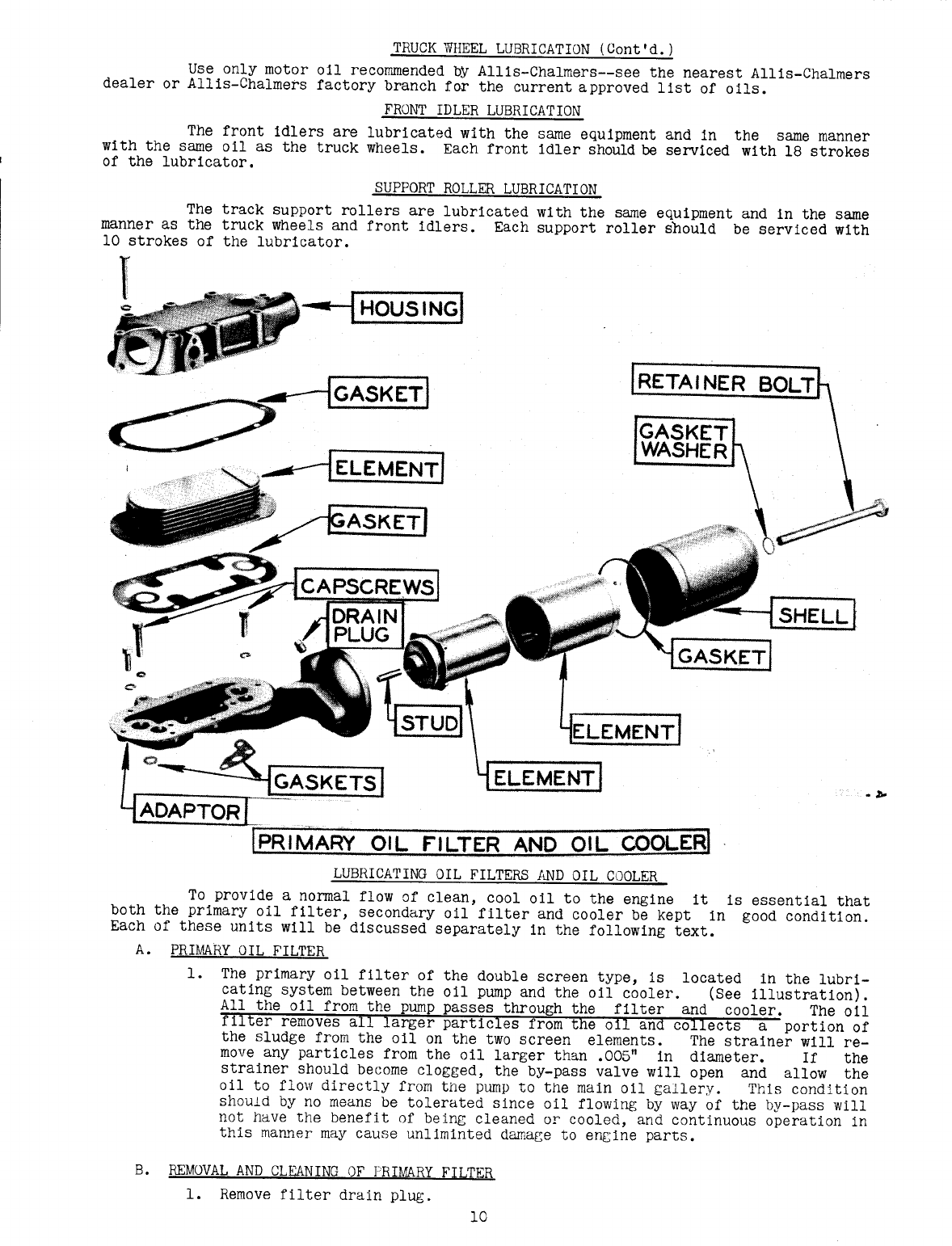
LUBRICATING OIL FILTERS AND OIL COOLER
To provide a normal flow of clean, cool oil to the engine it is essential that
both the primary oil filter, secondary oil filter and cooler be kept in good condition.
Each of these units will be discussed separately in the following text.
A. PRIMARY OIL FILTER
1.
The primary oil filter of the double screen type, is located in the lubri-
cating system between the oil pump and the oil cooler. (See illustration).
All the oil from the pump passes through the filter and cooler. The oil
filter removes all larger particles from the
011
and collects a portion of
the sludge from the oil on the two screen elements. The strainer will re-
move any particles from the 011 larger than
.005"
in diameter. If the
strainer should become clogged, the by-pass valve will open and allow the
all to flow directly from the pump to the main 011 gallery. This condition
ShOUld
by no means be tolerated since all flowing by way of the by-pass will
not have the benefit of being cleaned or cooled, and continuous operation in
this manner may cause unliminted damage to engine parts.
B. REMOVAL AND CLEANING OF PRIMARY FILTER
1.
Remove filter drain plug.
10
LUBRICATING OIL FILTERS AND OIL COOLER (Cont'd.)
2. Remove the oil filter retainer bolt.
3. Remove the oil filter shell and filter elements from the filter base.
4. The f11ter elements must be washed after every 011 change. Wash the elements
in fuel oil with a soft brush. Do not scrape the elements with a sharp or
metal Instrument or wash them with a wire brush. Wash the filter base and
outer shell before reassemblIng.
After washing, reassembly the filter on the filter base. After assembling
check to see whether copper gasket under retaIner bolt prevents oil leaks.
Also be sure oil filter shell gasket fits properly. Run the motor for a few
minutes and inspect for oil leaks.
C. CLEANING PRIMARY FILTER ELEMENTS AND OIL COOLER WITH SOLVENTS.
A filter element that has become loaded with impurities due to neglect can
usually be cleaned only through use of special solvents in conjunction with
some type of circulating system that will create a flushing action.
NOTE: When a filter element Is removed from an engine it should be cleaned
immediately. Do not allow a dirty element to dry, since this will cause lac-
quer or sludge deposits to harden. Keep submerged in a pail of fuel oil be-
fore cleaning.
1.
Effective solvents
Excello Floor cleaning compound
Bendix cleaning compound
Turco cleaning compound
#70
stripper
A mixture of Qaklte
#7
and fuel oil. 3 parts Oakite and 5 parts of fuel oil.
NOTE: The solvents listed above should be
used according to the directions of manufac-
ture. After cleaning operation Is completed
all traces of the cleaning solution should
be washed from the filter elements. In the
event that the above procedure does not
eliminate the clogged condltion, a new fllter
element must be installed.
2. Another very effective solvent Is
the new BendIx cleaner which dissolves or
loosens the sludge or other foreign matter
that may be collected on the metal of the
oil cooler or filter elements.
Its applIcatIon is very simple since all
that is required is submersion of cooler or
filter in solution for a sufficient length
of time to allow the chemical action of the
fluid to properly remove the impurities. The
length of time for the submersion will de~
upon the condition of the cooler or filter
elements.
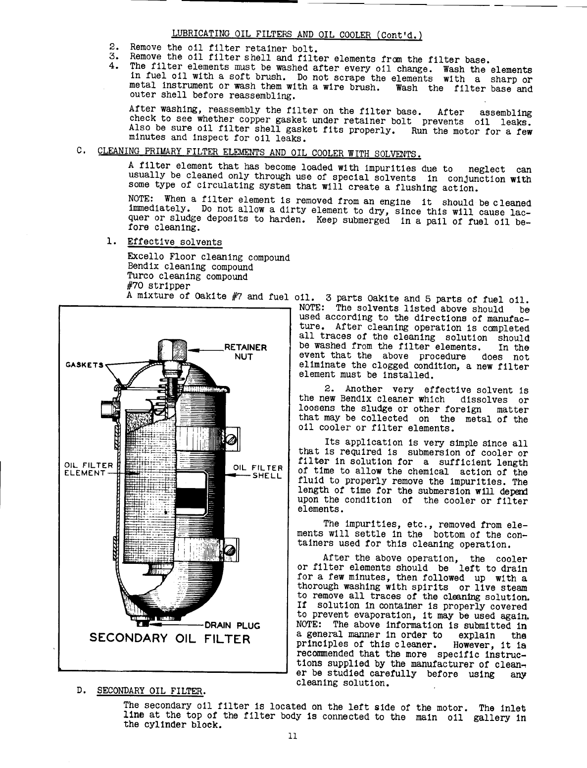
PLUG
SECONDARY OIL FILTER
FIL TER
SHELL
The impurities, etc., removed from ele-
ments will settle in the bottom of the con-
tainers used for this cleaning operation.
After the above operation, the cooler
or filter elements should be left to drain
for a few minutes, then followed up with a
thorough washing with spirits or live steam
to remove all traces of the cleaningsolution.
If solution In containerIs properly covered
to prevent evaporatlon, it may be used again.
NOTE: The above informatlon Is submitted in
a general manner in order to explaln the
principles of this cleaner. However, it is
recommended that the more specific instruc-
tions supplied by the manufacturer of clean~
er be studied carefully before using any
cleaning solution.
D. SECONDARY OIL FILTER.
The secondary oil filter is located on the left side of the motor. The inlet
line at the top of the filter body is connected to the main oil gallery 1n
the cylinder block.
11
LUBRICATING OIL FILTERS AND OIL COOLER (Cont'd.)
The outlet line from the filter body is at the bottom and drains back into
the crankcase.
Only a portion of the oil flows through this filter. This filter has a re-
placeable element and must be changed every 4th oil change or every 240 hours
of operation.
E.
REMOVAL OF SECONDARY FILTER ELEMENT AND INSTALLATION OF A NEW ONE.
1. Remove the drain plug at the bottom of body and loesen the cever. Let the .oil
drain .outbefore removing the element.
2. Remeve the filter element and discard it.
3. Clean out the filter body and replace drain plug.
4. Install new element, new cover gasket and tighten cever securely.
5. When installing new element one extra quart of oil is required for crankcase
f11l1ng. NOTE: When filling crankcase with 011 fill only to full mark on
crankcase bayonet gauge.
6. Start motor, inspect for leaks and run for a few minutes. Then step motor and
let it set long enough for the oil to drain back inte crankcase. Check crank-
case bayonet gauge te see if more .oilis needed.
7. In cold weather the motor should be run long enough to attain operating temp-
erature before checking the oil level.
F. OIL COOLER
1.
The lubricating 011 cooler lowers the oil temperature as the 011 travelS
through the small passages inside the cooling element. If these passages
become entirely clogged, no cooling of the oil can take place, and the oil is
by-passed without filtering or cooling directly to cylinder block oil galler~
It is absolutely necessary that the oil cooler element be kept clean for pro-
per oil cooling.
2. Cleaning of a clogged cooler is sometimes very difficult. A cooler that has
become loaded with impurities over a long period of operation can usually be
cleaned only through use of special solvents in conjunction with some type of
circulating system that will create a flushing action. However, in most cases
the use of any of the special solvents, as listed perviously, in a hand oper-
ated force pump will dislodge any accumulation. In the event that such treat-
ment does not eliminate the clogged condition, a new cooler element must be
installed.
NOTE: A clogged 011 cooler or filter is a contributing factor in low engine
oil pressure which may be the cause of one or many operating difficulties.
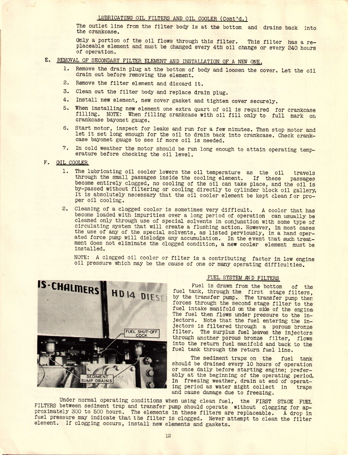
FUEL SYSTEM
.AN
D FILTERS
Fuel is drawn from the bottom of the
fuel tank, through the first stage filters,
by the transfer pump. The transfer pump ther.
forces through the second stage filter to the
fuel intake manifold on the sideof the engine
The fuel tnen flows under pressure to the in-
jectors. Note that the fuel entering the in-
jectors is filtered through a por.ousbronze
f11ter. The surplus fuel leaves the injector-s
through an.otherperous bronze filter, flews
into the return fuel manifold and back te the
fuel tank through the return fuel line.
The sediment traps on the fuel tank
sh.ouldbe drained every 10 hours .of.operation
or once daily befere starting engine; prefer-
ably at the beginning .ofthe operating period.
In freezing weather, drain at end of operat-
ing period as water might collect in traps
and cause damage due t.ofreezing.
Under normal .operatingconditions when using clean fuel, the FIRST STAGE FUEL
FILTERS between sediment trap and transfer pump should .operate witheut clegging fer ap-
preximately 300 to 500 h.ours. The elements in these filters are replaceable. A dr.opin
fuel pressure may indicate that the filter is clegged. Never ~ttempt te clean the filter
element. If clegging occurs, install new elements and gaskets.
12

FUEL SYSTEM AND FILTERS (Cont'd)
The SECOND STAGE FUEL FILTER between
transfer pump and the injectors is a replac-
eable element type. When clean fuel is used
under normal operating conditions, the ele-
ment should last from 300 to 500 operating
hours. When clogging of this filter occurs,
install a new element. Do not attempt to
clean the clogged filter elements.
Open the drain at the bottom of the SEC-
OND STAGE FUEL FILTER every morning or every
10 hours of operation to drain off any water
and sediment which may have accumulat~d~ NOR-
MAL FUEL OIL PRESSURE IS
25
TO
65-
ON GAUGE AT
HIGH IDLE. DO NOT OPERATE ENGINE WHEN FUEL
PRESSURE IS NOT WITHIN THIS RANGE.
The Diesel engine in this tractordepends
upon the circulation of fuel
011
through the
injectors to keep the injectors cool. The
transfer pump Circulates approximately
25
gal-.
Ions of fuel per hour through the injection
system. If this quantity is allowed to de-
crease, it will cause serious damage to the
injectors because of their becoming over-
heated. As the fuel filters begin to clog,
the quantity of fuel circulatrlng through the
injectors becomes less. Although this flow
may be sufficient to keep the engine operating
normally, it may be reduced to yhe point where
the injectors are becoming dangeroust.yover-,
heated. Therefore, proper p'erformanceof the,
engine does NOT necessarily mean that eno~
fuel is being Circulated, so we recommend that,
the fuel filtering system be cheCked and the
necessary filter elements replaced at the
first indication of a deviation in fuel oil
pressure from normal.
The first two or three timesthe operator
has to change the fuel filter elements will
give him a good indication as to about
hOW.
often it will be necessary for the
t
11
ter el-
ements to be replaced thereafter. That is,
if
the f11ters clog on an average ofevery 400
hours for the first two or three times, the
fuel filters should be changed, as an item of
routine service, every 400 hours of operation
thereafter without waiting for a drop in fuel
pressure.
The length of time that the fuel filter elements will operate, of course, depends
upon the type of fuel being used and the method of handling fuel oil on the job. In ac-
cordance with the above paragraphs, change the filter elements in the FIRST AND SECOND
STAGE FUEL FILTERS after a reasonable number of hours of operation even
thoughthey are
hot completely clogged, in order to safeguard the injection system.
FUEL.
13

PRE-CLEANERS
The purpose of the pre-cleaners must not
be underestimated, as their duty is to remove
a large percentage of the foreign material
before it enters the air cleaner. Dirt is
trapped in the pre-cleaner shells where it
can easily be removed. The pre-cleaners are
provided with an eye glass through which the
dirt accumulation may be seen. The pre-clean-
ers will not function properly if the dirt
level in the shell covers over one-half the
eye glass.
To service pre-cleaners remove wing nut
and cap assembly. Lift pre-cleaner shell
from cleaner body and remove dirt from shell
by shaking. Be sure louvers on cleaner body
are not bent or clogged with leaves or other
foreign material.
CAUTION: When replacing cap and nut assembly be sure gasket is in
good condition and in proper place with wing nut tight
to prevent leakage so purpose of pre-cleaner will not be
defeated.
AIR CLEANER
The air cleaners IllUStbe cracked every
ten (10) hours of operation. Remove the
011
cups and check the amount and condi-
tion of the filtering oil. In extreme
dusty conditions the oil w111 have to be
changed every eight or ten hours. The oil
must be kept level with the top of the
cone in the oil cup. Use SAE 40 in the
summer and SAE 30 in the winter. Do not
use anything lighter and DO NOT USE A
DIESEL ENGINE LUBRICATING OIL IN THE AIR
CLEANER. These lubricatingoilsare likely
to foam thus reducing air cleaner effic-
iency and possible
011
pull-over with ser-
ious injury to the engine
In extreme dusty conditions the air
inlet tube of the air cleaner must be swabbed out every ten hours of operation. Oil from
the oil cup splashes up on the inside of the tube and collects dust on the sides of the
passage, this dust accumulates and reduces the volume of air going through the air cleaner.
A broken hose, loose clamps, or a leak of any kind between the air cleaners and the
blower will defeat the purpose of the cleaners. ALL CONNECTIONS MUST BE TIGHT. Improper
care of the air cleaners will result in abnormal wear of blower, rings, pistons and cy-
linder liners.
14

GENEI~L OPE~TING INSTRUCTIONS-PREPARING T~CTOR FOR USE
Make a complete inspection of tractor for any shortage or damage which may have oc-
curred while in transit or in storage.
Remove the air cleaner cups to make sure they contain the correct amount and grade
of 011. Refer to topic, "Care of Air Cleaner".
Inspect the oil level in the engine crankcase, transmission case, final drive gear
cases, and the track release spring housings. Change engine crankcase oil after first
30
hours of operation.
The truck wheels, track support rolle~s and front idlers, have been lubricated at
the factory for test purposes only. It is essential that all parts be lubricated before
the tractor is put into service.
Inspect the fuel tank and fill, if necessary, with the correct fuel oil. Refer to
topic, "Fuel
011".
Special care must be taken to prevent the entrance of dirt or foreign
'materialswhile filling the tank.
Fill the cooling system with clean water that is free from lime or alkallnes,and re-
move plug in thermostat housing to release the air that is trapped in housing. In freezinm
weather, we recommend using a standard anti-freeze solution in the cooling system. The
solution should be tested daily and kept to the proper strength for the prevailing temper-
atures. The anti-freeze used should have a higher boiling point than the recommended op-
erating temperature of the engine
(175 - 185
0
F).
OPERATE A NEW TRACTOR VIITHA LIGll'l'LOAD DURING THE FIRST SIXTY HOUnS.
After the first ten hours of operation, the tractor should be stopped and inspected
for loose bolts and nuts. The steering clutch throwout and the master clutch adjustments
shouid be inspe~ted and adjusted if necessary.
The valve lash, injector equalizing and injector timing should be inspected and ad-
justed if necessary after sixty hours of light load operation.
USE OF CONTROLS AND INSTRUMENTS
The first thing the operator of a new tractor must do is to familiarize himself with
the various controls provided for its proper operation. This does not apply to the beginner
alone, as, although there are many points of similarity among.all tractors, there are also
important differences, and it is not Wise, regardless of prevlOus experience, to operate a
new tractor before fully understand1ng what ea.chcontrol is for and how to use it.
15

FUEL SHUT-OFF - The fuel shut-off knob controls the air and fuel to the eng1ne. To
stop eng1ne, pull shut-off knob all the way 6ut thus shutt1ng off the flow of a1r and fuel
to the eng1ne. Leave knob in this posit1on unt11 eng1ne 1s aga1n to be started, at which
time shut-off knob must be pushed in as far as it will go.
STARTER PEDAL - Push on the starter pedal to engage the starter pinion with the fly-
wh~el ring gear and to operate the starter switch. Each time the starter pedal is depressed
it must be allowed to return to its original position (all the way out), and starter given
time to cease spinning before the starter can again be used. Otherwise starter runs but
~111 not turn engine. NOTE: If the engine does not start in less than one half minute
allow the starter and battery to cool for 15 minutes before it is used again. See Topic -
"Starting Engine".
DASH LIGHT AND HEATER SWITCH - The "dash light and heater" switch completes the cir-
cuit between the battery and the air heater push button switch. Turn the switch lever to
the left for the ON position and to the right for OFF pOSition.
AIR HEATER PUSH BUTTON SWITCH - The air heater push button switch completes the cir-
cuit between the dash light switch and the air heater coil. To operate, turn the dash light
switch lever ON and depress the push button switch while operating the air heater pump.
AIR HEATER PillJP- The air heater pump delivers the fuel oil under pressure to the
air heater spray nozzle where it is ignited by a continuous spark, thus heating the air
box to aid cold weather starting. To operate the air heater pump the dash light and heater
switch must be ON and the air heater push button switch held in. Then pump the heater
pump handle slowly, with the starter turning engine until it starts. For further instruc-
tions see Topic "Starting Engine".
THROTTLE LEVER - The throttle lever is connected to the variable speed governor. Push
the throttle lever forward to decrease, and pull back to increase the engine speed.
RADIATOR SHUTTEg CONTRO~ LEVER - The radiator shutters aid in maintaining proper en-
gine temperature (175 to 185 F.) and are adjusted by means of the lever under the left
hand side of the cowl. The shutters are tllly open when the control lever is moved forward
as far as it will go. To close the shutters, pull the lever back.
HEAD LIGHT SWITCH - To turn headlights on move head light switch lever to the right.
(Picture shows ON position)
ENGINE OIL PRESSURE GAUGE - The oil pressure gauge indicates the oil pressure in the
engine lubricating system. At full throttle and under normal operating conditions, the
pressure should be between 25 and 35 on the gauge. CAUTION: STOP engine immediately if
no oil pressure is shown on the gauge and determine cause.
FUEL OIL PRESSURE GAUGE - The fuel oil pressure gauge indicates the oil pressure in
the fuel system. Under normal operating conditions, the fuel pressure at full governed
engine speed should be from 35 to 65 on the gauge. CAUTION: Do not operate engine when
fuel pressure, as indicated on the gauge, falls below its normal range. See topiC, "Fuel
System and Fil ters" •
ENGINE TEMPERATURE GAUGE - The engine t~mperatuoe, indicated by the temperature gauge,
should be maintained at all times between 175 to 185 F. Use radiator shutters to main-
tain the proper temperature.
AMMETER - The ammeter registers the amount of charging current delivered to the batt-
eries. Through the action of the voltage regulator, the ammeter reading will be reduced
when the battery approaches full charge and increased as the battery approaches a dischar-
ged condition.
HOUR METER - The hour meter registers the number of hours that the engine has opera-
ted. For instruction on how to read the hour meter see topiC, "Hour Meter".
MASTER CLUTCH LEVER - The master clutch lever controls the master clutch which tran-
smits the power between the engine and the transmission. The master clutch is disengaged
and the clutch brake applied when master clutch lever is in the forward
posrtton,
The clutch
is engaged when the lever is pulled all the way back and snaps over center.
AUXILIARY SHIFT LEVER AND GEAR SHIFT LEVER - These levers are used to select the de-
Sired transmission gear ratio. The auxiliary shift has two positions - forward and back-
ward, while the gear shift lever has the conventional four positions. Refer to topic "Use
of Gear Shifting Levers." NOTE: Both gear shift levers are provided with a locking device
to hold them in the desired gear. The auxiliary shift lever must be moved sideways to the
left to unlock it when shifting. The gear shift lever must be moved
s1deways
away from
the neutral pOSition when it is desired to shift into another gear.
I
16

STEERING CLUTCH LEVERS - The steering clutch levers control the two steering clutches
which transmit the power from transmission to the track. These levers are used for steer-
ing the tractor. Pull the right lever all the way back to turn the tractor to the right.
Allow the lever to return to its forward position when turn is completed. Operation of
left steering clutch lever will turn tractor to left. CAUTION: The steering clutch lev-
ers should always be pulled back as far as possible when making a turn. ~hold lever
in an intermediate position. Refer to Topic "Steering".
BRAKE PEDALS - The brakes are used to retard the spee~ of, or facilitate turning the
tractor. To turn the tractor to the right press on the right brake pedal and to turn to
the left press the left brake pedal with the corresponding steering clutch released.CAUTION
Never use brakes for turning tractor with first pulling steering clutch lever as far Qack
as possible on side toward which turn is being made.
BRAKE PEDAL LOCK LEVER - The brake locks are used
to
hold the brakes in their applied
or ON position. To hold the brakes in the locked position the brake pedal lock lever will
have to be held forward while applying the brakes. To release the brake locks press the
brake pedal and it will automatically release the lock.
PUTTING TRACTOR TO VIORK
A. Starting the Engine
Before the engine is started, the operator should check the following pOints on
the tractor:
1. Inspect the fuel supply.
2. Inspect the crankcase oil level.
3. Inspect the water or anti-freeze solution in the cooling system.•
4. Inspect the entire unit for loose bolts or nuts. This is es-
pecially necessary when repairs have been made sincethe previous
oPerating period.
5. Disengage master clutch. (Lever forward) and put gear shift
lever in neutral position.
6. Close the radiator shutter by pulling on the shutter control
lever.
7. Push the fuel shut-off knob in.
8. Open the throttle control to the fullest extent.
9. Push the starter pedal. WARNING: If the engine does not start
in less than one half minute, allow the starter and battery to
cool for 15 minutes before it is used again.
10. As soon as the engine fires and begins to run, Cbse the throttle
to about 3/4 engine speed and allo~ the engine to warm up. When
the engine temperature reaches 175 F open the shutter;the shuJter
Sho~ld be adjusted so that an operating temperature of 1?5 to
185 F is maintained at all times.
11. Inspect the oil pressure. At full governed speed and with. the
engine heated to normal operating temperature, the oil pressure
should be between 25 and 35 on the gauge; at part throttle the
reading may drop to about 5 on the gauge. If the oil is cold,
no pressure may register for about 15 seconds after the engine
starts, but if the pressure does not then rise to between 25 and
35, the engine should be ~opped and the cause determined.
12. Inspect the fuel
011
pressure. The fuel pressure at full gov-
erned speed should be between 25 and 65 on the gauge.
13. Open the throttle to meet the operating conditions.
14. In cold weather (+32
0
F to OOF) when it is necessary to use the
~ir Heater, proceed as stated above for the first eight opera-
tions. Then turn the dash light.switch on, press on the air
heater switch, pump the air heater pump handle slowly, and press
on the starter pedal all at the same time. The air heater will
heat the air box and aid starting. Then proceed as stated above.
WARNING: Do not operate the air heater before stepping on the
star-terpedal.
17
B. Use of Gear Shifting Levers
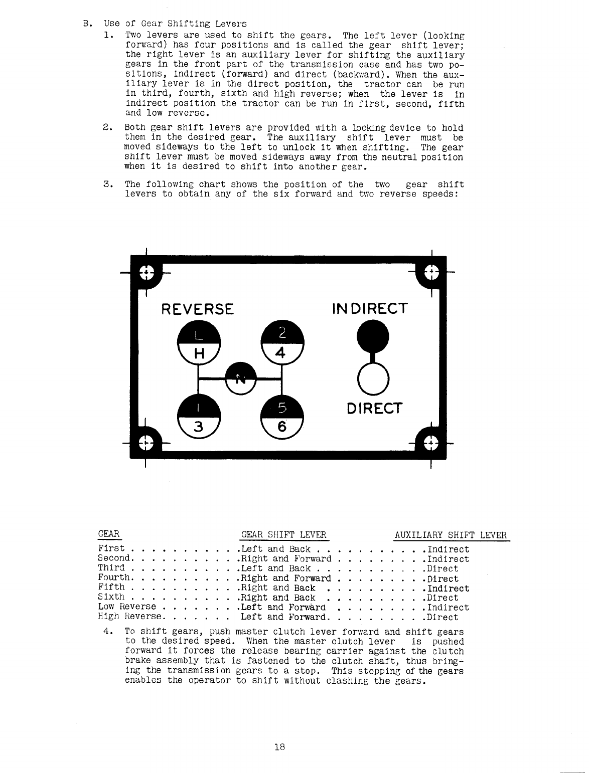
1. Two levers are used to shift the gears. The left lever (looking
forward) has four positions and is called the gear shift lever;
the right lever is an auxiliary lever for shifting the auxiliary
gears in the front part of the transmission case and has two po-
sitions, indirect (forward) and direct (backward). When the aux-
iliary lever is in the direct position, the tractor can be run
in third, fourth, sixth and high reverse; when the lever is in
indirect position the tractor can be run in first, second, fifth
and low reverse.
2. Both gear shift levers are provided with a locking device to hold
them in the des ired gear. The aux lliary shif t lever must be
moved sideways to the left to unlock it ~~en shifting. The gear
shift lever must be moved sideways away from the neutral position
when it is desired to shift into another gear.
3. The following chart shows the position of the two gear shift
levers to obtain any of the six fonvard and two reverse speeds:
REVERSE IN DIRECT
DIRECT
GEAR GEAR SHIFT LEVER AUXILIARY SHIFT LEVER
First •Left and Back .
.
.Indirect
Second. .Right and F'orward •Indirect
Third . .Left and Back. .Direct
Fourth. .R1ght and Forward .Direct
Fifth. .Right and Back •Indirect
Sixth . .Right and Back .Direct
Low Reverse .Left and Forwarn .Indirect
High Reverse. Left and Forward. .Direct
4. To shift gears, push master clutch lever forward and shift gears
to the desired speed. When the master clutch lever is pushed
forward it forces the release bear1ng carrier against the clutch
brake assembly that is fastened to the clutch shaft, thus bring-
ing the
t
ransmrss
t
on gears to a stop. This stopping of the gears
enables the operator to shift without clashing the gears.
18
C. Use of Master Clutch
1. The Master clutch is of highest quality and workmanship and if
given proper care and operated correctly it will give many
hours of carefree operation.
2. To obtain maximum clutch life it is important that in starting
a load, operator must select a gear low enough to insure easy
pick up without clutch slippage. When the correct gear is en-
gaged to handle the load open throttle approximately half way
and pull back steadily on master clutch lever until all slack'
is taken up between tractor and load. Then pull back firmly on
clutch lever to lock clutch in its engaged posi tion at the same
time opening throttle to attain desired speed. To shift to a
higher gear with tractor in motion close throttle at the same
time master clutch is disengaged, select desired higher gear,
engage master clutch and at the same time open throttle.
3. If conditions are such that the tractor can negotiate in sixth
gear with load, start tractor in fifth gear
and
then shift into
sixth gear after tractor has obtained rated speed. Do not slip
the master clutch in an effort to pull an overload. Avoid ex-
cessive wear on the clutch disc facings by using a lower speed
being sure to close throttle to half-way position every time
master clutch is disengaged. When it is necessary to let en-
gine idle for short periods do not idle engine with master
clutch disengaged but shift gears into neutral postt
im
and en-
gage the master clutch.
D. Steering
1. Steering the tractor is accomplished by the use of steering
clutches which are operated by steering levers. Turn the trac-
tor in the desired direction by pulling back
to
the
full
extent
the steering lever on the side toward which the turn is to be
made. The clutches must be engaged slowly and evenly to avoid
excessive wear on them. DO NOT release the leversand let them
fly forward. Do not operate tractor with steering clutches
partially disengaged. Avoid excessive wear of the steering
clutches by releasing and engaging the steeringclutchessmooth-
lyand completely. See topic "Steering Clutch Adjustment.
n
2. In steering the tractor down steep grades with the load pushing
the tractor, the use of the steering clutches is oppOSite to
that of a tractor pulling a load. If it is desired to make a
turn toward the right, the left steering clutch should be re-
leased. The engine being connected to the right track acts as
a brake retarding its progress while the left trackis released
and free to travel faster.
E. Use of Steering Clutch Brakes
1. The steering clutch brakes are for retarding the speed of
01
holding track stationary when the steering clutch on that side
is released for making a turn. In making a turn alwaysrelease
the steering clutch before depressing the brake. They are also
used as service brakes for retarding speed of tractor when
going down grade and to hold tractor stationary. DO NOT OPER-
ATE TRACTOR WITH FEET RESTING ON BRAKE PEDAlB.
2. The brakes can be locked and used as parking brakes when park-
ing the tractor. To hold the brakes in the locked position
the brake pedal lock lever will have to be
held
forward while
applying the brakes. When the brakes are to be released again
a slight pressure on the brake pedal will automatically re-
lease the pedal lock lever.
F. Stopping the Tractor
1. Stopping the tractor is accomplished by disengaging the master
clutch (push lever forward) and applying the steering clutch
brakes. Then SHUT OFF motor. (See topic "Stopping Engine
n)
DO NOT allow tractor to stand with engine idling. If tractor
is to be stopped for ONLY a few minutes, let the engine run at
not less than TWO-THIRDS throttle (approximately 1000 r.p.m.)
with gear shifting lever in neutral position and Master Clutch
engaged to eliminate unnecessary wear on master clutch parts
and pilot bearing.
If
tractor is to be stopped Tanger than a
few minutes, STOP SNGINE.
19
Table of contents
Other Allis-Chalmers Tractor manuals

Allis-Chalmers
Allis-Chalmers H 4 Specifications

Allis-Chalmers
Allis-Chalmers WD Use and care manual

Allis-Chalmers
Allis-Chalmers HD-5 User manual

Allis-Chalmers
Allis-Chalmers HD 6B User manual

Allis-Chalmers
Allis-Chalmers G User manual

Allis-Chalmers
Allis-Chalmers 10 hp User manual

Allis-Chalmers
Allis-Chalmers regent hydro 14 User manual

Allis-Chalmers
Allis-Chalmers ac130 series User manual

Allis-Chalmers
Allis-Chalmers Simplicity 9523 Instruction Manual

Allis-Chalmers
Allis-Chalmers HD-4 Specifications


