Allis-Chalmers B Install guide

SHOPMANUAL
ALLIS-CHALMERS
ModelsB-C-CA-Gtractorserialstampedontopoftransmission.
ModelsRC-WC-WFtractorserial stampedrearfaceofrearaxlehousing.
ModelsWD-WD45tractorserialstampedrearfaceoftransmission.
ModelWD45Dieseltractorserialnumberislocatedatleftbrakecoveror
onleftrearsideoftransmissionhousing.
B-C-CA-RCengineserialstampedontopofleftrearengineflange.
Gengineserialstampedonsideofleftrearengineflange.
WC-WD-WD45-WD45Diesel-WFenginestampedonleftsideofcylinder
block.
Tractor
Model
BUILTINTHESEVERSIONS
TricycleTypeAxleType
SingleDoubleNon- Adiust-
WheelWheelAdjustableable
B
C
CA
G
RC
we
WD
WD45
WF
No
Yes
YM
No
YM
YM
YM
Yes
No
WD45DYM
No
Yes
YM
No
Yes
Yes
Yes
Yes
No
Yes
Yes
No
No
No
No
Yes
No
No
YM
No
YM
YM
YM
YM
No
YM
YM
YM
No
YM
IN D
E
X (ByStartingParagraph)
MODELSB^CAO HCWC.WFm,.^WD45
BELTPULLEY
311311308310310310310
BRAKES
Adjustment300301304305305306306
DrumsR&R300303304B277277282282
R^ne...".*.*.*.*.**..300302304A 305A305A306A306A
CARBURETOR{NotLP-Gas)110110110110HOHO
LP-Gas1"
CLUTCH
Engineclutch160160164166166174174
Engineclutchshait215^
Finaldriveclutch284
Transmissionclutch1"91"9
COOLINGSYSTEM
Fan133133132133134134
Pump*'.;'.'.!'.'.'.'.135135135135135158
Radiator130130131130130130156
DIESELFUELSYSTEM
EnergyCells154
FuelFilters^ 1*"A
InjectionPump' *50
Nozzles1*°
Preheater•."5
QuickChecks. 147
DIFFERENTIAL
Adjustment240240242245247250250
R&Randoverhaul241241243246249251251
ELECTRICAL139139139139139139159
PrintedInU.S.A.COPYRIGHTI960BYTECHNICALPUBLICATIONS,INC.ALL,RIGHTSRESERVED.

INDEXCont.
MODELS
B-CCAG
ENGINE
Assembly
R&R6060
62,65
Cam
followers
737374
Camshaft
858586
Connectingrods
&
bearings
959596
Crankshaft
&
bearings
979798
Cylinderhead
666667
Cylindersleeves
9191
Flywheel
1O3103103
Front
oil
seal
102102102
Mainbearings
979798
Oil
pan105105105
Oil
pump
106106107
Pistons
919192
Pistonpins
939394
Piston
& rod
removal
888889
Pistonrings
919192
Rear
oil
seal
9999JOO
Rockerarms
7575
Tappets
737374
Timinggearcover
787879
Timinggears
828283
Valveguides
707071
Valves
&
valve
seats.
686869
Valvesprings
727272
Valvetiming
737677
FINALDRIVE
Axlehousings
286
Bevelgearsrenew253B254B255B
Bevelgears
adjust.
253254255
Bullgearrenew
266271
Bullpinionbearingsadjust
..267272
Bullpinionrenew
268273
Differentialoverhaul
241241243
Driveunitsoverhaul
285270
^Wheelaxleshafts
266271286
FRONTSYSTEM
Frontaxlemember
5 5 5
Frontsteeringgear
1 i
Main
steering,
Gemmer
IS
Main
steering,
Lavine
Main
steering.
Ross
222222
Pedestal,
adjust
1 1
Pedestal,
overhaul
3 3
Pivot
pin101112
GOVERNOR
Adjustment
115us117
Overhaul
nengna
IGNITIONSYSTEM
BatteryIgnitionTiming140AHOB
MagnetoIgnitionTiming140140
LIFTSYSTEM
Linkage33O
Pump320324328
Testing322325328
Troubleshooting322326
Workcylinder329329329
MechanicalType
POWERTAKE-OFF3U311
REARAXLERefertoFinalDrive
STEERINGGEARRefertoFrontSystem
TORQUETUBE185185
TRANSMISSION
AssemblyR&R2OS
Beisicprocedure205213
Bevelpinion203209222
Clutchshaft215
Countershaft203
Extralowgears', 218
Inputshaft202208220
Mainshaft202208220
Reverseidler204212221
Shiiterforks201207214
RCWCWFWD,WD45
63
73
85
95
97
66
91
103
102
97
105
106
91
93
88
91
99
75
73
80
82
70
68
72
76
246
256B
256
276
277
246
275
276
5
2
2
4
13
115
116
140
340
314
64
73
87
95
97
66
91
103
102
97
105
108
91
93
90
91
101
75
73
80
84
70
68
72
76
249
257B
257
276
277
249
275
276
5
2
26
22
2
4
13,14
119
120
140
340
314
64
73
87
95,95A
97
66
91
103
102
97
105
108
91
93
90
91
101
75
73
80
84
70
68
72
76
258B
258
280
281
282
25;
279
280
5
2
2
4
11
119
120
140A
140
334
324
325
326
329
314
186
223
256B
226
228
226
227
229
225
186
223
257B
226
228
190
WDWD
PriorAfter
Ser.
Ser.
127008
231
230
234
235
233
226
227
229
236
225
232
127007,
WD45
238
237
239B
239C
239A
239D
239
WD45
Diesel
141
142D
144
145B
145C
142
144C
146A
143B
145C
146
146B
144C
145A
144B
144C
145D
143
142D
143B
143C
142B
142/.
142C
143A
258B
258
280
281
282
251
279
280
2
4
11
153A
334
324
325
326
329
3U
190
238
237
239B
239C
239A
239D
239

CONDENSEDSERVICEDATA
(WD45Diesel)
WD45
GENERAL
Tractor
Model
EngineMake
EngineModel45D
Cylinders6
Bore.
Inches3 7/16
Stroke,Inches4 1/8
Displacement.CubicInches230
CompressionRatio15.5:1
PistonsRemovedFrom?Above
MainBearings,Numberof7
MainBearings,Adjustable?No
RodBearings.Adjustable?No
CylinderSleevesWet
Generator.MakeD-R
Starter,MakeD-R
InjectionNozzle.MakeBosch
InjectionPump,MakeBosch
InjectionPump.ModelPSB
TUNE-UP
FiringOrder
1-5-3-6-2-4
ValveTappetGap.Inlet0.010H
ValveTappetGap,Exhaust0.019H
InletValveFaceAngle45"
ExhaustValveFaceAngle45°
InletSeatAngle
45**
ExhaustSeatAngle45"
InjectionTiming.DegreesBTC' 21
TimingMarkLocationFlywheel
TUNE<UP(Conf.)
TractorWD45
ModelDiesel
EngineLowIdleRPM600
EngineHighIdleRPM1975
EngineLoadedRPM1625
BeltPulleyLoadedRPM1460
PTOLoadedRPM548
SIZES-CAPACITIES-CLEARANCES
(ClearancesinThousandths)
CrankshaftJournalDiameter
2.4975
CrankpinDiameter
1.998
CamshaftJournal
Diameter,
Numbers
1.2 and3
1.9985
CamshaftJournal
Diameter,
Number
4
1.2485
Piston
Pin
Diameter
0.9996
ValveStemDiameter
0.3095
Compression
Ring.
Width
1/8
OU
Ring.
Width
3/16
Main
Bearings,
DiameterClearance
2.3-4.5
Rod
Bearings,
DiameterClearance
1.5-3.5
PistonSkirtClearance
4-5
Crankshaft
End
Play
2-7
CamshaftBearingClearance
: 2-4.6
CoolingSystem.Gallons
4V4
CrankcaseOil.Quarts(WithFUter)7
TIGHTENINGTORQUE-Ft.-Lbs.
ConnectingRodNuts30-40
CylinderHeadNuts95-100
FlywheelScrews,...95-105
MainBearingScrews125-135
MODELWD45DIESEL

CONDENSEDSERVICEDATA
(All
Non-DieselModels)
TRACTORMODEL
B (S£
GENERAL•''^^o)
EngineMakeOwn
EngineModelBE
Cylinders4
Bore—Inches3V4
Stroke—Inch€JS
3 V4
Displacement—CubicInches116
CompressionRatioNonLP-Gas4.92
CompressionRatioNonLP-Gas4.67
CompressionRatioNonLP-Gas
CompressionRatioLP-Gas
PistonsRemovedFrom:Above
MainBearingir,Numberof3
MainBearingii,Adjustable?(1)
RodBearings,Adjustable?(1)
CylinderSleeiresWet
ForwardSpeeds3
Generator& StarterMakeD-R
•BandC - 3 speeds.CA- 4 speeds.
TUNE
UP
FiringOrder1,2,4,3
ValveTappetGapOIOH
ValveSeatandFaceAngle45
IgnitionDistributorMakeNone
IgnitionDistributorModel
IgnitionMagnetoMakeF-M
BreakerGap020
MagnetoLagAngle30*
MagnetoImpulseTripsTC
RetardedTimingInchesorDeg.TC
FullAdvancedTimingDeg30**B
MarkIndicating:
RetardedTijning
FullAdvancedTimingFire
MarkLocation—Flywheel,FanPulley.Fly.
SparkPlug—Make
ModelforGasoline
ModelforLowOctane
ElectrodeGap035
CarburetorMakeNonLP-Gaa
Model(Marvel-Schebler)
Model(Zenith)61AJ7
FloatSetting(Marvel-Schebler)
FloatSettincr(Zenith)1 5/32
EngineLowIdJerpm475
EngineHighIdlerpm1850
EngineLoadedrpm1400
SIZES-CAPACITIES-CLEARANCES
(Clearancesinthousandths)
CrankshaftJournalDiameter—Front2.2495
CrankshaftJoumalDia..CenterandRear.2.2495
CrankpinDiameter1.937
CamshaftJoumalDia.,FrontandCenter.
1.7495
CamshaftJournalDia.,Rear
1.7495
PistonPinDiameter8131
ValveStemDiameter11/32
CompressionRingWidth1/8
OilRing—Width3/18
MainBearings.Diam.Clearance.1-2
RodBearings.Diam.Clearance1-2
PistonSkirtClearance
2.5-4.5
CrankshaftEndPlay1-5
CamshaftBearingClearance2-4
CoolingSystem—Gallons2
CrankcaseOil—Quarts4
Transmission—(Quarts
Differential—Quarts
Transmission& Differential—Quarts6
FinalDrive,Each—Quarts75
AddlorPTOand/orBP1
B-C
CA
Own
CE
4
3%
125
6.2
5.75
5.2,4.7
Above
3
(1)
(1)
Wet
*
D-R
RC
Own
4
125
5.75
Above
3
(1)
(1)
Wot
4
D-R
we
WF
Own
4
4
4
201
5.5
Above
3
(1)
(1)
Wet
4
D-R
WD
Own
4
4
4
201
5.75
5.0,5.5
4.5.6.6
Above
3
(1)
(1)
Wet
4
D-R
Cont'L
N62
4
2%
62
6.5
5.4
Below
(3)
2
No
No
None
3
D-R
1,2,4,31,2,4,31,2.4,31,2,4,3
1.3.4.2
B&C.OIOH
CA.012H
45
D-R
1H1735
F-M
.020
30*"
TC
TC
DC
Fire
Fly.
.OIOH
45
None
F-M
.020
30*'
TC
TC
.012H
45
None
F-M
.020
30'
TC
TC
FireFire
By.Fly.
Auto-Lite,ACor
.012H
45
D-R
11H745
F-M
.020
30'
TC
TC
Fire
Fly.
.012C
45
D-R
1111708
Nono
.020
Notch
AN7
AHAuto-Lite
.032.035
-Marvel-Scheblerand
n47
.035
0orJ8Champion
orJllChampion
.035
161J7
15/32
475
2.2495
2.2495
1.937
1.7495
1.7495
.8131
11/32
1/8
3/16
1-2
1-2
2.5-4.5
1-5
2-4
2
4
6
(CA)8
.75
1
161J7
15/32
475
1850
1500
2.2495
2.2495
1.937
1.7495
1.7495
.8131
11/32
1/8
3/16
1-2
1-2
2.5-4.5
1-5
2-4
2
4
4
6
10
.5
i
TSX153
161X7
9/32
15/32
475
1575
1300
2.436
2.4775
2.3745(2)
1.8745
1.8745
.9892
3/8
1/8
3/16
2-3
1-3
2.5-4.5
3-7
2-3
4
6
4
6
10
75
TSX159
161AX
9/32
15/32
475
1720
1400
2.436
2.4775
2.3745
1.8745
1.8745
.9892
3/8
1/8
3/16
2-3
1-3
2.5-4.5
3-7
2-4
31/2
6
17
175
1
.025
Mar.-Scheb.
TSV13
475
2100
1800
1.9995
1.9995
1.4995
1.750
1.250
.5434
5/16
1/8
3/16
15-2.0
15-20
2.0
3-7
3-45
16*
3V2
WD45
Own
WD45
4
4
4.5
226
645
5.25
4.75
7.2
Above
3
(1)
(4)
Wot
4
D-R
h2,4,3
.012H
45
D-R
1111745
None
.020
TC
30^^B
DC
Fire
Fly.
.030
TSX464;
561
9/32
475
1720
1400
2436
24775
23745
1*8745
18745
9892
3/8
1/8
3/16
2-3
1-3
25-45
37
2A
17
^?iy ^'^ °^*^®"^^^' ^2)Onwepriortoserial3665crankpindiameteris1 9995
(3)Refertotextforalternativemethodofpistonremoval.(4)OnenginespriorW45FG1001,bearingshaveshimswhich
onlycontrolcrushofsheUinsert.OnenginesafterW45FG1001,thebearingsar«shimless.•Seeparagraph115

Paragraphs
1-2A
ALLIS-CHALMERS
FRONTSYSTEM-TRICYCLE
AND
AXLETYPES
ADJUSTMENT
OF
PEDESTAL
AND
FRONTSTEERINGGEAR
ModelsC-CA-RC-WC-WD-WD45
1.
C-CA
SINGLEFRONTWHEEL.
Toadjustverticalspindlebearings,
vary
the
shims(4—Fig.
ACl),
lo-
catedbetweentop
of
shaft
and
bearing
cone.
Radiatormust
be
removed
to
obtainaccess
to
shims.
Backlashbetweenbevelgears
of
front(auxiliary)steeringunitshould
be.002,
andis
adjusted
by
varying
the
shims
(9)
afterremoving
the
radiator.
Alternate
the
shimswithgaskets
to
prevent
oil
leaks.
lA.
C-CA
ADJUSTABLEFRONT
AXLE.
Thefrontsupportunit
on
these
modelshouses
the
frontsteeringgear
andcarries
the
pivot
pin
for
the
front
axle.
Internalconstruction,
Fig.AC2,
issame
as
singlewheelmodels.
Toad-
just,followsameprocedure
asout-
lined
for
singlewheel
C andCAin
precedingparagraph.
IB.
C-CADUALFRONTWHEELS.
Toadjustverticalspindlebearings,
vary
the
shims(4—Fig.
AC3)
under
capscrew
(2)at
top
of
shaft.
To
gain
access
to
shims, remove
the
pedestal
unitfrom
the
frontsupport.
Backlashbetweenbevelgears
of
front(auxiliary)steeringgearshould
be.002.Adjust
by
varying
the
shims
(9)beingsure
to
alternateshimswith
gaskets
to
prevent
oil
leaks.
2.
RC-WC-WD-WD45SINGLE
FRONTWHEEL.
On
RC-WC,
and
WD
modelspriorserialWD25129,thewheel
fork
and
verticalspindle
are
integral
asshown
in
Fig.AC4.
On
later
WD,
afterserialWD25128,
and
WD45,
the
wheelfork
is
flange bolted
tothe
verticalspindle
as
shown
in
Fig.ACS.
Adjustverticalspindlebearings
by
varyingshims
(4)
located
attopof
shaftunderneath
the
bearingcone
re-
tainer.
Toadjuststeeringwormshaftbear-
ings,
varyshims(46—Fig.AC6)
toob-
tainfreerotationwithzero
end
play.
Mesh
of
wormwithsector
isnotad-
justable.
Frontwheelbearings
are
adjusted
byvarying
the
number
of
shims(40—
Fig.AC4)locatedbetween
the
bearing
retainer
and
wheel
hub.
2A.RC-WC-WDWD45DUAL
FRONTWHEELS.
To
adjust
thever-
ticalspindleshaftbearings
to
thede-
sired.001-.003
end
play,varynumber
tr—2
20
Fig. ACI-MocfefsC and CA
singl9 wheeltric/cfever-
sionfront support and
front steering gear assem-
bly.
1. Radiatorsupport
2.
Cap
screw
a.Washer
4.
Shims
5.
Bearing:cone&
cup
6.Gasket
7.
Frontsupport
8.Bevelpinion
9.Shims
&
gaskets
10.
Bearing;retainer
12.
Verticalshaft
&
fork
13.
Oil
seal
14.
Bearing
cup&
eon«
16.
Steering
arm
shaft
16.
Oil
seal
17.
Bushinsrs
18.
Bevelsegmentgear
19.
Retaining
nut
20.
Draglink
Fig.ACa-ModefsCandCA
adfustobleaxleversion
frontsupport, front
steof'
ing gear,andaxlo assent'
bly.
1. Radiatorsupport
2.
Capscrew
3.
Washer
4.
Shims
6.Bearingcone
A cup
6.Gasket
7.
Frontsupport
8.Bevelpinion
9.Gasket
10.
Bearingretainer
13.
Oil
seal
14.
Bearingcone
& cup
16.
Steering
arm
shaft
16.
Oil
seal
17.
Bushings
18.
Bevelsegmentgear
19.
Retaining
nut
20.
Draglink
21.
Verticalspindle
&
center
steering
arm
22.
Pivotbracket
23.
Axlemainmember
24.
Spindlesupport
26.
Bushings
26.
Steeringspindle
27.
Bushing(radius
rod^
27

ALLIS-CHALMERS
Paragraphs2B-3
1.
Radiatorsupport
2.
Capscrew
3.
Washer
4.
Shims
6.Gasket
7.Frontsupport
8.Bevelpinion
9.Shims& gaskets
13.
Oilseal
14.
Bearingcone& cup
16.
Steeringarmshaft
16.
Oilseal
17.
Bushings
18.
Bevelsegment
19.
Retainingnut
20.
Draglink
29.
Pedestal
30.
Verticalspindle
31.
Sealretainer
32.
Seal
Fig.AC3—Mode/sC and CA dual wheeltrieyclo version
front support, pedestal, and front steering gear as^
sembly.
14
40
Fig.AC4-ModelsRCand WC single wheel
tricycle version front support and main
steering gear assembly, WD models prior
to serial WD 25129are similar.
1.
Cover
3.
Washer
4.
Shims
6.Bearingcone
7.Frontsupport
10.
Bearingretainer
12.
Verticalshaft&
fork
13.
Oilsea]
32.
Oilseal
34.
Snapring
36.
Sector
38.
Sectorkey
39.
Horizontalspindle
40.
Shims
41.
Bearingretainer
Fig.ACS-Models WD
&
WD4S
single wheel
tricycle version main steering gear and
wheel fork assembly. Effective on tractors
after serial WD 25129.kefer to Fig,AC 4
for
construction
details prior to WD 25T29.
2.
Capscrew
8.Washer
4.
Shims
6.Bearingcone&
cup
9.Gasket
10.
Bearingretains
cone&
18.
Oilseal
14.
Bearing
cup
34.
Snapring
36.
Sector
36.
Verticalspindle
87.
Wheelfork
ofshims(60—Fig.AC8)locatedat
bottomofspindle.
Toadjuststeeringwormshaftbear-
ings,
varythenumberofshims(46—
FigAC6)toobtainfreerotationwith
zeroendplay.Meshofwormwithsec-
torisnotadjustable.
2B.
WC-WDADJUSTABLEFRONT
AXLE.
Theverticalspindlebearings
andfrontsteeringgearonthesemod-
els.
Figs.AC7andAC9,aresimilarto
thesinglewheeltype,havingthe
bolted-ontypeoffork.Adjustment
procedureisalsothesameasoutlined
inparagraph2.
OVERHAULPEDESTAL& FRONT
STEERINGGEAR
ModelsC-CA-RC-WC-WD-WD45
3.
C-CASINGLEFRONTWHEEL.
Todisassemblepedestalandfrontgear
unit,removehoodandradiator,and
withtractorsupportedundertorque
tube,
removefrontwheelandhori-
zontalspindleassemblyfromfork.Re-
movecapscrew(2—Fig.ACl),washer
(3),
andshims(4)fromtopofver-
ticalspindleshaft(12).Removecap
screwsretainingbearingretainer(10)
tofrontsupport(7),andbumpshaft
downthroughupperbearingconeand
frontsupport.Withdrawshaft,gear
andbearingretainerassemblyasa
unitfrombottomoffrontsupport.The
needandtheprocedureforfurther
disassemblywillbedeterminedbyan
inspectionofthepartsandbyrefer-
encetoFig.ACl.Presizedbushings
(17)aresuppliedforsteeringarm
shaft,andifcarefullyinstalledre-
quirenosizingafterinstallation.
Fig.AC6-ModefsRC,WC, WD & WD45
single wheel, dual wheel, and adjustable
axle type steering gear assembly.
42.
Wormshaft
48.
Worm
44.
Retainingpin
46.
Spacer
46.
Shims
47.
Bearingcarrier
48.
Oilseal
49.
Expansionplug

Paragraphs3A-4ALLiS-CHALMERS
3A.Assembleretainer,
oil
seal,low-
erbearing,bevelpiniongearand
ver-
ticalshaft
asa
unit
and
install
in
frontsupportafterinstallingsteering
armshaft
and
segmentgear.Vary
the
number
of
shims
(9)
betweenretainer
andfrontsupporttoprovide.002back-
lashbetweenbevelpinion
and
bevel
segmentgears.Alternateshimswith
gaskets
to
prevent
oil
leaks.Pinion
gear
andtopof
verticalshaft
are
punchmarked
and
should
be
assem-
bled
asinFig.
ACIO.Piniongear
and
segmentgearshould
be
meshed
so
thatsteeringarm
isin
positionshown
in
Fig.
AC11whenfrontwheel
isin
straight-ahead,trailing(castering)
position
and
mainsteeringgear
isin
mid-position.Adjustverticalshaft
bearings
by
adding
or
removingshims
(4—Fig.
ACl)
between
topof
shaft
andbearingconeretainingwasher.
Fork Mounted Wheel.
To
remove
frontwheelandhorizontalspindle,
re-
move
cap
screws
and
axleretainer.
It
will
be
notedthat
the
corkseals
are
installedtoward
the
outside,
andthe
feltsealtoward
the
inside.
3B.
C-CA
ADJUSTABLEFRONT
AXLE.
Exceptthatverticalspindle
in
thefrontsupportterminates
ina
cen-
tersteering
arm
instead
ofa
wheel
fork,
the
externalparts
arethe
same
as
on
thesinglewheelmodelsoutlined
in
the
precedingparagraph.Refer
to
Fig.AC2.
7
35
1
38
.\
I /
61
5958
Fig, ACB-Models
kC, WC, WD &
WD45
dual wheel tricycle version front support,
and main steering gear assembly,
66.
Spindleblock
66.
Horizontalspindl*
67.
Spindlepin
68.
Capscrew
69.
Washer
60.
Shims
61.
Setscrew
1.
Cover
7.
Frontsupport
13.
Oilseal
28.
Sectorsetscrew
30.
Verticalspindle
82.
Oilseal
85.
Sector
88.
Sectorkey
54
2.
8.
4.
6.
9.
10.
18.
14.
22.
28.
24.
26.
26.
34.
86.
36.
60.
62.
64.
Capscrew
Washer
Shims
Bearingconeand
cup
Gasket
Bearingretainer
Oilseal
Bearingconeand
cup
Pivotbracket
Axlemainmem-
ber
Spindlesupport
Bushings
Steeringspindle
Snapring
Sector
Verticalshaft
Centersteering
arm
Thrustwashers
Radiusrodpivot
bracket
Fig, AC9-Models
RC,andWC
non-adjust-
abletype axle version front support
and
main steering gear assembly.
1.
Cover
8.Washer
4.
Shims
6.Bearingcone&
cup
7.
Frontsupport
10.
Bearingretainer
12.
Verticalshaft
13.
Oilseal
32.
Oilseal
34.
Snapring
36.
Sector
38.
Sectorkey
43.
Worm
Fig.ACJ-Models
WD and
WD45 adjustable axle version main
steering gear,
and
axle assembly.
3C.
C-CADUALFRONTWHEELS.
Todisassemblepedestal
and
front
steeringgear,supporttractorunder
torquetube
and
removefrontwheels.
Remove
cap
screwsretainingpedestal
(29—Fig.
AC3)to
frontsupport
(7)
andremovepedestal.Remove
cap
screw(2),washer
(3)and
shimsfrom
top
of
verticalspindleshaft
(30)and
pullpiniongear
(8)off
shaft.With-
drawshaft,bearingcone
andoil
seal
(13)frombottom
of
housing.Theneed
and
the
procedure
for
furtherdisas-
semblywill
be
determined
byanin-
spection
ofthe
parts
andby
reference
to
Fig.AC3.
Presizedbushings
(17)
aresupplied
for
steering
arm
shaft,
and
if
carefullyinstalledrequire
no
sizingafterinstallation.Removal
of
frontsupportfromtractorrequires
removingradiatorcore
and
detaching
supportfromengine.
3D.
Assemblesteering
arm
shaft
andsegmentgearbeforeinstalling
pedestalassembly.Piniongear
and
verticalspindleshaft
are
punch
markedandshould
be
assembled
asin
Fig.ACIO.Varynumber
of
shims(4—
Fig.
AC3)
between
topof
shaft
and
piniongearretainingwasher
tore-
move
all
bearingplay
but
permitting
shaft
to
turnwithoutbinding.Install
pedestalunit
in
frontsupportvarying
thenumber
of
shims
(9)to
provide
.002backlashbetweenpinionand
seg-
mentgear.Piniongear
and
segment
gearshouldbemeshed
so
thatsteering
arm
isin
positionshown
in
Fig.ACll
whenfrontwheels
arein
straight-
ahead,trailing(castering)positionand
mainsteeringgear
isin
mid-position.
4.
RC
-
WC" WD
-
WD45
W O R
M-
SHAFT.
To
disassemblewormshaft,
bump
pinoutof
steeringshaft
uni-
versaljoint
and
wormshaft
and
slide
universaljointback.Removesteering
shaftbearingbracket
(47)and
shims

ALLIS-CHALMERS
(46)fromrear
of
frontsupport
and
withdrawwormshaft
and
gear
as-
sembly.Shims
(46)canbe
varied
in
number
to
adjust
the
wormshaftbear-
ings.
4A.RC-WC-WD-WD45VERTICAL
SPINDLE.
On
singlewheelmodels,
theverticalspindle
is
supported
in
tworollerbearings;
onone
suchbear-
ing
inthe
dualwheelmodels.Refer
toFigs.
AC4,
ACS,AC7,
andAC8.
To
R
&
Ror
renew
the
verticalspin-
dle(30—Fig.
AC8)
and/orspindle
ta-
perrollerbearing,
it
will
be
necessary
tofirst supportfront
endof
tractor
underframerails
and
clutchhousing.
Remove
pin
fromstartingcrank
and
withdrawcrankfromfrontsupport.
Ondualwheeltype,removecover
(1)
PinionGear
TimingMarks
Fig.
ACIO—Correctposition
of
pinion gear
on vertical shaft
is
indicated
by
punch
marks.
Fig, ACll-Models
C and CA
dual,
and
single wheel tricycle versions. Pinion gear
and segment gear should
be
meshed
so
that steering
arm is in
position
as
shown
when front wheel
or
wheels
are in
straight-ahead, trailing (negative
caster^
ing) position,
and
main steering gear
is
in mid-position.
fromfrontsupport
andset
screw
(28)
fromsector
(35).
Using
a
suitable
puller,removesector
andkey.
With-
drawverticalspindle
and
horizontal
(axle)spindleunitfrombottom
of
support.Verticalspindletaperroller
bearingconeand/orcup,
andoil
seals
(13
or32),canbe
renewed
at
this
time.
Onsinglewheelmodels.Figs.
AC4
&AC5,first removeretainerplate(3—
Figs,
AC4& ACS)
and
shims
(4)
from
top
of
verticalshaft.Removestudnuts
whichholdretainer
(10)to
bottom
of
frontsupport.Removeverticalspindle,
bearings,sector
and
bearingretainer
as
an
assemblyfromfrontsupport.
4B.
Whenreassembling,adjust
ver-
ticalspindlebearings
of
dualwheel
models
by
varyingnumber
of
shims
(4—Fig.AC3).
On
single(forkmount-
ed)wheeltypes,adjustbearings
by
varying
the
number
of
shims(4—Figs.
AC4
&
ACS).
4C.
RC-WC-WD-WD45WHEEL
AXLE.
On
dualwheeltype,
the
hori-
zontalspindles(S6—Fig.AC8)
arein-
dividuallyavailable
for
service.Indi-
vidualspindles
canbe
removedfrom
thespindleblockafterremoving
the
frontwheels,retaining
pin(S7)and
adapting
a
combinationpuller.
Horizontal(axle)spindles
and
block
(S5)
canbe
removed
asan
assembly
afterfirst removing
the
wheels,
cap
screw
(58),
washer
(59),
shims
(60)
andspindleblockretaining
set
screw
(61).
Onsinglewheeltype
the
spindle
bearings
are
adjusted
by
varying
the
number
of
shimslocatedbetweenbear-
ingretainer
and
wheelhub.Shims
are
shown
at
(40—^Fig.
AC4).
Paragraphs4A-7A
FRONTAXLEMEMBER
AllModels
5.
Adjustable,Figs.
AC2,7,and
13,
or
non-adjustable.Figs.
AC14&
AC15typefrontaxles
are
either
of-
fered
orare
available
onall
models.
On
all
suchmodels,
the
axlemain
membercompletewithwheelspindles
orknuckles
and
wheels
canbere-
movedfrom
the
tractor
asa
single
unit.Exactprocedurevarieswith
the
variousmodels,
butis
self-evident
af-
terobserving
the
actualtractor.
On
B,
C,CA,G,WDand
WD45,
thera-
dius
rodis
integral
(by
beingwelded
thereto)with
the
axlemainmember.
SPINDLE(KNUCKLE)BUSHINGS
6.Steeringspindlebushings
and
axle
pivotbushingsshould
be
renewed
if
thediametralclearanceexceeds
.020.
Steeringspindlebushingsusually
re-
quirefinal sizing
to
provide.002-.005
clearancebetweenspindle
and
bush-
ing.
To
remove
all
wear
in
systems
employing
the
Lemoinetypespindles
as
in
(26—Figs.
AC2,7,and13),it
may
be
necessary
to
alsoinstall
new
spindles.Recommendedfrontwheel
toe-in
of
0-1/16inch
is
adjusted
by
varying
the
length
oftie
rods.
RADIUS
ROD
7.
MODELSB-C-CA.Rear
endof
radius
rodis
pivoted
ina
removable
bushing(27—Fig.
AC2)inthe
front
end
ofthe
torquetube(clutchhous-
ing).
Bushingrenewalrequired
re-
moval
of
frontaxle
and
integralradius,
rod.
7A.MODELSRC-WC.
To
remove
radius
rod,
detachfront
end
fromaxle
andsliderear
endoff
rear
endof
extendedaxlepivot
pin.
51
23.
Radiusrod(weldedtoasde
member)
24.
Spindlesupport
25.
Bushings
26.
Steeringspindle
33.
Steeringarm
60.
Centersteeringarm
61.
Pivot,radiusrod
63.
Bushing,axlepivot
66.
Dustshield
67.
Tierod& socket
68.
Pivotpin
Fig.
AC13—Model
G
adjustable axle
has
Lemoine type
knuckles, Pndius
rod is
welded
to
axle main member.

Paragraphs8-18
8.MODELSG-WD-WD4S.Radius
rodisintegralwithfrontaxleandis
supportedinanunbushedbracketon
WDandWD45buttheG isprovid4'd
witha removablebushing.
9.MODELWF.Toremoveradius
rod,detachfrontendfromaxleand
removeboltattachingrearendtosup-
portplateonclutchhousing.
PIVOTPIN(KINGPIN)
10.
MODELB.Pivotpiniswelded
tofrontaxlesupportplateandaxle
isretainedtopivotpinbya cotterpin.
Onadjustableaxlemodels,axleis
equippedwitha bushingforthepivot.
11.
MODELSCA-WD-WD4S.Pivot
pinisweldedtoaxlemainmember
andridesinanunbushedbracket.
12.
MODELG.Pivotpincanbe
pressedoutofaxlemainmember.It
isprovidedwitha splittyperenew-
ablebushinglocatedinfrontframe.
13.
MODELSRC-WC.Pivotpincan
beremoved,afterremovingradiusrod,
bydisconnectingpivotpinbracket,
removingsetscrewfromaxle,and
drivingpinrearwardoutoffrontsup-
portandaxle.
14.
MODELWF.Pivotpincanbe
drivenoutoffrontsupportafterre-
movingcotterpinfrombehindaxle
andretainingpinfromsupport.
MAINSTEERING
GEAR
Serviceinformation in this section applies
to models B, G,and WF, which have only a
main steering gear, and to the main steering
ing gear only on models C and CA, For in-
formationon the adjustment and overhaul oi
the front or auxiliary gear on models C, CA,
RC, WD, and WD45 refer to paragraphs 1
through 4A.
B-CGemmerGear
(Refer to paragraphs 1,lA,IB,3,3A,
3Band 3Cfor model C front steering
gear, and to paragraphs 22,23,and 24
for Ross main gear.)
16.
Endplayofwormshaftandsec-
torshaftmustbeinadjustmentbefore
adjustinggearbacklash.Disconnect
draglinkorremoveballarm(steering
arm)toremoveloadfromgearand
permitlocatingmid-position.
17.
WORMSHAFTENDPLAY.
Firststepinmakingthisadjustmentis
toremovethefueltank.Toreduce
playinwormshaftbearings,remove
thesteeringwheel,loosenclamp(81—
Fig.AC16)andslidetube(82)up
column.Removecapscrewsretaining
housingcap(80)tohousing(onB and
Cworkthroughtoolboxopeningto
removetwolowerscrews),andslide
tubeupandawayfrombearingre-
tainer.Removeshims(78)untilworm
shafthaszeroendplay,butrotates
freely.Whenre-positioningtube,be
ALLIS-CHALMERS
sureupperenddoesnotbindsteering
wheel.
18.
SECTORSHAFTENDPLAY.It
isadvisabletoremovethestarter
motorforbetteraccesstothisadjust-
ment.Toadjustsectorshaft(8S)end
play,placesteeringwheelabout%
Fig.AC14—ModelB non-ad/ustableaxle version—front and top views.
23.
Radiusrod(welded
toaxlemember)
26.
Bushings
26.
Steeringspindle
27.
Bushing(radiusrod)
68.
Pivotpin
26
72
Fig.ACI5~ModelsftC andWC non-adjustable axle version-front view.
20.
Drag link
22.
Frontsupport
23.
Axlemember
26.
Bushing
26.
Spindle
62.
Thrustwasher
68.
Pivotjpin
69.
Setscrew
70.
Oilseal,hub
71.
Spindlelockstud
72.
Expansionplag
73.
Spindlepia
10

ALLIS-CHALMERSParagraphs19-22
turnfromeitherextremeposition,
loosenlocknut(87)andturnadjusting
screw(86)clockwisetoreduceend
play.Besurehousingnuts(92)and
(93)aretightwhenmakingthisad-
justment.Allendplayinsectorshaft
75
87
90
88
Fig.ACI6--aeminersteering gear assembly as vsetfin early production B and
C
models.
75.
Expansionplug
76.
Housing
77.
Worm£ shaft
78.
Shims& gaskets
80.
Housingcover
81.
Tubeclamp
82.
Jackettube
83.
Bushing
86.
SectorA shaft
86.
Adjustingscrew
87.
Locknut
88.
Eccentricrivet
89.
Bushing
90.
Steeringarm(ballarm)
91.
Sectorshafthousing
92.
Housingnut
93.
Jamnut
94.
Conicallockring
96.
Eccentricsleeve
96.
Oilseal
907576
100
9689
,^
Hg, ACir—koss steering gear assembly (exploded view) as used in later and current
production B, C, and all
CA
tractor models.
76.
Expansionplug
76.
Housing
77.
WormA shaft
78.
Shimsft gaslcets
80.
Housingcover
81.
Tubeclamp
82.
Jackettube
83.
Bushing
86.
Sector& shaft
89.
Bushings
90.
Steeringarm
96.
Oilseal
99.
Sidecover
100.
Housingbracket
101.
Oilseal
103.
Snapring
104.
Bearingcup
106.
Bearingball
106.
Gasket
shouldbeeliminatedbutgearshould
notbind.
19.
GEARMESH.Toadjustgear
mesh,loosencolumnbracketclamp
andlocatemid-positionofgearby
turningsteeringwheelfromoneex-
tremepositiontotheotherthenback
halfway.Withgearinmid-position,
loosenhousingretainingnuts
V4,
turn
andeccentricsleevejamnut(93)V2
turn.
Slowlyturneccentricsleeve(9S)
clockwisewhilecheckingamountof
gearbacklashbyfeelingplayinball
arm.(Turningeccentricsleeveclock-
wisemovessteeringgearhousing
downinrelationtosectorshafthous-
ingbringingwormandsectorinto
deepermesh,therebyreducinggear
backlash.)Adjusteccentricsleeveun-
tilplayinballarmisbarlypercepti-
ble,
whensteeringwheelisinmid-
position.Makelastadjustmentofthe
eccentricsleeveintheclockwisedi-
rection.Aftermeshadjustmentiscom-
pleted,tighteneccentricsleevejam
nut,thenhousingnuts.
20.
CENTRALIZATION.Checkgear
centralizationbydeterminingamount
ofplayinballarmwhenwheelis
turned% turntotherightand%
turntotheleftofmid-position.Ifplay
isnotthesameonbothsidesofmid-
position,loosenhousingnutsandec-
centricsleevejamnutV4 turnand
centralizegearbyturningeccentric
rivet(88).Ifthereismoreplaytothe
right,turnrivetclockwiseandifmore
totheleft,turnrivetcounterclockwise.
Aftergearhasbeencentralized,re-
adjustgearijieshwitheccentricsleeve
aspreviouslydescribed.Ballarm
shouldbepositionedonsectorshaftso
thatsteeringgearisinmid-position
whenwheelsarestraightahead.
21.
OVERHAUL.Gearunitshould
beremovedfromtractor.Procedureis
readilyevidentfromanexamination
ofFig.AC16.Whenreassembling,in-
stallwormgearandshaftassembly
andadjustwormgearbearingsbefore
assemblingbalanceofsteeringgear.
Forcompleteadjustmentprocedure,
refertoparagraphs17through20.
B-C-CA-G-WF(RossGear)
(Refer to paragraphs 1,lA, IB, 3,
3A,3Band 3Cfor models C-CA front
gear and to 16through 21for Gemmer
main gear.)
Beforeadjustingthegear,discon-
nectdraglinkorremovesteeringarm
toremoveloadfromgearandpermit
locatinginmid-position.
22.
WORMSHAFT(CAM)END
PLAY.OnB,C,andCA,firststepin
makingthisadjustmentistoremove
thefueltank.Toreduceplayincam
11

Paragraphs23-27ALLIS-CHALMERS
Fig.ACl8—Ross steering gear installation
on models
B, C,and
CA. Wormshaff bear-
ings adjustment
can be
made after
re-
moving
the
fuel
tank.
76.
Housing
78.
Shims& gaskets
80.
Housingcover
82.
Jackettube
86.
Adjustingscrew
87.
Locknut
108.
Tube clampbolt
Fig.AC79—RosssfeeringgearInsfallaflon
onmodel
G
tractor.
78.
Shims& gaskets
80.
Housingcover
81.
Tube clamp
82.
Jackettube
86.
Adjustingscrew
99.
Sidecover
108.
Tubeclampbolt
109.
Housingcover
capscrews
(worm)bearings,removesteering
wheel,loosencolumnjackettube
clampFigs.AC17,AC18,AC19
andAC
20,
and
supportclamp;thenslide
tube
(82)up
column.Remove
cap
screwsretaininghousinguppercover
(80)
to
housing
(onB,C,andCA,
workthroughtool
box
opening
tore*
move
two
lower
cap
screws).Remove
shims
(78)
untilshaft
has
zero
end
play,
but
rotatesfreely.
23.
STUD(LEVERSHAFT)MESH.
OnB,
C,and
CA,
itis
advisable
tore-
move
the
startingmotorbefore
at-
temptingthisadjustment.Locate
mid-
position
of
steeringgear
by
turning
steeringwheelfrom
one
extremeposi-
tion
tothe
other,thenbackhalf-way.
Withgear
in
mid-position,loosenlock-
nut(87—Fig.AC18
or
AC20)
and
turn
adjustingscrew
(86)
clockwiseuntil
endplay
in
levershaft(crossshaft)
is
78
77
97
Fig.
AC70—ROSS
steering gear assembly
as
used
on
later production model
WF
fracfor.
76.
Expansionplug
77.
Worm& shaft
78.
Shims& gaskets
80.
Housingcover
81.
Tube clamp
82.
Jackettube
83.
Bushing
86.
Sector& shaft
86.
Adjustingscrew
87.
Locknut
89.
Bushings
90.
Steeringarm
96.
Oilseal
97.
Snapring
99.
Sidecover
barelyperceptible.
Be
surehousing
cover
cap
screws
areall
tightwhen
makingthisadjustment.Shaftshould
have
an
increasedamount
ofend
play
whengear
is
movedeither
wayoff
the
mid-or
highpoint.Steering
arm
should
be
positioned
on
levershaft
sothatsteeringgear
isin
mid-position
whenwheels
are
straightahead.
Onmodel
G,
steeringwheelshould
bepositioned
on
levershaftsplines
in
suchmannerthatwithfrontwheels
pointingstraightahead,
the
cutaway
section
of
steeringwheel
is
located
between
the
12
and4
o'clockpositions.
24.
OVERHAUL.
On
models
B,C,
and
CA,
removal
ofthe
gearunit
re-
quiresremoval
of
fueltank,starting
motor
andits
linkage,negative
bat-
terycable,steeringwheel
and
shroud
retainingbolts.Afterunboltingfrom
torquetube,withdrawunitforward
until
itis
freefromshroud.
The
inner
races
forthe
wormshaftballbearings
areformed
bythe
groundends
ofthe
worm
orcam
itself.
The
levershaft
is
supported
ontwo
renewablebushings,
which
are
pressedinto
the
gearhous-
ing.Whenreinstalling
the
jackettube
(82)
the
notch
atits
lower
end
should
be
up,to
preventgreaseleakage.
Of
the
cap
screwsretaining
the
column
shaftcover,
the
lower
oneor
ones
re-
ceive
the
greasesealingcopperwash-
ers;
the
other
cap
screws
are
provided
withlockwashers.
RC-WC-WD-WD45
Steeringgear
on
thismodel
islo-
cated
in
frontsupport.Refer
to
para-
graph
4 and4Afor
adjustment
and
repairdata.
WF(LavineGear)
Beforeadjusting
the
gear,discon-
nectdraglink
or
removesteering
arm
toremoveloadfromgear
and
permit
locatingmid-position.
26.
WORMSHAFT
END
PLAY.
To
reduceplay
in
wormshaftbearings,
removeshims(78—Fig.
AC21)
from
betweenhousinglowercover
(80)and
housing
(76).Allend
playshould
be
removedfromwormgear
but
shaft
should
not
bind.
27.
GEARMESH.Locatemid-posi-
tion
of
steeringgear,withdraglink
disconnected,
by
turningsteering
wheelfrom
one
extremeposition
to
theother,thenbackhalf
way.
With
gear
in
mid-position,loosenlocknut
andturnadjustingscrew
(86)
clock-
wise
to
reduce
end
play
in
trunnion
shaft
(8S).Be
surehousingcover
re-
taining
cap
screws
are
tightwhen
makingthisadjustment.When
end
play
inthe
trunnionshaft
is
reduced,
drive
nut(107)is
mesheddeeperinto
wormgear
(77)and
backlash
isre-
12

ALLIS-CHALMERSParagraphs28-65
77
78
76.
Housing
77.
Worm& shaft
78.
Shims& gaskets
80.
Housingcover
81.
Tubeclamp
82.
Jackettube
83.
Bushing
86.
Trunnionshaft
sr*.Adjustingscrew
8!>.Hushings
90.
Steeringarm
96.
Oilseal
98.
Thrustball
99.
Sidecover
107.
Drivenut
Fig.AC2I—tavinesfeeringgearassembly as used on early production model
WF
tractor.
duced.Steeringarmshouldbeposi-
tionedontrunnionshaftsothatsteer-
inggearisinmid-positionwhen
wheelsarestraightahead.
28.
OVERHAUL.Gearunitshould
beremovedfromtractor.Procedure
fordisassemblyisreadilyevidentfrom
anexaminationofFig.AC21.
NON-DIESEL
ENGINEANDCOMPONENTS
R&RENGINEWITHCLUTCH
Models
B-C-CA
60.
Removehoodanddisconnect
fuellines.Supporttractorunder
torquetube.Disconnectsteeringdrag
link(alsoradiusrodretainingnutif
used),
upperandlowerradiatorhoses,
andlightwires.Withfrontaxleand
radiatorandgrilleunitsupported,re-
movefournutswhichretainfront
supporttoengine.Movethefrontsup-
portradiatorandpedestaloraxleas
aunit,awayfromtheengine.Discon-
nectgovernorcontrol,wiresatcoil,
andgenerator,chokerod,andfuel
line.
Withweightofenginesupported
byhoist,removethefourboltsretain-
ingenginetotorquetubeandremove
engineunit.
ModelG
62.
Toremoveenginefromthetrac-
tor,draincoolingsystemandoilsump.
Shutofffuelsupplyattankconnec-
tion.Removehood,hoodsupport
(sheetmetalcoverfromtiminggear
coverendofengine)andupperand
lowerradiatorhose.Removethe
drawbarguide.Disconnectstarter
controlrod,chokerod,headlightwire,
andbatterycableatstarter.Discon-
nectfuellineandremovethrottlerod.
Theenginemaybesupportedfrom
theextremeendsofthefanshaft
bearingsupports,orbyusinga proper
lifthookthreadedintothenumber
threesparkplughole(cylindersare
numberedfromtiminggearend).Re-
movestartingmotorandboltsretain-
ingenginetoclutchhousing.Engine
may nowberemovedbypullingsame
forwardtoreleaseclutchshaftfrom
clutchplate.
ModelRC
63.
Removehoodanddisconnect
fuellines,electricalconnections,and
controls.Removeradiatorandcrank
pinlocatedjustbehindfrontsupport
andpullcrankforward.Supporten-
gineinhoistandremoveenginefront
support,flywheelcoverandcap
screwsretainingenginetoclutch
housing.
ModelsWC-WD-WF-WD45
64.
Removehoodandradiator.Dis-
connectfuelline,aircleanerhoseand
generatorwire.Disconnectchokerod
andthrottlerod.Supportenginewith
ahoist.Attachtheliftbrackettotwo
oftherockershaftsupportstuds.Re-
moveuniversaljointretainingpin
fromsteeringwormshaftandslide
steeringshaftanduniversaljointrear-
ward.
Removetwocap screwsandtwo
boltsretainingfrontenginesupport
toframerailsandtiminggearcover.
Removedustshieldfromfrontlower
faceofclutchhousing.Removecap
screwsretainingenginetoclutch
housing.Removestartingcranksup-
portandpullstartingcrankforward
against^ringi5ressure.Slideengine
forwarduntilfreeofclutchhousing
dowelpins.Raisefrontofengine
untilcrankshaftpulleyclearstheaxle
frontsupportandatthesametime
slidetheengineforwarduntilthe
clutchclearstheclutchhousing.Raise
engineclearofframerailsandatthe
sametimetipit^towardleftsideof
tractorsoastoclearsteeringshaft.
Shimslocatedbetweenenginefront
supportandlowersideoftiminggear
covershouldbevariedtoobtainpro-
perenginealignment.Thecheckfor
correctengine-to-clutchhorizontal
alignmentshouldbemadeafterthe
engineisboltedtotheclutchhousing
andbefore thefrontsupporttotiming
gearcovercapscrewsarereinstalled.
R&RENGINEANDCLUTCH
HOUSINGASA UNIT
ModelG
65.
Clutchhousingandenginecan
beremovedasa unitbyfollowing
theengineremovalproceduretothe
pointofremovingtheenginetoclutch
housingretainingbolts.Atthistime
disconnectclutchpedalrodfrom
throwoutbearingforkandunhook
thebrakereturnspringsatthebot-
tomoftheradiatorsupport.Usethe
sameliftarrangementasforengine
removal,exceptthebalancepointwill
beabout4 inchesclosertoflywheel
endofengine.Removeclutchhous-
ingtotransmissioncaseretaining
13

Paragraphs66-70
bolts.
Engineandclutchhousingunit
maynowberemovedbypullingsame
rearwardtounmeshclutchshaftgear
frommainshaftintermediategear.
CYLINDERHEAD
AllExceptModelG
66.
Toremovecylinderhead,re-
movehoodanddraincoolingsystem.
Removecylinderheadcover(rocker
levercover)androckerarmsassem-
bly.Unboltcarburetorfrommanifold
andallowsametohangonairfilter
hose.
Disconnectwateroutletcon-
nectionandoilconnectiontocylinder
head.Removecylinderheadcap
screwsornuts(alsoremovewater
manifoldonWC,WD,WD45andWF)
andliftoffhead.Whenreinstall-
ing,tightenheadnutsorcapscrews
progressivelyandfromthecenterout-
ward.Retightenafterenginehas
reachedoperatingtemperature.Tight-
enmodelsB,C,CA,andRCcapscrews
to60footpoundstorque.Tightenmod-
elsWC,WD,WD4SandWFV2inch
studsto70footpoundsand% inch
studsto2Sfootpoundstorque.
ModelG
67.
Toremovecylinderhead,first
removehoodandsupport,anddrain
coolingsystem.Removecarburetor
airintake,aircleaner,instrument
panel,fanassembly,sparkplugwire
bracket,andupperradiatorhose.Re-
movecylinderheadretainingcap
screwsandnutsandliftoffhead.
Whenreinstalling,tightenhead
nutsprogressivelyandfromthecen-
teroutward.Retightenafterengine
hasreachedoperatingtemperature.
Tightenthe% inchcapscrewstoS3-
S7ft.lbs.torque.
VALVESANDVALVESEATS
AllExceptModelG
68.
OnB,C,andRCtappetsshould
besethotto.010forinletandex-
Flg.
AC23-WDengines after engine serial
299173, and engines 262650 through 263-
224 andWD4S are factory equipped with
kotocap positive type valve rotators for
the exhaust valves, kotators are also
available for service on the WC and WF
engines.
haustvalves.OnCA,WC,WD,WD-
45andWFtappetsshouldbesethot
to.012forbothinletandexhaust.
Inletvalveswitha slightlylarger
headthanexhaustvalvesseatdirectly
inthecylinderhead.However,inlet
valveseatsinsertsareavailablefor
service.Oversizeexhaustvalveseat
insertsareavailableforinsertre-
newal.Bothinletandexhaustvalves
havea faceandseatangleof4Sde-
grees.
Desiredseatwidthis1/16inch.
Seatscanbenarrowed,using30degree
and60degreecutters.
EnginesinWD& WD4Safteren-
gine299173andengines262650
through263224,arefactoryequipped
withRotocappositivetypevalvero-
tatorsfortheexhaustvalves.Fig.
AC23.
Theserotatorsarealsoavail-
ableforserviceontheWCandWF
engines.Theyrequirenomaintenance
butshouldbevisuallyobservedwhen
engineisrunningtomakesurethat
eachexhaustvalverotatesslightly.
Renewtherotatorelementofany
exhaustvalvewhichfailstorotate.
ModelG
69.
Tappetsshouldbesetcold.012
inlet,andexhaust.Inletandexhaust
valvesarenotinterchangeable.Inlet
valveshaveroundpintypespring
lockswhiletheexhaustvalves,which
areprovidedwithRoto-valverelease
typerotators,havesplitconetype
locks.
Allvalvesseatdirectlyinthe
cylinderblockandhavefaceandseat
anglesof45degrees.Desiredseat
widthis3/64inch—recutifwiderthan
1/16inch.Seatsmaybenarrowed,us-
ingISdegreeand75degreecutters.
Agaporendclearanceofnotless
than.001andnotmorethan.006be-
tweenendofexhaustvalvestemand
bottomofRoto-valvecupshouldexist
whenvalveisonitsseat.Referto
Figs.
AC24andAC2S.
ALLIS-CHALMERS
VALVEGUIDES
AllExceptModelG
70.
Thecastironpresizedshoulder-
lessvalveguidesarepressedintothe
cylinderheadwitha piloteddriftuntil
scribelinemarkonguideisfiush with
machinedsurfaceofvalvespringseat.
RefertoFig.AC32,forWD& WD4S
installation.Inletguidesare7/32inch
Fig.
AC2S—A
gap or end clearance (O), of
.001-.006shouldexist in a koto-valve in'
stallation when the valve Is on Its
seat.
Fig, AC24—G tractor engine (N62 Confl-
nental) exhaust valves are provided with
koto-valve release type rotators. Fig, AC26—ModelsB, C, CA, and RCengine
valvesystem—end
view*
14

ALLIS-CHALMERS
longerthanexhaustguidesandextend
fartherintotheports.Desiredclear-
anceoftheinletandexhaustvalve
stemsintheguidesis.002S-.0045.
ModelG
71.
Inletandexhaustguidesare
interchangeable.Theyarepresized,
butshouldbereamedafterinstallation
to.316whichwillremoveanylocal-
izedhighspots.Guidesshouldbe
pressedordrivenintotheblock,using
apiloteddrift.002smallerthanbore
ofguide,untiltopofeachguideis
25/32inchbelowgasketsurfaceofthe
cylinderblock.Desiredclearanceof
inletvalvestemsinguidesis.002—
ofexhauststems.0035.Ifinletclear-
anceexceeds.005,orexhaustclear-
anceexceeds.007,renewtheguides.
VALVESPRINGS
72.
ModelG,inletandexhaustvalve
springsareinterchangeable.Each
springshouldrequire13-17lbs.pres-
suretocompressittoa heightof1%
inchesfromitsfreelengthof1 13/16
inches.
Springcanberemovedwithoutre-
movingheadbyscrewingadjusting
screwdownagainstlockandholding
valveupwithwirethroughspark
plughole.
Onothermodelsspringshould
require33-39lbs.pressuretocom-
Paragraphs71-75
Fig.
AC2a-ModelsWC,WD,WD45 and WF cylinder head and rocker arm assembly
showing exhaust valve seat inserts. Inlet valve seat inserts are available for service,
1.
Retainer4.Support7.Oiltube
2.
Washer 5.Rockerarm8.Rockerbusbinir
3.
Supportstudnut6.Oilcollar
pressittoa heightof1%inchesand
SS-65lbs.ata heightof1 S/16inches.
Springswhicharerusted,distorted,
ordonotmeettheforegoing pressure
specificationsshouldberenewed.On
overheadvalvemodels,springsmay
berenewedwithoutremovingthe
cylinderheadafterremovingthe
rockershaft.
CAMFOLLOWERS(Tappets)
AllExceptModelG
73.
Mushroomtypetappets(cam
followers)operatedirectlyinma-
1.
Pintypelock
2.
Inletvalve
3.Valvesuide
4.
Valvespring
6.Springretainer
6.Tappetscrew
7.
Locknut
8.Valvetappet
9.Camshaft
10.
Thrustplate
11.
Camgear
16.
Rotocap
18.
Splitconelock
Id.Exhaustvalve
IS-
IS-^
Fig.
AC27-Model G camshaft, valves and tappets. Note governor vent (X) in camshaft
and items (16) and (IB) which are used only on the exhaust valves.
chinedboresofthecylinderblock.
Tappetsarefurnishedonlyinstandard
sizeandshouldhavea clearancein
blockboresof.OOOSto.002witha
maximumallowableclearanceof.007
forservice.Anytappetcanbere-
moveda^terremovingtheoilpan,
rockerarmsandshaftsassembly,oil
pump,timinggearcoverandcam-
shaft.Tappetsshouldbeadjustedto
.010hotforB,C,andRC;.012hot
forCA,WC,WD,WD4SandWF.
ModelG
74.
Barreltypetappets(camfol-
lowers)operatedirectlyinthebores
machinedinthecylinderblock.Tap-
petscanberemovedbyfirst remov-
ingthevalvespringwhichisaccom-
plishedbyturningtheadjustingscrew
downagainstthelockandholdingthe
valveupwitha wirethroughthe
sparkplughole.Nowremovethetap-
petscrewandlockelementfromthe
tappet.Tappetsshouldbeadjusted
coldto.012forbothinletandexhaust
valves.Tappetsarefurnishedonlyin
standardsizeandshouldhave.001
clearanceinblockbores.
VALVEROCKERARMS
AllExceptModelG
75.
Rockerarmsandshaftsunit
canberemovedafterremovingthe
hood,valvecover,oillinefromcyl-
inderheadtorockerarmsandfour
shaftsupportretainingnutsandwash-
ers.
Todisassembletherockerarmsand
shaftsassembly,removehairpintype
retainerorcotterpinandwasherfrom
endsofshaft.Thevalvecontacting
surfaceofrockerarmscanberefaced,
butthesurfacemustbekeptparallel
torockerarmshaftandoriginalradius
maintained.Desiredclearancebe-
tweena rockerarmbushinganda new
15

Paragraphs76-80
shaftis.002-003. Ifclearanceexceeds
.008,
renewtherockerarmandbush-
ingunitand/orshaft.Earlyproduc-
tionengineswereequippedwith
forgedrockerarmswhichhavebeen
discontinuedandreplacedbybuilt-up,
stampedsteeltypeonallmodels.
Rockerarmbushingsarenotavailable
separatelyexceptforthediscontinued
forgedtyperockerarms.
Theinletvalverockerarmcanbe
identifiedbya millednotchlocatedon
itsuppersurfacebetweenshaftand
valvestemend.Reinstallrockerarm
shaftswiththeoilingholestoward
thecylinderhead.
OnB,C,CA,andRC,thegrooved
supportstudshowninFig.AC29
shouldbeinstalledinrearstudhole.
Thisstudactsasanoilpassageto
lubricaterockershaft.
Onallmodelsbesuretoinstall
copperorcompositionwashersbe-
tweencoverandcovernutstoinsulate
noise.
VALVETIMING
AllExceptModel
G
76.
Valvesarecorrectlytimedwhen
markedtoothofcrankshaftgearis
meshedwiththecorrectmarkon
camshaftgear.Ifcamshaftgearhas
twoidenticalmarks,theoneopposite
thekeywayshouldbemeshedwith
markedtoothofcrankshaftgear,and
theoppositeonewiththemarkonthe
magnetogear.All"CE"enginesand
"BE"
enginesnumberedBE12550and
higherhavecamshaftgearmarked
witha straightlineandan"O"ora
dot.Ontheseengines,meshthe
straightlineofthecamshaftgearwith
thesimilarlymarkedtoothonthe
ALLIS-CHALMERS
Fig, AC29~Models
B, C,
CA,
and
RCrocker
arms, kocker shaft rear support stud
is
grooved
to
provide
oil
passage
to
rocker
arms.
Fig, AC30
-
Timinggear
marks
on all "d"
engines
and
"BE"
engines
num-
bered BiJ25S0
and up. On
"BE" engines prior
to
BB-
12550,
the
camshaft gear
has
two
identical marks;
the
one
opposite
the key-
way should
be
meshed
with
the
crankshaft
gear.
crankshaftgearandthe"O"mark
withthe**O"markonthemagneto
gear.RefertoFig.AC30.
Numberonecylinderinletvalve
opensattopcenterandexhaustvalve
closes10degreesaftertopcenter.
Tocheckvalvetimingwhenengine
isassembled,adjustnumber1 inlet
valveclearanceto.014.Inserta .004
feelergagebetweenrockerarmand
valvestemandrotatecrankshaftuntil
aslightdragisfeltwhiletryingto
withdrawthefeelergage.Atthistime,
thetopcentermarkonfiywheel should
beinregisterwith,ornotmorethan
V4incheitherwayfromcenterofin-
spectionport.Resettappetgapto
properclearance.Onflywheelswhich
donothavea topcentermark,the
topcenterpointcanbeestablishedby
measuringbackfromthe"Fire"or
"F"
markorbyusingthestarterring
gearteethasa basisforcalculation.
OntheWD,whichhasa ringgearof
100teeth,TCwould be8 1/3teeth
(3yg"onrim)afterthe"Fire"mark,
asshowninFig.AC46.
Model
G
77.
Tochecktimingwhenengine
isassembled,adjustbothtappetsof
No.
4 cylinderto.020,thencranken-
gineuntilNo.4 pistonisattopcenter
ontheexhauststroke.Thispointis
indicatedwhenthenotchoncrank-
shaftpulleyisVsinchpastthecenter
oftheinspectionport,locatedinthe
hoodsupportasshowninFig.ACS3G.
Ifvalvesarecorrectlytimed,both
valveswillnowbeclosedanditshould
bepossibletorotatebothtappetb
withthefingers.
TIMINGGEARCOVER
ModelsB-C-CA
78.
Toremovecover,removetractor
hoodandsupporttractorundertorque
tube.
Removeradiatorandaxleor
pedestalandfrontsupportasa single
unit.Disconnectgovernorcontrols,
andremovegovernorcontrolhousing.
Removecrankshaftpulley,fanblades.
andfanbelt.Onsomeengines,the
front-centeroilpanretainingstudis
weldedtotheangleironontiming
gearcover,necessitatingremovalof
theoilpanassembly.Wherethesfud
isnotwelded,covercanberenewed
withoutremovingtheoilpan,butas
aprotectionagainstsubsequentoil
leaks,
itisadvisabletoalwaysremove
theoilpan.Ifoilpanisnotremoved,
theoilpangasketmustbeverycare-
fullyseparatedfromthetiminggear
cover.Screwsofthreedifferent
lengthsareusedtoretainthecover;
besuretheyareinstalledinthecor-
rectlocations.
Model
G
79.
Althoughitispossible torenew
crankshaftfrontoilsealwithout
removingthetiminggearcover,our
suggestionistoremovethecover,
whichentailslittleadditionalwork.
Toremovethetiminggearcover,re-
movethehood,hoodsupportand
crankjaw.Disconnectcarburetorlink
rodandgovernorspring.Remove
pulley,usinga pullerandtwo% inch
capscrew§toattachsame.Donot
threadscrewstoofarintopulley,as
theymaydamagethecasttiminggear
cover. Removethecovertocylinder
blockcapscrewsandwithdrawthe
cover.
Thesealwhichconsistsofanouter
feltwasherandaninnerfianged ring
oftreatedleather,shouldbeinstalled
withthelipoftheinnerelementfac-
ingthetiminggears.
ModelsRC-WC-WD-WD45-WF
80.
Itispossible torenewcrank-
shaftfrontoilsealwithoutremoving
thetiminggearcover. Theoilsealcan
berenewedafterremovingthehood,
radiator,crankshaftpulleyandfront
sealretainer.Loosentiminggearcover
retainingcapscrewstofacilitatecen-
teringoilseal.Latestsealsareoffelt
facedwithneoprene.
16

ALLIS-CHALMERSParagraphs82-85
Toremovetiminggearcover,first
removehoodandradiator.Remove
startingcrankextensionpinand
loosenextensionbracket.Loosenset
screwretainingpulleytocrankshaft
andremovepulley.Disconnectthrottle
andgovernorlinkage.Blockupfront
endofengineandremoveenginesup-
port.OnRC,thefront-centeroilpan
studmaybeweldedtotheangleiron
ontiminggearcover;inwhichcaseit
willbenecessarytoremovetheoil
pan.OnWC,WD,WD45& WF,itis
notnecessarytoremoveoilpan,but
removalisrecommendedasa means
ofprotectingagainstsubsequentoil
leakswherepanjoinsthebottomface
ofgearcover.Removetiminggear
coverretainingcapscrewsandtiming
gearcover.
RefertoGOVERNORsectionfor
overhauloflinkage.
Adjustcamshaftendplayaftertim-
inggearcoverisinstalledbyloosen-
ingthrustscrewlocknut(locatedon
frontfaceofcover)andturningthrust
screwinuntilitcontactsendofcam-
shaft;thenbackthescrewout^ to
%turn.
TIMINGGEARS
ModelsB-C-CA-RC
82.
Camshaftgearisa pressfit and
keyedonthecamshaftandshouldbe
removed,withthecamshaftasa single
unit.Forcamshaftremovalprocedure,
refertoparagraph85.Pressnewgear
onuntilrearsurfaceofgearhubis
flush withfrontsurfaceofcamshaft
frontjournal.Crankgearinstallation
canbefacilitatedbya mildapplication
ofheatonthegear.Forreplacement
ofgovernorandmagnetoordistribu-
torgear,refertoGovernor,paragraph
116.
ModelG
83.
Thedriveconsistsoftwohelical
gears.
Toremovethecamshaftgear,
first removethetiminggearcoveras
outlinedina precedingparagraph,and
Fig, AC33—Model6./Methodofremovingcamshaftgearusing two Va inch cap screws
and a suitable
puller.
Shaft
should
be bucked-up when reinstalling gear to shaft.
alsoremovethegovernorweightas-
semblyfromendofgear.Remove
camgearfromshaftwitha pullerand
two% inchcapscrewsasshownin
Fig.AC33.Crankshaftgearcanbere-
movedwitha suitablepuller.When
installinggears,removeoilpanordis-
tributorandbuck-upthecamshaftat
oneofthelobesnearfrontendof
shaftwitha heavybar.Meshthesin-
glemarkonthecrankgearbetween
thedoublemarkonthecamgear.
ModelsWC-WD-WD45-WF
84.
Timingdriveconsistsofthree
helicalcutgearswhichincludesthe
governorgear(driveforbothgover-
norandmagneto).OnWC,WD,WF
andWD4SpriorEng.Ser.No.45-
48556gearisattachedtoshaftbycap
screws,andcanberemovedafterre-
movingthetiminggearcover.The
capscrewholesinthecamshaftgear
areunevenlyspaced,permittingthe
geartobeinstalledtothecamshaft
inonlyoneposition.OnlaterWD4S
tractors,gearispressedontheshaft.
Crankshaftgearisa pressfit onthe
crankshaft,butcanberemovedwhen
timinggearcoverisoff,byusinga
suitablepuller.Reinstallationofthis
MACHINEDSURFACETOPOFHEAD
/X FLUSH
NEWSTYLEHEADVALVEGUIDEINSTALLATION
Fig,
ACa2—Valveguideinstallation on WD engines after serial W 289000andWD45,
Inlet valve guides are installed so that the top end of the guide is Va inch below the
machined surface as shown. Exhaust valve guides are installed sothat the top end is
flush with the machined surface.
gearcanbefacilitatedbyheating
sameinwateroroil.
Whenreinstallinggears,meshthe
singlemarkedcrankshaftgeartooth
witha similardoublemarkonthe
camshaftgear.RefertoGOVERNOR
sectionforgovernorandmagnetoor
distributordrivegeardata.
CAMSHAFTANDBUSHINGS
ModelsB-C-CA-RC
8S.
Toremovecamshaft^remove
timinggearcoverandoilpan.Remove
cylinderheadcover,rockerarm.sas-
semblyandpushrods.Holdtappets
uptoclearcamsandwithdrawcam-
shaftandgearasa unit.
OnRC,thesteeringgearpedestal
orfrontsupportunitinterferes,and
mustberemovedtoenablecamshaft
tobewithdrawn.Whenreinstalling
camshaft,becertainthatoilpassage
(8—Fig.AC34)isclean.Oilpassage
inhollowcamshaftdeliversoilto
crankshaftmainbearingsviathecam-
shaftbushings,totheconnectingrods
andcylindersbythrowholes(&)and
tothetiminggearsthroughflutes in
thrustplunger(11).Besurethrust
plungeroperatesfreelyincamshaft
andthatoilpumpdrivepin(6)is
securedincamshaft.
Clearancebetweennewcamshaft
andnewcamshaftbushingsshouldbe
.002-.004inch.Renewcamshaftbush-
ingsorcamshaftorboth,ifclearance
exceeds.007inch.
BushingsaresuppliedinStandard
sizeandundersizeof0.002S.Torenew
camshaftbushingsaftercamshafthas
beenremoved,itisnecessarytore-
movetheflywheelandoilpumpwhich
necessitatesengineremoval.
Thebushingscanbedrivenoutof
blockandnewonesdrivenin.Drive
rearbushinginfromthefrontuntil
rearedgeofbushingis
VA
inchfrom
17

Paragraphs86-89
Fig.
AC34—ModelsB, C, CA, and RCcamshaftinstallation. Camshaft rotates on three re-
newable split type bushings. Camshaft end play is controlled by thrust plunger (11) and
,spring (10),
1Camgear6,Oilpumpdrivepin10,Thrustplungerspring
2]Camshaftgearkey7.RearbushingU.Thrustplunger
3Frontbushing8.Centraloilpassage12.Oilslingerunit
4.
Valvetappet9.Oilholeforrodbearing13.Timinggearcover
5]Centerbushinglubrication
Fig, AC35-Models WC, WD, WD45 and WF camshaft installation. Camshaft rotates on
three renewable split type bushings.
1.
Expansionplug
2.
Pipeplug
3.
Rearbushing
4.
Centerbushing
5.
Valvetappet
6.Fronthushing
7,
Camgear
8,Gearretainingcapscrew
9,Timinggearcover
10.
Locknut
11.
Thrustscrew
12.
Meteredoili
rearofblock.Drivecenterbushingin
untilitextends1/16inchbeyondboth
endsofbearingboss.Drivefrontbush-
inginuntilfrontedgeofbushingis
flush withfrontfaceofblock.Bush-
ings arepresizedandshouldbedriven
inwitha plug-typedriver.Thediam-
eteroftheplugshouldbe1.751inches.
Besureoilholeinbushingsregisters
withoilpassageincylinderblock.
JournalDiameter(Mean)
1.749S
RunningClearance.002-.004
ModelG
86.
Toremovecamshaft,flrst re-
movethecamshaftgear,asoutlined
inprecedingparagraphs.Removethe
ignitiondistributorandcylinderhead
andeitherblockup,orremove,the
valvesandtappets.Removecamshaft
thrustplatefromfrontofcylinder
blockandwithdrawtheshaft.
Camshaftjournalsridedirectlyin
3machinedboresofthecylinderblock.
Shaftjournalsizesare:Frontandcen-
ter
1.7S0;
rear
1.2S0.
Recommended
clearanceofjournalsinboresis.003
to.004S.Themaximumpermissible
clearanceis.007andwhenitexceeds
thisamountitwillbenecessaryto
renewthecamshaftand/orthecylin-
derblock,orboth,ortomakeup
andinstallbushings.
Camshaftendplayiscontrolledby
thethicknessofthethrustplate(10—
Fig,AC27)locatedbehindthegear.
Renewthethrustplateiftheendplay
exceeds.007.Checktheventopening
(X)inthecamshaftdirectlybehind
thefrontcamshaftjournal.Ifthehole
isplugged,itwillbeimpossibletoob-
tainsatisfactorygovernoroperation.
ModelsWC-WD-WD45-WF
87.
Toremovecamshaft,remove
timinggearcover,flywheel cover,oil
panandoilpump.Removecylinder
headcover,rockerarmsassemblyand
pushrodsandremovecamgearfrom
camshaft.Holdtappetsuptoclear
camsandwithdrawcamshaft.When
reinstallingcamshaft,besureoilpas-
sagesareclean.Meteringholeinplug
(12—Fig.AC35)isdiscontinuedin
laterWDandallWD4Smodelswhich
havea solidplug.Adjustcamshaft
endplayaftertiminggearcoverhas
beeninstalled,bylooseninglocknut.
ALLIS-CHALMERS
turningthrustscrew(11)inuntilit
bottoms,thenbackl^% turn.
Clearancebetweennewcamshaft
andeachofthethreesplittypecam-
shaftbushingsshouldbe.002-.004
inch.Renewcamshaftbushingsorcam-
shaftorbothifclearanceexceeds,006
inch.BushingsaresuppliedinStan-
dardsizeandundersizeof0.0025,
Torenewcamshaftbushingsafter
camshafthasbeenremoved,itisneces-
sarytoremovethe
fl3^wheel
whichne-
cessitatesengineremoval.Bushingscan
bedrivenoutofblockandnewones
drivenin.Driverearbushingoutto-
wardstherear,drivingexpansionplug
withit.Bushingsarepre-sizedand
shouldbedriveninwitha plug-t3T)e
driver.Thediameteroftheplugshould
be1,875inches.Besureoilholeinbush-
ingregisterswithoilpassageincylinder
block.Wheninstallingexpansionplug
(1)inrearofblock,besureitseats
tightlyandsealscompletely.
JournalDiameter(Mean)
1.8745
RunningClearance.002-004
RODANDPISTONUNITS
ModelsB-C-CA-RC
88.
Connectingrodandpistonas-
sembliesareremovablefromaboveaf-
terremovingoilpanandcylinderhead.
Connectingrodsareoffset.Numbers1
and3 havethelongpartofthebearing
towardtheflywheel, andNumbers2
and4 havethelongparttowardthe
timinggears.Tightenconnectingrod
boltsto35footpounds.
ModelG
89.
Pistonandrodunitsarere-
movedfrombelowandonlyfromthe
sideoppositethecamshaft.Thelower
portionofthecylinderboreis
chamfered45degreestopermitinstal-
lationofringswithoutusinga ring
compressor.Pistonsandrodsarein-
stalledwiththerodcapcorrelation
markstowardthecamshaft.Replace-
mentrodsarenotmarkedandshould
beinstalledwiththeoilsprayholeat
lowerendofrodfacingthecamshaft,
andwiththepistonslotfacingopposite
tocamshaftside.Becauseoftheclose
quartersinthecrankcaseendofthe
block,somemechanicsclaimtimecan
besavedbyreinstallingtheassemblies
frombelow,withoutanyringsonthe
pistons.Theythenpushthepistonsup
asfarastheywill goandassemblethe
ringstotheirpistongroovesabovethe
topfaceoftheblock.
A
ringcompressor
isthenusedtoentertheringsinto
theircylinderbores.Tightenthecon-
nectingrodcapscrewsto20-25ft. lbs,
torque.
18

ALLIS-CHALMERS
ModelsWC-WD-WD45-WF
90.
Piston
and
connecting
rodas-
sembliesareremovedfromaboveafter
removingcylinderhead
andoilpan.
Tighten
the
castellatedconnecting
rodnuts
to70
ft,-lbs.torque
and
self-
locking
(lug
lock)nuts
to40
ft.-lbs.
torque.
ALUMINUMPISTONS.Pistons
and
rods
are
installedwith
therod
corre-
lationmarksfacing
the
camshaft
and
thestampedarrow
ontopof
each
pistonfacingfront
of
engine.
The
*'T'*
slot
of
pistonsshouldfaceopposite
to
camshaftside
of
engine.Replacement
rods
arenot
marked
and
should
be
installedwithpiston
pin
clampscrew
facing
the
camshaft.Referalso
toFig.
AC37.
IRONPISTONS.Piston
pin
bosses
are
of
unequallength.Pistons
1and3
have
the
long
pin
bosstoward
thetim-
inggears
and
Numbers
2 and4
have
thelong
pin
bosstoward
the
flywheel.
Refer
toFig.
AC38.
PISTONS,LINERS
AND
RINGS
Some
of
these engines
are
equipped
with iron pistons
and
some with alum-
inum,
alloy pistons. Both types
are
cam
ground.
Iron pistons are equipped
with
a
hushing
in
each
pin
boss; alum-
inum pistons are
not
hushed.
AllExceptModel
G
91.
Pistonsaresupplied
in
thestand-
ardsizeonly
and
withvariation
in
pistoncompressionlength
for
thethree
compressionratios.
Therecommendedpistonskirtclear-
ance
is
.002r)-.0045,with
a
maxi-
mumclearance
of,010for
service.
Whenassemblingpistons
to
rods,
androds
and
pistonunits
to
crank-
shaft,
dosoas
outlined
in
paragraphs
88
and90.
With
the
piston
and
connecting
rod
assemblyremovedfrom
the
cylinder
block,
usea
suitablepuller
to
remove
the
wet
typeliner(sleeve).Before
installing
a new
liner,clean
all
mating
andsealingsurfaces.
Thetopofthe
linershouldextend.002-,004above
the
topofthe
cylinderblock.
If
this
standout
isin
excess
of
,004,check
for
foreignmaterialunderlinerflange.
Excessivestandoutwillcausewater
leakage
at
cylinderheadgasket.
To
facilitateinstallation
of
liners,
usea
lubricant(palm
oilor
vaseline)
on
the
two
neoprenesealingrings.
Somepistons
are
threeringtype,
andsome
are
fltted withfourrings.
Recommended
endgapofall
rings
is
.007-.017.Recoramendedsideclearance
is.001-.0025,
Onfourringpistons,
the
scraper
typecompressionring
is
installed
in
thethirdgroove;
on
threeringpistons,
in
the
secondgroove,alwayswith
the
scrapergroovedown.
Model
G
92.
Aluminumalloypistons
arecam
ground,
andare
providedwith
a,002
to
.007
reliefadjacent
to
bothends
of
the
piston
pin.
Repairpistons
are
available
in
standard
andin
oversizes
of.003S,
,020,and.040.The
recom-
mended
.002
skirt
to
cylinderclear-
ance,
is
measuredwith
a ^A
inch
feelerblade
of
.0015thickness,which
shouldrequire
10to15lbs.
pull
to
withdraw.Feelershould
be
inserted
betweenskirt
and
cylinderblock
at
rightangles
tothe
pistonpin,withpis-
ton
in
upsidedownposition
as
shown
inFig,AC39,Pistonsizes
are
stamped
on
topof
eachpiston.
Cylinders
are
unsleeved
and
accord-
ing
tothe
tractormanufacturer,
are
chokeboredslightly(.0005)with
the
smallerdiameterbeingnear
thetop.
Standardsizerings
are
used
for
serviceuntilcylinders
are
rebored.
Rings
are
alsofurnished
in
oversizes
of
.020and,040.
However,
the
stan-
dardsizeringsused
in
factoryproduc-
tion
arenotthe
same
asthe
standard
sizeringsprovided
for
service,
as
will
beseenfrom
the
tablebelow:
Production
Standard
Size
Compres-2 tapered
sionRingsface,plain
Service
Standard
Size
Upper—chro-
mium plated.
Lower—ta-
peredface
with
an
ex-
pander
Fig,
AC36—Piston
and cylinder liner assem-
bly
as
used
in
early production
B and C
engines,and
allftC
engines. Note iron
pis-
tons
are
equipped with piston
pin
bush-
ings. CA engines
are
equipped with alum-
inum pistonswhich
are not
bushed
for the
piston
pin.
Piston pins
are
locked-in
rod
type
for
both cast iron
and
aluminum
pistons,
1.
Pistonpinbushing 4.Ventilatedoil
2.
Pistonringring
3.
Scrapercompres-5,Cylinderliner
Bionring
6.Sealrings
Paragraphs90-93
OilRingsOneventi-Oneventilat-
latedtypeed,with
ex-
pander
Recommended
endgapofall
rings
is.007-,012.Recommendedsideclear-
ance
is
.0015-,003
for
compression
rings;
.001-,002S
foroil
rings.
PISTONPINS
AllExceptModel
G
93,
The
pistonpins
are
furnished
only
inthe
standardsiz.;.
Pinis
locked
inconnecting
rod.
Bosses
of
ironpistons
are
fltted with
renewablebushings;aluminum
pis-
tons
arenot
bushed.Connectingrods
in
B,C,CA,andRCare
offsetwith
respect
tobigend
bearing;rods
in
WC,
WD,WD4S
andWFare
straight.
Ironpistons
forWC,WD,andWF
have
pin
bosses
of
unequallength;
on
aluminumpistons,bosses
areof
equal
length.
As
a
check
forpinfit in
piston
(piston
at
roomtemperature),
theflt
should
be
such
asto
preventconnect-
ing
rod
frommovingwhenpiston
and
rodassembly
is
held
ina
horizontal
position,
yeta
slightsuddenmovement
of
the
pistonwillcause
rodto
move.
OnB,
C,
CA,
and
RC,assemblepins
torods
so
that
pin
will
be
centered
betweenbosses.
ALUMINUMPISTONS—WC-WD-
WD4S-WF.Pistonsshould
be
assem-
bled
tothe
connectingrods
as
follows:
On
all4
units
the
connecting
rod
piston
pin
clampscrewshouldface
thecamshaft,
andthe
arrowstamped
on
topof
pistonshoiildpointtoward
front,
andthe
pistonslotshouldface
awayfrom
the
camshaft.Assemble
1-3
2-4
Fig.
AC37-Models WC,
WD,
WD45
and
WF
piston
pin to rod
installation
for
models
equipped with aluminum pistons. Piston
pins
are of the
locked-in
rod
type.
Num-
bers
1 & 3
units
are
assembled
as
shown
at
the
left.
Numbers
2 & 4
units
are as-
sembled
as
shown
at the
right.
19

Paragraphs
94-96
Fig.AC3B'-Models WC, WD
and
WF iron
piston, liner
and
connecting
rod
assembly.
Pistons 1 and
3
have long
pin
boss toward
timing gears, and pistons
2
and
4
have
the
long
pin
boss toward
the
flywheel. Piston
pins
are of the
locked-in
rod
type,
1.Pinbushing,short6,Pistonpinlock
2.
Pinbushing,ion,7.L^|Larin»
8.Plaincompressiong.Bearingshims(Not
ringsusedonWD45aft-
4.
ScrapercompressionerW45FG1001)
ring9.Sealrings
5.
Ventilatedoilring10.Cylinderliner
number
oneand
threeunits
so
that
the
rod(A)is
nearesttherearpinboss
with
endofpin
slightlylessthanflush
withsameface
of
piston,
as
shown
in
Fig.AC37.
Assemblenumber
twoand
four
units
inthe
oppositearrangement
as
shown.
IRONPISTONS—WC-WD-WF.
As-
semblepistons
to
connectingrods
so
thatnumbers
1 and3
have
the
longer
boss
ofthe
pistontoward
the
timing
gears
and
numbers
3 and4
have
the
longerbosstoward
the
flywheel. Refer
toFig.AC38.
Model
G
94.
The
uncored(solid).S434diam-
eterfloating pistonpinsareretained
in
thepistonbosses
by
snaprings
and
areavailable
in
standard
and
over-
sizes
of
.003
and
,00S.
The
bushing
in
theupper
endof
connecting
rodhas
averythinwall
andif
sized
by
ream-
ing,
doso
onlywith
a
specialfluted
type
and
takeverylightcuts.
Be
sure
oilhole
in
bushingregisterswith
oil
hole
intopendofthe
connecting
rod
and
be
sure
to
cleansamethoroughly
aftersizing
the
bushing.
Pin
should
be
fitted to
a
finger push
fit
(.0003clear-
ance)
intherod,anda
thumbpush
fit
in
the
piston.
Assemblepistons
to
rods
to
place
split
in
aluminumpiston
on
sideoppo-
site
the
camshaft.
CONNECTINGRODSAND
BEARINGS
AllExceptModelG (Shimmed
Type)
95.
Connectingrodbearingsused
in
models
B,C,
CA,RC,WC,WD,WD45
priorengineserialW45FG1001
areof
theslip-intype,providedwithshims
for
a
limitedrange
of
adjustment
and
arerenewablefrombelow.
Wheninstalling
new
bearingshells,
besurethat
the
projectionengages
milledslot
in
rodandcap.Replacement
rods
arenot
marked
and
should
bein-
stalledwiththepistonpinclampscrew
facingthecamshaft.
Bearingsareavailable
in
,0025,,005,
.040,
.0425and.45undersizeaswell
as
standard
for
serviceB-C
WC
CA
WD
WD45
RC
WF
Crankpindiameter
(mean)
1,937
2,3745
WC(prior
to
#3665)
1.9995
Runningclearance
(shimmed)
1-21-3
SideClearance
4-75-8
BoltTorque(ft.-lbs.)
. .35*
Castellated
withcotterpin
3570
Selflocking
3540
•Tightencastellatedconnecting
rod
nuts
to
70ft-lbs.torque
and
securewith
a
cotter
pin.
On
self-locking("lug
lock")
nuts,torquenutsto
40ft-lbs.
BEARINGADJUSTMENT.
Con-
necting
rod
bearingshimswhich
are
provided
fora
limitedrange
ofad-
justment
donotflt
between
the
bear-
ingshellpartingsurfaces,
but
only
between
the
bearing
capanditsmat-
ingsurface,
as
shown
inFig.
AC40.
Theseshimscontrol
the
amount
of
crush
or
pinchplaced
onthe
shell
and
onlyindirectlycontrol
the
bearing
runningclearance
of
0.001-0.003,
Individualshimthickness
ofthe
factorysuppliedshimpack
of
four
shims
is
0.002S.AlthoughAllis-Chal-
mersapproves
the
removal
ofas
many
astwoshimsfromeachside
asa
means
ofreducing
the
runningclearance,
it
isconsidered
a
betterpractice
toin-
stallnewundersizeshells
if
newstand-
ardsizeshellsdo
not
restore
the
clear-
ance
tothe
recommendedvalues.
In
an
emergencywhere
new
bear-
ings
arenot
available,
the
desired
clearance
canbe
obtained
by
reducing
theheight
ofthe
bearingshells.
For
each.002reduction
in
height
ofa
pair
ofshellinserts,remove
a
,002Sshim
fromeachside.Removal
of
metalfrom
thepartingsurface
of
shell(reducing)
can
be
accomplishedwithfine emery
paper
anda
fiat surface,making
an
ALLIS-CHALMERS
occasionalcheck
onthe
bearingshell
height
to
preventremoval
of
toomuch
metal.
For
new
bearingshells
and
crank-
shaftinstallation,
usethe
standard
shimpack
of
four0.002Sshimswhich
willautomaticallyprovide
the
correct
runningclearance
of
0,001-0.003
and
thecorrectbearingcrush
of
O.OOIS.
ModelsWD-WD45(ShimlessType)
9SA.Connecting
rod
bearingsused
inWD4Stractorsequippedwith
en-
ginesafterserialW4SFG1001
areof
theshimless,non-adjustable,slip-in,
precisiontype
andare
renewablefrom
belowafterremoving
theoilpanand
bearingcaps.
Shimlesstypeconnecting
rod
bear-
ings
canbe
used
inall
WD
and
WD45
tractors
ifthe
shimlesstypeconnect-
ingrods
are
used also.
Wheninstalling
new
bearingshells
besurethat
the
projectionengages
themilledslot
in
both
therodand
cap.
Replacementrods
arenot
marked
andshould
be
installedwith
the
piston
pinclampscrewfacing
the
camshaft.
Bearings
are
available
in
.002S,.OOS,
,040,
.042S,
and
.04Sundersize
as
well
asstandard.
Crankpindiameter(mean)2.374S
Runningclearance,shimless...,
1-3
Sideclearance
5-8
Bolttorque(ft-lbs,)
*
Castellatedwithcotter
pin70
Selflocking
40
•Tightencastellatedconnecting
rod
nuts
to
70ft-lbs.torqueandsecurewith
a
cotterpin.
Onself-locking("lug
lock")
nuts,torquenuts
to40ft-lbs.
Model
G
96.
Connecting
rod
bearings
are
shimless,non-adjustable,slip-in,
pre-
cisiontype,renewableafterremoving
the
oilpanand
bearingcaps.When
installing
new
bearingshells,
be
sure
that
the
projectionengagesmilled
slot
inrodandcap.
Bearings
are
available
in.002and.020
undersize,
aswell
as
standard.
Fig, AC39-Model
G
aluminum piston*
are
correctly fitted when 10-15pounds pull
Is
required
to
withdraw
the .0015
feeler
gage.

ALLIS-CHALMERS
Crankpindiameter....1.499-l.SOO
Runningclearance001S-.002
Renewifclearance
exceeds004
Sideclearance006-.010
Renewifsideclearance
exceeds014
Capscrewtorque20-2Sft.lbs.
CRANKSHAFTANDBEARINGS
AllExceptModelG
97.
Shaftissupportedonthree
slip-intypebearingsprovidedwith
shimsfora verylimitedrangeofad-
justment.Bearingsarerenewablefrom
belowwithoutremovingcrankshaft.
Removetheenginetoremovethe
crankshaft.
Toremovethefrontbearingshell
upperhalfonWC,WD,WD45,andWF
only,itwillbenecessarytofirst re-
movetiminggearcover,soastolower
shaftenoughtodisengagetheshell
fromlocatingdowel(3—Fig.AC42).
Loosencenterandrearmainbearing
capsandremovefrontmainbearing
cap.
Tapfrontmainbearingupperhalf
downandawayfromdowelpinandro-
tateshellaroundandoffofcrankshaft
journal.Allmainsmayberenewedon
B,
C,CA,andRCwithoutdisturbing
thetiminggearcover.
Fornewbearingshellsandcrank-
shaftinstallation,usethestandard
shimpackoffourshimsoneachside
whichwillautomaticallyprovidethe
correctrunningclearanceandthecor-
rectbearingcrushof.OOIS.
Bearingsareavailablein.002S,.040,
.042Sand.04Sundersizeaswellas
standardforservice.
Oilwick(5—Fig.AC41orAC42)for
shaftpilotbearinglubricationwhichis
insertedinthecenteroftherear
mainbearingjournalcanberenewed
afterremovingengineclutchandoil
pan.Insertwickfromrearofjournal
andavoidstretchingasa stretched
wickwillpermitanexcessiveamount
ofoiltopass.Thewickshouldbefiush
withfrontfaceofjournalandextend
1
2
Paragraphs97-98
5
Fig, AC41-Models B, C, CA, and RCcrankshaft assembly rotates on three slip-in typm
bearings which are provided with shims for a very limited range of ad'iustment.
1,
Pulley
2.
SetBcrew
3.
Crankshaftgear
4.
Key5.Pilotbushinsrwick
6.Flywheel7.Pilotbushing
8.Pulleykey
11
10
Fig,
AC42-Models WC, WD, and
WF
crankshaft assembly.
Front
main bearing dowel (3)
is used to prevent rotation of upper half of flanged front main bearing. Clutch pilot
bearing wick (5) is not used in WD engines after W253200, and all WD45 engines.
1.
Gearkey
2.
Crankshaftgear5.Bearingdowelpin
6.Wick7.Rearoilseal
8.Lowerbearinginsert9.Frontoilse«]
10.
Pulleylockscrew
fromtherearonlyenoughtocontact
theclutchshaft.OnWDbeginning
withengineW310920andWD4Smod-
elsthecrankshafthasnooilwickor
clutchshaftpilotbearing.
BEARINGADJUSTMENT.Crank-
shaftmainbearingshimswhichare
providedfora verylimitedrangeof
adjustmentdonotfit betweenthe
bearingsliellpartingsurfaces,butonly
betweenthebearingcapanditsmat-
ingsurface,asshowninFig.AC40.
Refertoparagraph9Sforfurtherin-
formation.
Fig, AC40-Models B,
C, CA, kC, WC, WD,
WD45 & WF main
bearing shell installa-
tion.
Note that shims
do not fit between
bearing shell parting
surfaces. Connecting
rod bearing construe*
tion and adiustment
are similar.
Checkthecrankshaftjournalsfor
wear,scoringandout-of-roundcon-
ditionagainstthevalueslistedbelow:
B-CWC
CAWD
WD45
JournalDiameter:RCWF
Front(mean)2.249S2.436
Center
&
rear(mean)2.249S2.477S
Runningclearance1-22-3
Crankpin
diameter(mean)...1.9372.374S
WC(prior#366S)...
1.9995
Reneworregrindifout-
of-roundmorethan...002S.0025
Mainsbolttorque
(ft.lbs.)8085
ModelG
98.
Shaftissupportedontwo
shimless,non-adjustable,slip-in,pre-
cisiontypemainbearings,renewable
frombelow,withoutremovingthe
crankshaft.Bearingcapsareinstalled
withthenumbersfacingthecamshaft.
Crankshaftendplayiscontrolledby
shims(9—Fig,AC43),atnumberone
journalandshouldbecheckedwith
allpartsinplace,includingthecrank
jaw.Recommendedendplayis.003-
21
This manual suits for next models
10
Table of contents
Other Allis-Chalmers Tractor manuals
Allis-Chalmers
Allis-Chalmers G User manual
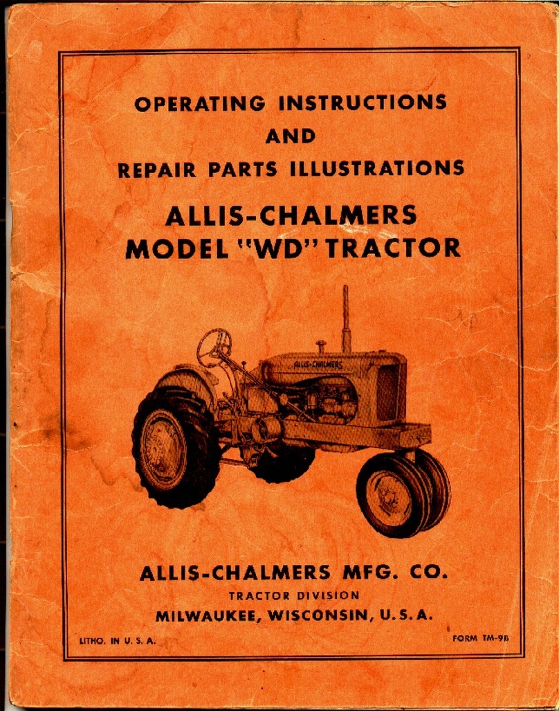
Allis-Chalmers
Allis-Chalmers WD Use and care manual
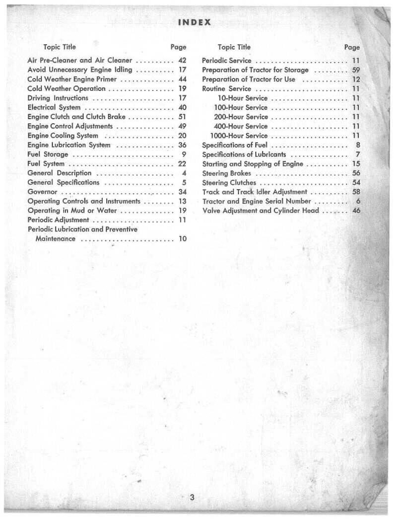
Allis-Chalmers
Allis-Chalmers HD 6B User manual
Allis-Chalmers
Allis-Chalmers ac130 series User manual
Allis-Chalmers
Allis-Chalmers HD-14 User manual
Allis-Chalmers
Allis-Chalmers 910-6 Speed User manual
Allis-Chalmers
Allis-Chalmers H 4 Specifications
Allis-Chalmers
Allis-Chalmers HD-9 User manual
Allis-Chalmers
Allis-Chalmers 10 hp User manual
Allis-Chalmers
Allis-Chalmers Simplicity 9523 Instruction Manual
