Allis-Chalmers HD-5 User manual

FOREWORD
This
manual
is
prepared
to'
provide the customer
and
the organiza-
tion personnel with complete information
and
instructions on the
maintenance
of
the Model
HD-5
Trador.
Extreme care has been
exercised
in
the designing, seledion of malerials and the assembly
of
the traefor. By proper maintenance
and
skillful operation
of
the
tractor, the utmost satisfaction in performance
and
service can
be
obtained.
In
order
to
become familiar with the various parts
~f
the tractor, it
is
urged that the mechanic study the instructions
in
the manual
and
use
it as a reference when performing repair
or
maintenance operations.
All information
and
illustrations shown throughout this manual are of
the "Standard
JJ
Model
HD-5B
Trador,
unless otherwise stated.
Where
special tools are required, their application and use are
illus-
trated.
Sections I through
XIX
contain a detailed description
of
the various
assemblies of the tractor and instructions
for
the proper ad;ustment
and
repair
or
rebuilding
of
these assemblies.
Section XX describes the Special Equipment available
for
the tractor
and
outlines the service on these parts.
General Maintenance Instructions are given
in
Section
XXI,
and
Fits
and
Tolerances in Section
XXI/.
Trouble Shooting Information given
in
Section
XXIII
will aid in deter-
mining the cause
of
operating irregularities that
may
occur and indi-
cates what
may
be done to correct them.
To
obtain the best results
and
to maintain the original quality built
into the tractor,
it
is
important that genuine Allis-Chalmers Parts
be
used when new parts are required.
IMPORT
ANT: Always furnish the dealer with both the Tractor
and
Engine Serial Numbers when ordering parts.
Many Allis-Chalmers owners employ the Dealer's Service Department
for all work other than routine care
and
adjustment.
This
practice
is
encouraged as our dealers are
kept
well informed
by
the factory
regarding advanced methods
of
servicing Allis-Chalmers products
and
are
equipped
to render satisfactory service.
1

2

SUBJECT
INDEX
SUBJECT
Page
SEC
TIO)'!
Description
and
Specifications 5
Fuel System -Engine
11
Air Intake System -Engine 36 !
Cooling System -Engine
55
. . I
-
Lubrlcatmg System Engine 64
Governor
and
Governor Controls
71
,
Electrical System 78
Instruments
88
Engine 90
Engine Clutch
and
Clutch Broke 130
Transmission
and
Bevel
Gear
136
Steering Clutches
150
Steering Brakes
155
Final Drives
158
Truck Frames
168
Draw Bar
179
Tracks
180
,
Main Frame
and
Equalizer Spring
183
Fenders
and
Seat
186
Special Equipment !
187
General
Maintenance Instructions ,
193
Fits
and
Tolerances 197
Trouble Shooting 203
3

4

SECTION I - DESCRIPTION AND SPECIFICATIONS
Topic Title
General
Description
...............
. Topic No.
1
General
Specifications
.............
. 2
Specifications of
lubricants
.........
. 3
Specifications of
Fuel
Oil
...........
. 4
Fuel
Storage
.....................
. 5
Tractor
and
Engine Serial Numbers
...
. 6
1.
GENERAL
DESCRIPTION
The description given herein
and
the
information
contained
in
this
manual
pertains only to the
Model
HD-5B
Tractor
(Standard
Model) unless
otherwise stated.
The model
HD-5B
Tractor
is
a
11,250
pound track-
type
tractor
powered
with a
54.6
horsepower, 2
cylinder, 2 cycle Diesel Engine. Power from the
engine
is
transmitted through a single
plate
over-
center
type
clutch
and
a universal joint drive shaft
assembly to
the
transmission. The final drive
gears
and
track drive sprockets
are
driven
by
two
multiple-disc steering clutches,
one
on
each
end
of
the
steering clutch cross shaft.
At
full
governed
engine
speed
(under load)
of
1800
R.P.M.
the transmission provides 5
forward
speeds,
ranging
from 1.46 M.P.H. to
5.47
M.P.H.,
and
a reverse speed of 1.99 M.P.H. Mechanical
self-energizing brakes insure
easy
and
positive
control of
the
tractor
at
all times.
The
tractor
is
equipped
with electric starter,
head
lights, full width crankcase
guard,
hinged
radiator
grille, front bumper,
and
positive seal truck
wheels,
track
idlers
and
track
support
rollers.
FUEL
ARM
"U>HIUN
REAR
FENDER
TRACK
RELEASE
HO,USING':r,..
ADJUSTING
SCR:EW..J
TRACK
RELEASE
v,"","-,
TRACK
IDLER
SHOE
FRAME
HEADLIGHT
CRANKCASE
GUARD
'_
______________
Fig. I
-Model
HD-58
Tractor
______________
-'
5
II

2.
GENERAL SPECIFICATIONS (STANDARD TRACTOR)
GENERAL:
Weight
(60"
tread)
.....................•....................
Overall
length
..................•..........................
Overall Width (60" tread)
...................................
.
Overall Height (including air pre-cleaner
and
exhaust pipe)
........•
(Air pre-cleaner
and
exhaust pipe removed)
....
, . ,
............
.
Tread Width -
Wid.
Tread
.....•..............•..............
Turning Radius
(60"
tread)
.....•
, . , , , ,
.............
,
....•.
, ,
..
length
01
Track on Ground
..................................
'
Track Shoe Width
(Standard)
..............................•..
Ground Contact Area
(~tandard
Shoe)
........•.••..............
Ground Pressvre (6011
tread)
............
, ,
...
,
...•..•.
,
......
.
Ground
Clearance
........
, , ,
............
, . , . ,
......
,
......
.
Drawbar
Height
.....•......................................
Lateral Movement
of
Drawbor
.........
,
....
, . ,
..•......
, ,
....
.
MAXIMUM
SPEEDS:
lst
Gear
.................................................
.
2nd
Gear
................................................
.
3rd
Gear
....................•.•.•........................
4th
Gear
........•.•.........................•••....•••....
5th
Gear
.................................................
.
Reverse
•••••.
,
•......•.•.
,
......•.......
,
......•..••.•••••
ENGINE:
Make
............•......•...........•..........•••.•..••••
Type
..........................................•••....•.•.
Number
of
Cylinders
.......................................
.
Bore
and
Stroke
.,.
, ,
.•........•............•.•......
, ,
....
.
Piston Displacement
.,
........
"
.................•....
,
.•...•
Full
Governed
Speed
(under load)
.............................
.
Maximum Net
Torque.
,
............................
,
........
.
Drawbar Horsepower
(at
rated
speed of 2.44 M.P.H.)
.............
.
Belt Horsepower
•............
,
......................•.
,
....
.
Fuel Used
....•....................................•••....•
Fuel injection System
......•......
: . . •. • . • • . . . . . . . . . . . .
..
.
..
Lubricotion
..••••
,
.........
"
..•.........
,.".,.,
..•.......
11,250 Ib,.
10 ft. 4% in.
6
ft.
6l-!>
in.
6 ft. 1
Y.
in.
5 ft. %
in.
60
in.
6
It.
10%
in.
5 ft. 4\4 in.
131n.
1670'h sq.
in.
6.73 Ib,.
per
sq. in.
1110\
in.
13·15/16 in.
21
in.
1.46
M.P.H.
2.44
M.P.H.
3.30 M.P.H.
3.96 M.P.H.
5.47 M.P.H.
1.99 M.P.H.
General
Motors Diesel
2.Cycle
2
4%
x 5
in.
142 cu. in.
1800
R.P.M.
179.1 ft. lb. @ 1270
R.P.M.
43.S
51.9
No.1
and
2 Dle,.1
Unit
Injectors
Forced Feed
CAPACITIES
(Fuel, Oil
and
Coolant-
U.
S.
Standard
Measure):
Fuel Tank
....................................••.......••..
Cooling System
......•.•................................•.••
Engine Crankcase . ,
.....
,
..............
, . , . ,
......
,
........
.
Transmission
..............................................
.
Final Drives (each)
.........................................
.
Air
Cleaner
•..........
,
....
,
.......................•....•..
Approximate
Capacity
37
Gollons
3%
Gallons
2 Gallons
5 Gallon,
3 Gallons
2'1.!
Quarts
The
Allis·Chalmers Manufacturing Company reserves the right to
make
changes
in
the
above
specifications
or
to
add
improvements
at
any
time without notice
or
obligation.
6

3.
SPECIFICATIONS
OF
LUBRICANTS
A.
Engine
Crankcase
Lubricant.
USE
NON-CORROSIVE
DIESEL
ENGINE
LUBRI-
CATING
OIL
CONTAINING
ADDITIVES
WHICH
WILL
PREVENT
SLUDGE
OR GUM DEPOSITS.
UNDER
NO
CIRCUMSTANCES SHOULD A COR-
ROSIVE
DIESEL
ENGINE
LUBRICATING
OIL
EVER
BE
USED.
Atmospheric
Tel)1peroture Viscosity
Above
32°
F.
Use
SAE
30
0°
F.
to
32°
F.
Use
SAE
20
0°
F.
and
below
Use
SAE
10
Manufacturers
of lubricants
recognize
the
impor-
tance
of
the
qualities
required
for use
in
our
equip-
ment
and
they
are
co-operating
fully
to
insure
the
use
of
only those oils which fulflll these require-
ments. The oil distributor
and
oil
manufacturer
are
to
be
held responsible for
the
results
obtained
from their products.
The
outstanding
lubricating
requirements
for effi-
cient
operation
of
this
engine
are:
The
maintaining
of
piston rings
in
a
clean,
free
condition;
absence
of
hard
carbon
and
"varnish"
deposits
on
or
within
engine
parts;
the
prevention
of
bearing
corrosion
and
the
promotion of
general
cleanliness within
the
engine.
Proper
operation
and
maintenance
of
the
engine
is
necessary
to
obtain
the
desired
results from
the
lubricating oil.
Operating
and
maintenance
fac-
tors
can
be
effectively controlled by
the
engine
user.
B.
Transmission
and
Final
Drive
Lubricant.
Lubricate these assemblies with
engine
oil. A list
of
the
various
brands
of
engine
oils which
have
7
been
tested
and
found satisfactory for use
in
these
assemblies
is
shipped
with
each
tractor
and
is
also
available
from Allis-Chalmers
dealers.
Use
only
an
oil shown on this list,
as
the
use of untested
oils
may
result
in
deterioration
of
the
Neoprene
boots
and
rings
in
these assemblies.
Use
oils with
the
following viscosity:
Atmospheric
Temperature
Viscasity
Abave
32°
F.
Use
SAE
50
32°
F.
and
below Use
SAE
30
C.
Truck
Wheel,
Track
Idler
and
Track
Support
Roller
Lubricant.
Lubricate these assemblies with a
grease
that
has
been
tested
and
found satisfactory by Allis-
Chalmers
Manufacturing
Company.
The
type
of
grease
used for lubricating
these
assemblies
was
selected
because
of
its
good
pumpability
and
cold
temperature
characteristics
and
because
of
its havir.g a minimum effect on
the
synthetic
rubber
seal
boots.
It
is
also
an
extremely
stable
grease
and
will not
deteriorate
excessively
with long use.
A revised list of
approved
oils
and
greases
is
issued
every
six months
and
new oils
and
greases
which
have
been
tested
and
approved
during
each
period
are
added
to
the
list. Ask
your
nearest
Allis-
Chalmers
factory
branch
or
authorized
dealer
for
the
latest
list.
D.
Pressure
Gun
Lubricant.
Use a pressure
gun
lubricant
with a minimum
melting point
of
300°
F.
This lubricant should
be
in
a viscosity
range
so
as
to insure
easy
handling
in
the
pressure
gun
at
prevailing
air
temperatures.

4.
SPECIFICATIONS
OF
FUEL
OIL
Use
No.1
Diesel
Fuel
Oil purchased from a reputa-
ble
oil
company.
In
worm weather,
No.2
Diesel
Fuel Oil may be used.
This
fuel must
be
within the
classification limits
as
established by the American
Society for Testing Material. Tentative Diesel Fuel
Oil Specifications
(ASTM
- D975).
For commercially satisfactory engine life
and
per-
formance, fuel
oil
requirements must comply with
four basic qualifications:
1. Physical cleanliness.
2. Absence of Chemical contamination.
3. Proper burning characteristics.
4. Cold starting ability.
Physical cleanliness means freedom from water,
dirt
and
other incombustible ingredients. Since all
present
day
high
speed
engine fuels
ore
completely
distilled, they leave the refinery
in
clean condition.
Transport
and
subsequent storage account for the
addition of most foreign matter found in the fuel.
Proper burning characteristics
are
dependent
upon
ignition quality
and
volatility.
The
fuel should have a cetone number of
at
least
40,
and
should
be
free from alkali,
odds,
gum,
and
water.
The
sulphur content should not exceed
0.5%
for summer operation
and
0.3%
for winter
operation. Fuel oils having these specifications
are
available from most
oil
companies.
The
use
of
fuels
having more than the specified sulphur con-
tent
are
conducive to harmful engine deposits,
rapid wear,
and
sticking rings and valves.
Volotility
is
determined by the boiling temperature
range. Fuels having a
low
final boiling point will
vaporize
ClOd
burn more completely than fuels with
a high final boiling point.
The
preferred high speed diesel fuels
range
in
color from white to light amber.
5.
FUEL
STORAGE
------
______
Fig. 2 -
Fuel
Storage
rank
The importance
of
proper
storage
of fuel cannot
be
too strongly stressed.
Storage
tonks, drums
or
8
service tanks must
be
free from rust, scale, sedi-
ment or
any
other foreign matter which
will
con-

taminate the fuel,
dog
the fllters
and
eventually
damage
the fuel pump
and
iniectors.
A portable storage tank provides the best method
for storing fuel on the job.
In
a tank, the sediment
and
water can easily be drained
and
the fuel
can
be pumped into the tractor fuel tank with a mini·
mum
of handling. Consult your local Allis·
Chalmers
dealer
for details
about
this type of
storage
tank. Since condensation
will
occur
in
the
tank,
it
is
very important
that
a sediment sump be
provided
in
the bottom of the storage tank where
the
water
and
settlings
can
be
drained daily.
Fuel
should be allowed to settle
at
least
4B
hours
in
the
storage
container before
it
is
put
in
the fuel
tank of the tractor.
It
is
advisable to use a pump
and
draw
the fuel from the tank or barrel rather
than from the bottom of the container by means
of a faucet
or
through the bung hole.
Where conditions
are
such
that
drums must be
used to supply fuel,
it
is
advisable to have enough
drums to allow sufficient time for the fuel to settle.
The fuel should
be
used only to within
about
three
inches from the bottom.
The
fuel thus left
in
a
number of drums can be collected into one drum
and
used after the usual time allowed for settling.
In
this manner, the sediment
and
foreign matter
will
be disposed of
and
no
fuel
will
be wasted.
Whenever drums
are
used for storage, they should
be
covered or placed under shelter to avoid the
fuel becoming contaminated by water which
will
enter through the flller plugs when
it
rains, even
though the plugs
are
tight.
The fuel tank of the tractor should be fllled
at
the
end of the day's run rather than
in
the morning.
This
will
reduce the water content, as a
full
tank
is
less
subject to condensation. The fuel tank
is
provided with a drain elbow
and
drain cock.
Sediment
will
settle into this elbow
and
can be
drained.
6.
TRACTOR
AND
ENGINE
SERIAL
NUMBERS
9
On all parts orders
and
in
all correspondence
relative to the tractor,
it
is
necessary that both
tractor
and
engine serial numbers be given.
This
will
properly identify the particular tractor
and
will
insure obtaining the correct replacement parts
for it.
Prior to engine Serial Number 2·71·111
BO,
the
engine serial number
is
stamped on a plate
at-
tached to the left side of the cylinder block below
the governor control housing. On engines Serial
Number 2·71·11180 to 2·71-15635 the number
is
stamped directly
in
the cylinder block
in
the same
relative location. Effective on engines after
2-71-15635 the engine serial numbering system
was changed.
In
the new system of numbering,
the preflx numbers
2-71
were changed to
read
2A-l, 2A-2, etc.,
and
are
stamped
in
the cylinder
block.

10
The
tractor
serial number
is
stamped
in
the
rear
face of the steering clutch housing
near
the
upper
right corner.

..
1
::e
I
~
~
-
::a
U
!


SECTiON
II
-ENGINE
FUEL
SYSTEM
Topic Title
Description of System
..............
.
Checking
Fuel
Supply System
........
.
Fuel Tank
and
Drain Elbow
.........
.
Fuel Filters
....•..................
Fuel Pump
...............
,
......
.
fuel Pump Drive
..•................
Fuel Iniectors
....................
.
Injector
Copper
Tubes
.............
.
Fuel Manifolds
...................
.
Topic No.
1
2
3
4
5
6
7
a
9
1.
DESCRIPTION OF SYSTEM
The engine fuel system consists of the fuel tank,
first stage fuel filter, fuel pump,
seCOl)d
stage
fuel
filter, iniectors
and
fuel lines.
The
fuel
is
drawn
from the bottom
of
the tank
and
through the first
stage
filter
by
the fuel pump.
The
pump circulates
the
fuel under pressure through the second
stage
fuel filter
and
inlet fuel manifold
in
Ihe cylinder
head,
and
Ihrough
the
inieclors.
As
the
fuel enlers
each injeclor, it passes through a small porous
metal filter
in
the iniector body. The amount
of
fuel required by the engine
is
injected into
the
cylinders by the injectors. Surplus fuel not required
for combustion, leaves each iniector through a
second porous melal filter, enters the relurn fuel
manifold
in
the cylinder
head
and
relurns
to
the
fuel tank. A pressure
of
25
to 45 pounds
is
main-
lained within the system by a restricted fitting
located
at
the cylinder
head
return manifold
open-
ing.
The
continuaus circulation
of
the fuel through
fhe injectors helps to cool them
and
eliminates the
possibility of air pockets
in
the fuel supply system.
fUEL
TANK
SED
JMENT
SUMP,~;;c;;:::;:::::;;=:;:;:;;rI!---.J
DRAIN COCK
fUEL
LINE
VALVE
INJECTOR FUE.L LINES",
RETURN
FUEL PASSAGE
, .
~INJECTORS
RESTR1CTED FITTING
RETURN TO TANK
N~.~!:'.
':hi
B!~i
I!
;:
c~;:--o
2ND
STAGE
FUEL
FlL
TER----.
\
(~
\. / I i
'U
~I;
V'I
II
~j
.,
"
1ST
STAGE
FUEL
F;~
TE:
\
FUEL
NLET
fUEL
PASSAGE
PUMP
1---
__________
Fig.
I-Schematic
Fuel
Flow
Diagram
-------------'
11

2.
CHECKING
fUEL
SUPPLY
SYSTEM
A.
General.
Under normal conditions with
the
engine operating
at
full
throttle,
25
to 45 pounds pressure
will
be
indicated on the fuel pressure
gauge,
if
the
tractor
is
equipped
with a
gouge.
If the tractor
is
not
equipped
with a fuel pressure
gauge,
and
condi-
tions occur which indicate incorrect fuel pressure,
the
pressure can
be
checked by installing a
gouge
in the delivery line
of
the fuel pump
at
any
point
between the pump
and
the inlet manifold opening.
Fuel pressure below normal, uneven running of the
engine, excessive vibration, stalling when idling,
and
a loss of power
are
indications of insufficient
fuel supply to the injectors.
To
determine
the
couse for the
above
conditions
check for the following:
Air
being drown into system
Clogged fuel filter elements
and
fuel lines
Clogged injector fuel filters
Inoperative fuel pump
To
check the flow of fuel through the system, dis-
connect the fuel return line
at
any
point between
the
fuel return manifold
and
the fuel tonk. With
the engine operating
at
full
throttle, the system
will
be
functioning properly when a
full
stream of
fuel with considerable force can
be
observed re-
turning to the fuel tonk through the fuel return
line.
If
only a small stream
is
observed returning
to
the tank, all
the
causes listed
above
must
be
checked
and
eliminated
in
turn.
B.
Check
for
Admission
of
Air
Into
System
and
for
Clogged Filter Elements
and
Fuel Lines.
To
check for
air
being admitted into the system,
remove the va
Ive
rocker arm cover
and
loosen
or
disconnect
one
of the injector fuel lines, then start
the engine.
If
air
is
entering the fuel system, foam
or
bubbles
will
be
observed
in
the fuel
that
emerges
from the loosened connection. Correct this condi-
lion by tightening
any
loose fuel lines
and
filter
connections between the fuel pump
and
the fuel
tonk. Test for smooth operation
and
full
flow
of
fuel.
If
the fuel lines
or
filters
are
dogged
remove the
fuel lines,
dean
both filter shells
and
install new
12
elements.
Blowout
the
lines while they
are
dis-
connected.
This
should eliminate the difficulty.
Check for
full
flow of fuel
after
engine
is
again
started.
C.
Check
for
Clogged
Injector
Filters.
If
the
engine
still
runs
"ragged"
with suitable fuel
return, the injector filters for one
Or
both cylinders
may
be
partially
dogged.
Locate the faulty injec-
tor as follows:
1.
Run
the engine
at
idling speed
and
cut out
each injector
in
turn by holding the injector
follower down with a screwdriver
or
small
block of wood while the engine
is
running,
as illustrated
in
Figure
No.2.
CAUTION,
Do
not allow the screwdriver to slip olf
the follower
as
damage
to the valve assemblies
con easily result.
If
the engine speed decreases
when the follower
is
held down
it
will
indicate
that
the injector for
that
cylinder
is
functioning properly.
If
the engine continues to run with no decrease in
speed, the injector
is
inoperative
and
should
be
removed for further inspection.
2. Stop
the
engine
and
remove the fuel feed line
that connects the injector
to
the return fuel
manifold. Hold a finger over the injector fuel
outlet
and
crank the engine with the starter.
If
the fuel gushes from the injector while the
starter
is
cranking the engine,
on
ample fuel
supply
is
indicated. Remoye the injector
and

check for clogged injector filters. Refer to
"INJECTOR
REMOVAL"
in
this section.
D. Check
for
Inoperative
Pump.
Assuming
that
there
is
a sufficient supply of fuel
in
the
fuel tank,
ond
that
the fuel
is
reaching the fuel
pump, remove the pipe plug from the
top
of the
second stage fuel filter. With the engine running
the
fuel
will
gush from the opening
in
the filter.
If
it
does not,
the
fuel pump
will
be
considered
inoperative
and
must
be
removed
and
repaired or
replaced.
E.
Excessively High Pressure.
A relief valve
is
installed
in
the fuel pump
to
pre-
vent high fuel pressure. When the relief valve sticks,
high pressure
will
develop
and
will
be
indicated
on the fuel pressure
gauge,
if
the tractor
is
equipped with a fuel pressure
gauge.
When high pressure occurs, the valve
in
the fuel
pump should
be
inspected
and
the
cause
deter-
mined for
its
sticking. The second
stage
fuel filter,
the restricted fitting
in
the fuel return line
at
the
return manifold
and
all fuel lines should
be
in-
spected for clogged passages.
Continued operation with excessively high pres-
sure (over
60
pounds) may result
in
damage
to
the
fuel system.
3.
FUEL
TANK
AND
DRAIN ELBOW
A. Description.
The fuel tank, located
at
the
rear
of
the tractor has
a capacity of approximately
37
gallons.
The drain elbow on
the
bottom
of
the fuel tank
provides a means of flushing the tank
and
also acts
as
a sediment sump.
Open
the drain cock on this
elbow before the engine
is
started
at
the beginning
of the day's operation
in
warm
weather
or
shortly
after the end of the
day's
operation
in
freezing
weather. Close the cock when clean fuel runs out.
Drain the tank, when
an
accumulation of rust
and
scale
is
evident,
by
removing the plug
in
the end
of the drain elbow, then flush the tank thoroughly.
B.
Maintenance.
If
a large accumulation of rust
or
scale
in
the tank
13
becomes
apparent,
remove the drain elbow
and
the fuel lines from the bottom of the tank
and
flush
the tank with clean fuel
or
clean the tank with live
steam.
This
will
prevent frequent clogging of the
fuel filters
and
will
eliminate possible trouble
in
the fuel system.
C.
Removal.
When
it
becomes necessary to remove the fuel
tank, proceed
as
follows:
1.
Remove the arm cushions from the top of
each
battery
box
and
remove the capscrews
used
in
fastening each battery box to
the
fuel tank.
2. Remove
the
bolts attaching the tank to
the
rear
fenders.
3. Close the fuel shut-off valve
at
the bottom
of
the tank
and
disconnect the fuel supply line
and
the fuel return line from
the
fuel tank.
4. Place a suitable chain or rope around the
fuel tank
and
remOve the tank from the trac-
lor. Protect all openings of
the
fuel tank
and
disconnected lines againsl the entrance
of
foreign material.

4.
FUEL
FILTERS
A. Description
of
First
Stage
Fuel Filter.
This filter, mounted
at
the
left side
of
the
engine,
contains a
replaceable
element. Dirt
and
sedi-
ment
in
the fuel
is
collected by this filter
and
pre-
vented from passing on
to
the fuel pump. A
drain
cock
in
the bottom
of
the filter shell allows
drainage
of
the sediment collected.
t_----COvER
SCREW
O,.·-----GASKET
~---C:OVER
,\-+---COVER
GASKET
~-4
__
---SPRING
<CIJ";_'
-----
WASHER
e'"'"'----GASKET
i"----
ELEMENT
_--SHELL
~
___
-DRAIN
COCK
-fir.t
Stage
fuel
filter
-----'
B.
Service
of
First
Stage
Fuel
Filter.
Open
the filter
drain
cock
daily,
before
the
en-
gine
is
started
at
the
beginning
of
the
day's
opera-
tion in
warm
weather
or
shortly
after
the
end
of
the
day's
operation
in
freezing
weather,
and
allow
the
water
or sediment to
drain.
Close the
drain
cock
when
clean fuel runs out. Remove
and
dis-
card
the
old
element
and
install a new
one
after
every
300
to
500
hours of
operation
(more often
if
conditions
warrant)
or
when
the filter becomes
clogged.
A
clogged
filter
is
usually
indicated
by
irregular
engine
performance.
To
change
the element, remove the filter cover,
drain
the filter, lilt out the spring
and
element
and
wash the inside of the filter shell. Place a
new
element
and
the spring
in
position
and
re-instali
the
cover, using the new cover
gasket
furnished
with the new element.
Start
the
engine
and
check
to
be
sure
that
the filter
does
not
leak.
C. Description
of
Second
Stage
Fuel
Filter.
This
filter, mounted on
the
right side
of
the
engine,
contains a
replaceable
element. Any small
par-
ticles
of
dirt, which may
have
passed
through
the
first
stage
filter
are
collected by this filter
and
prevented
from reaching
the
injectors. A
drain
cock,
in
the bottom
of
the filter shell, allows for
drainage
of
the sediment collected.
f'"'"'----CAPSCREW
o
...
~
___
_
-GASKET
_--HEAD
c~
~GASKETS
_--ELEMENT
§l
~93:-'
----SPRING
i---SHELL
~...-_--DRAIN
COCK
L-
__
fig.
5-Second
Stage
fuel
filter---....l
14

D.
Service
of
Second
Stage
Fuel Filter.
Open the filter drain cock daily, before the engine
is
started
at
the beginning of the day's operation
in
warm weather or shortly
after
the end of the
day's operation
in
freezing weather,
and
allow
the
water
or sediment to drain. Close the drain
cock when clean fuel runs out. Remove
and
dis-
card
the old element
and
install a new
on'O
after
every
300
to
500
hours of operation (more often
if
conditions warrant) or when the filter becomes
dogged.
A
dogged
filter
is
usually indicated by
irregular engine performance.
To
change the element, drain the filter
and
re-
move the shell from the filter head. Remove
and
discard the old element. Wash the shell thor-
oughly. Install a new element.
NOTE:
The
spring
is
installed below the element
in
this
filter
and
above the element
in
the
first
stage filter.
Re-
install the shell, using the new gasket furnished
with the new element.
Start
the engine
and
check
to be sure
that
the filter does not leak.
5.
FUEL
PUMP
A.
Description.
The tractor may be equipped with either an
"Eaton" or a "Barnes"
Fuel
Pump, mounted to the
engine
as
shown
in
Figure
No.6.
The
"Eaton"
Fuel
Pump
is
a rotor type pump having
a delivery capacity of approximately
35
gallons
per hour
at
1000
R.P.M.
The pump
is
bolted to an
adapter,
and
is
driven by
an
adapter
shaft through
a hollow sleeve which acts os a universal joint.
The
adapter
shaft
is
driven by a helical
gear
on
the
balancer
shaft of the engine.
The pump rotates
in
a counter-clockwise direction,
viewed from the cover end.
The
four lobe inner
rotor rotates the outer rotor eccentrically when the
pump
is
in
operation to open
and
close the pas-
sages
in
the pump housing.
The
four lobe inner
rotor
is
attached to the pump shaft by a ball
lock
and
rotates the outer rotor which
is
free to turn
in
the pump housing cover.
As
the rotors revolve
in
the housing, fuel
is
displaced from the inlet
passage
to the outlet passage.
Two
pump shaft
oil
seals
are
used inside the body
at
the inner end. The sealing
edge
of
one
seal
faces the pump cover
and
retains the fuel within
the pump, the other faces the opposite direction
and
prevents engine lubricating
oil
from entering
the pump. The seals
are
located approximately
1/16"
apart.
A drain hole, located between the
two seals, vents to the atmosphere. A neoprene
g'asket fitted into the machined recess
in
the cover
is
compressed between the housing
and
the body
when the attaching bolts
are
drawn tight.
This
seal prevents fuel
oil
from leaking out
as
well
as
preventing air leaking inta the pump between the
15
cover
and
the housing.
A spring loaded relief valve, located on the inlet
side of the pump (right side of pump viewed from
cover end)
is
provided to by-pass fuel back to the
inlet side when the outlet pressure exceeds
37
to
47
P.S.1.
This
valve normally does not open since
its
purpose
is
to relieve excessive pump pressure
in
case of
dogging
in
any
of the fuel lines or
f1Iters.
The "Barnes" Fuel Pump
is
a constant flow
gear
type pump, having a delivery capacity
of
approx-
imately
35
gallons per hour
at
40
pounds pressure
and
1000
R.P
.M.
The
Barnes Pump
is
bolted to
an
adapter
and
is
driven
in
the same manner as
the Eaton Pump.
Two
steel gears revolve inside
the pump housing to create a vacuum
in
the intake
chamber, thus drawing fuel from the fuel tank.
The
fuel
is
carried around the gears
in
the spaces
between the teeth,
and
is
forced out of the pump
under pressure.
The
driving
gear
is
mounted on a free-floating type
drive shaft
and
is
keyed fo the shaft by a shear pin.
The
driven
gear
is
supported
in
the bore of the
pump housing by
its
supporting journals which
are
an
integral
part
of the driven
gear.
Two
pump shaft ail seals
are
used inside the stator
at
the inner end. The sealing
edge
of one seal
faces the pump housing
and
retains the fuel within
the pump, the other faces the mounting flange end
of the stator,
and
prevents engine lubricating ail
from entering the pump. The seals
are
located
approximately
1/16"
apart.
A drain hole, located
between the two seals, vents to the atmosphere.
A spring loaded relief valve, located
on
the inlet

side of the pump (right side of pump viewed from
cover end)
is
provided to by-pass fuel back to the
inlet side when the outlet pressure exceeds
47
10
60
P.S.I.
This
valve normally does nol open since
its
purpose
is
10 relieve excessive pump pressure
in
case clogging occurs
in
any
of the fuel lines or
filters.
B.
Service.
If
the fuel pump
is
removed for reconditioning, the
pump drive assembly should also be removed for
inspection.
p..:J:JCf\l\t)lY
C.
Removal
of
Fuel Pump
and
Pump Drive
Shaft
Assembly.
1. Disconnect Ihe fuel lines from Ihe pump.
2. Remove the nuts attaching Ihe fuel pump
and
drive
ada
pier 10 Ihe engine block.
3.
Pull
the pump off the attaching studs
and
remove Ihe square, lubular fuel pump cou-
pling.
4. Remove the flat
head
capscrew attaching
Ihe drive
adapter
10 the engine block
if
cap-
screw
is
used for altaching.
NOTE:
A flat
head capscrew
is
used to hold the
adapter
assembly
in
place on the early model engines,
and
a dowel
is
used on the later model en-
gines.
5. Tap the drive
adapter
flange lightly to loosen
and
withdraw it from the engine block.
D.
Disassembly
of
"Eaton" Fuel Pump.
The relief valve assembly may be removed from
the pump body without disassembly of the other
parts of the pump, by removing the fuel pump plug
and
jarring the valve parts from the body.
ROTOR
(OUTER)
\
PLUG
STEE\
BAllBUSHINGG\
j,
~
~
1.
C)
'/HI~~l
(INNER)
SH~
<{'
Q9
Ill-
~
SPRING;j{
\
GASK~
.,
./
.....
\
VALVE
.
"\
PLUG
GASKET
BODY
ASSEMBLY
SEAL
(OUTER)
GASKET
ROTOR
(INNER)
L---
_________
.!ig.
7
-"Eaton"
Fuel
Pump Details:
____________
.....J
16

When removing the relief valve assembly, note the
position of each
part
so that the parts may be
reassembled
in
their same relative position.
If
the relief valve only
is
to be inspected,
no
further
disassembly
is
necessary.
If
the entire pump
is
to
be dismantled proceed
as
follows:
1.
Remove the cover to body altachi
ng
bolts
and
install capscrews
1/4"
x 20 x
3"
long,
so
that the heads of the capscrews extend out
3/4"
from the pump cover.
2. Holding the pump assembly
in
hand,
tap
on
the heads of the capscrews with a soft ham-
mer,
separating
Ihe body
and
cover.
DO
NOT
PRY
BODY
AND
COVER
APART.
3. Remove the ouler rolor,
and
move the shaft
out toward the cover end of the pump, slide
the inner rolor forward on Ihe shaft
and
remove Ihe locking ball, Ihen remove Ihe
inner rotor from the rotor shaft.
4.
Remove the rotor shaft from the pump body
carefully, so as nat to
damage
the oil seals.
5. Drive the dowels from the pump body
if
necessary by means of a small punch
and
hammer.
6.
If
it
is
necessary to remove the seals, a tool
of the proper design may
be
used to
remOve
them
so
Ihey
will
nol be
damaged.
E.
Inspection
of
"Eaton"
Fuel
Pump
Parts.
1. Wash
alllhe
parts
in
clean fuel oil or solvent
and
inspect them carefully. The oil seals,
once removed from the pump, should
be
re-
placed.
If
the sealing
edges
of the seals
are
damaged
in
any
way,
so
that they do not
form a perfect seal around the shaft, either
a fuel
oil
leak or lubricating
011
leak
will
result.
2.
Inspect the rotors
and
the wearing surfaces
of the pump cover
and
body for
wear
and
scaring.
If
the rotors show excessive wear
or
are
scored they should be replaced.
If
the wearing surfaces
in
the pump cover
are
worn or scored, causing excessive looseness
of the rolors
in
Ihe cover
and
body, the pump
17
should be replaced.
3. Install the inner rotor on the pump shaft with
the locking boll
in
place.
If
excessive
wear
between these parts
is
found, new parts must
be installed.
4.
Check the
fit
of Ihe pump shaft
in
the pump
body bushings.
If
the shaft
and
bushings
show excessive wear they must
be
replaced.
The
specified diameter of the shaft
is
.4992"
and
the specified inside diameter of the
bushings
as
installed
is
.5015" making a
clearance of .0023" between the shaft
and
bushings.
5. Check the pump relief valve.
If
the valve
does
not form a light seal on
its
seat, lap the
valve using fine valve lapping compound.
A piece of wood
about
Ihe size of a pencil
makes a
good
holder for hand lapping.
CAUTION,
Use
only a small amount of com-
pound
50
that only the
seat
on the valve
and
in
the body
will
be affected. The ideal
seat
is
a ring about
1/64"
to
1/32"
wide
in
the
pump body. Thoroughly wa5h all Ihe lap-
ping compound
and
foreign material off the
valve
and
out of pump body.
6. Inspect the pump cover sealing gasket
and
the pump shaft seal gasket
and
replace
if
necessary.
F.
Assembly
of
"Eaton"
Fuel Pump_
1. Instal! Ihe bushings for the pump shaft
in
the
pump body
if
they were removed for replace-
ment, then, ream the inside diameter of the
bushings to .5015".
2. Install the pump shaft seal gasket
in
place
in
the pump body, then instal! pump shaft
inner seal with the sealing
edge
towards the
cover end of the pump. Make certain the
seal
is
instolled tight ogainst the seal gasket.
3. Install the pump shaft outer seol
with
the
sealing
edge
towards the mounting flange
end
of the pump.
4.
lubricate
the pump shaft end seals
and
in-
stall the shaft
in
the pump body. Install the
shaft from the cover end pushing it through
the bushings
and
then through the seals being

exceptionally careful not to
damage
the
seals.
Use
an
oil seal pilot tool on
the
drive
end
of
the
shaft
if
tool
is
available.
Before
inserting
the
shaft completely into position
in
the
pump body, install the inner rotor
and
locking ball on
the
shaft.
5. Install
the
outer
rotor
in
place on the inner
rotor.
6. Install the pump cover sealing
gasket
in
the
recess
of
the
pump cover, then place the pump
cover
in
position on
the
dowels
and
pump
body. Install the cover attaching bolts
and
tighten securely.
7. Turn
the
pump shaft
and
test it for bind.
The
shaft
should turn smoothly, with a slight
drag,
but should not bind
or
have
tight spots.
8. Install
the
relief valve parts,
make
certain
that
the
parts
are
installed properly
in
their re-
spective places on the inlet side of the pump
(right side when viewed from pump cover
end).
H'LJLJJING
9. Install the pump
body
plug
and
gasket
in
the
side opposite the relief valve.
10. Install the fuel pump on
the
engine
by direct
reversal of the removal procedure.
G.
Disassembly
of
"Barnes"
Fuel
Pump.
The relief valve assembly
may
be
removed from
the
pump
stator
without disassembly of
the
other
parts of the pump, by removing the pressure relief
spring plug
and
jarring
the
valve parts from
the
body.
When
removing
the
relief valve assembly, note
the
position of
each
part
so
that
the
parts
may
be
re-
assembled
in
their
same
relative position.
If
the relief valve only
is
to
be
inspected, no further
disassembly
is
necessary.
If
the
pump
is
to
be
dismantled proceed
as
follows:
1.
Remove the screws
attaching
the pump hous-
ing to
the
stator
and
install capscrews
1/4"
CAPS
CREW
DRIVING
GEAR
S
STATOR
FT
D
PLUG
SEAL
(INNER)
SEAL
(OUTER)
'--------------Fig.
a-"Barnes"
Fuel
Pump
Details
____________
....J
18
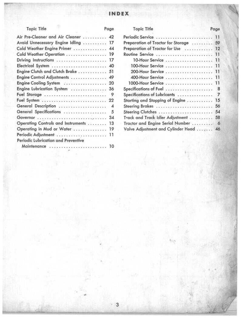
Table of contents
Other Allis-Chalmers Tractor manuals
Allis-Chalmers
Allis-Chalmers 10 hp User manual
Allis-Chalmers
Allis-Chalmers HD-14 User manual
Allis-Chalmers
Allis-Chalmers G User manual
Allis-Chalmers
Allis-Chalmers G User manual
Allis-Chalmers
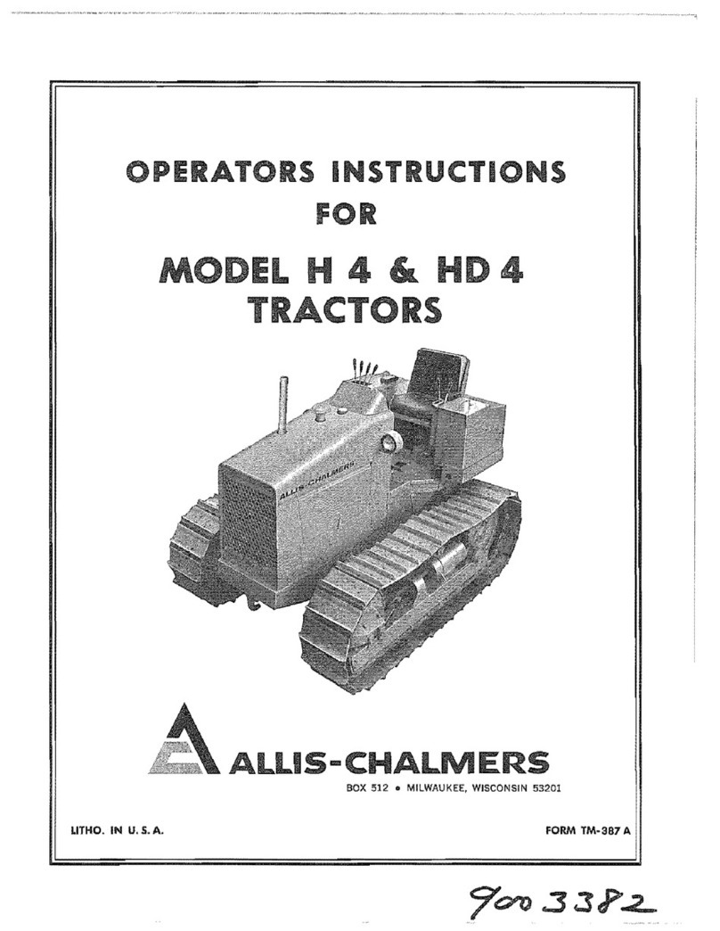
Allis-Chalmers H 4 Specifications
Allis-Chalmers
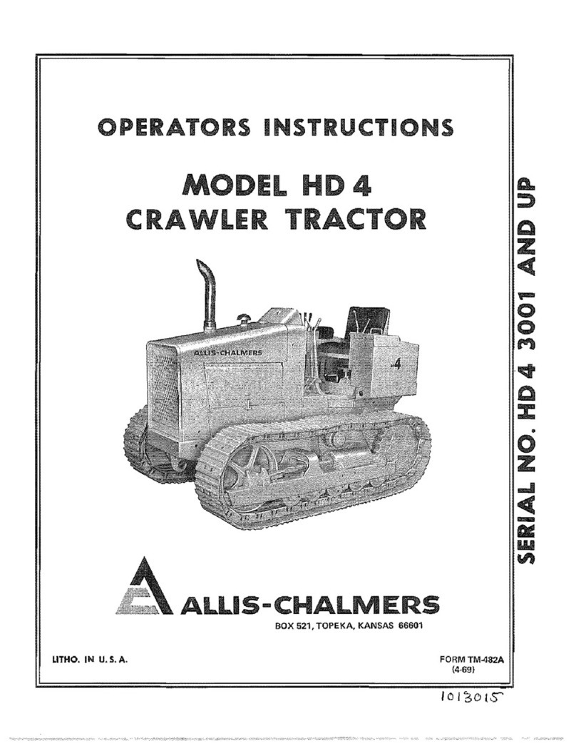
Allis-Chalmers HD-4 Specifications
Allis-Chalmers
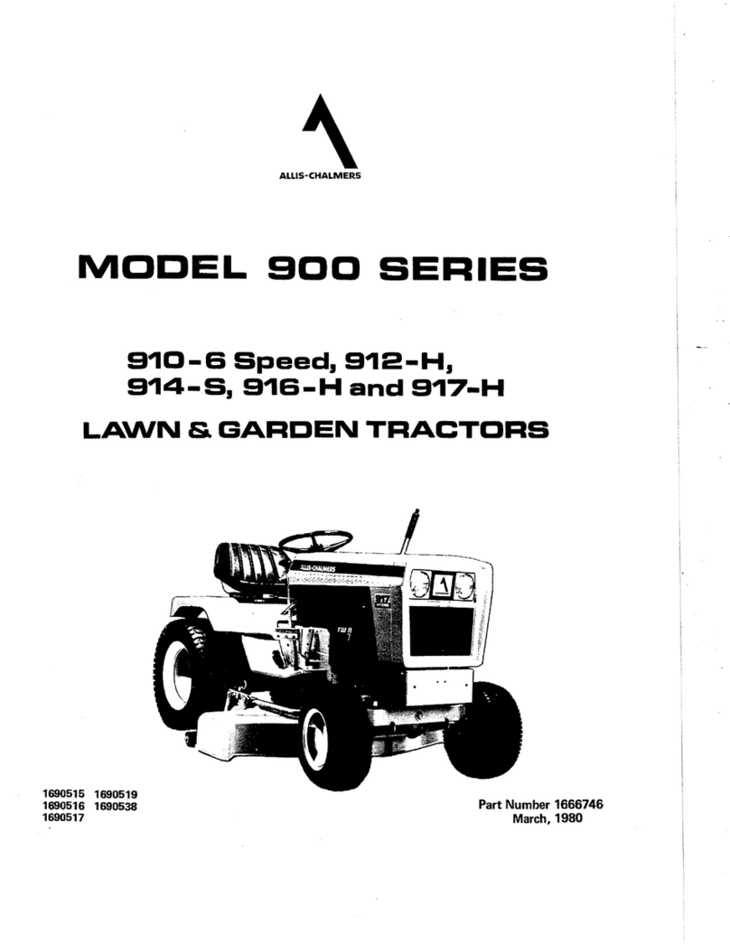
Allis-Chalmers 910-6 Speed User manual
Allis-Chalmers
Allis-Chalmers Simplicity 9523 Instruction Manual
Allis-Chalmers
Allis-Chalmers HD 6B User manual
Allis-Chalmers
Allis-Chalmers ac130 series User manual
