2
1
IMPORTANT SAFETY INSTRUCTIONS
WARNING
TO REDUCE THE RISK OF :INJURY
READ AND FOLLOW ALL INSTALLATION INSTRUCTIONS. DO NOT START INSTALLATION UNTIL
YOU HAVE READ AND UNDERSTAND THESE DIRECTIONS. IF THERE IS SOMETHING YOU DO NOT
UNDERSTAND, PLEASE CALL US.
NEVER let children operate or play with gate controls.
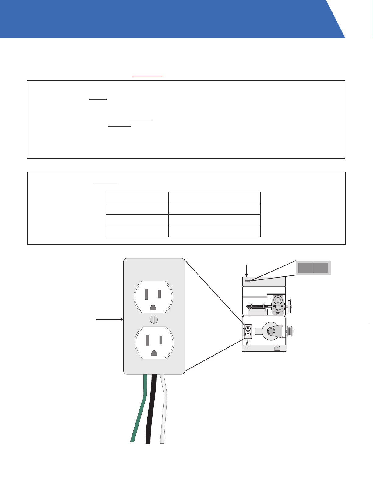
Locate the control station and make sure it is (a) within sight of the gate and (b) at a minimum height of 5
feet so small children cannot reach it.
Install the enclosed entrapment warning signs next to the control station and in a prominent location.
For operators equipped with a manual release, instruct the end user on the correct operation of the manual
release. Use the manual release only when the gate is not moving. It is advised that the power be turned
off.
Always keep people and objects away from the gate. No one should cross the path of a moving gate.
The gate operator must be tested monthly. The gate must reverse on contact with a rigid object, or stop
when an object activates the non-contact sensor(s). Always re-test the operator after adjusting the limits
and/or force. Failure to adjust and re-test the gate operator properly may cause severe injury or death.
Keep gate(s) properly maintained. Have a qualified service technician make repairs to gate hardware and
make proper adjustments to gate operator.
This gate entrance/exit is for vehicles only. Pedestrians must use a separate entrance.
There is nothing on a gate operator that is easily repaired or adjusted without a great deal of experience.
Call a qualified gate service technician who knows your gate operator.
SAVE THESE INSTRUCTIONS
IMPORTANT SAFETY INSTRUCTIONS
(CONTINUED)
BEFORE GATE OPERATOR INSTALLATION
ŸConfirm that the gate operator being installed is
appropriate for the application.
ŸConfirm that the gate is designed and built
according to the current published industry
standards.
ŸConfirm that all appropriate safety features and
safety accessory devices are being installed,
including all entrapment protection devices.
ŸMake sure that the gate opens and closes freely
(by hand) before installing the operator.
ŸRepair or replace worn or damaged gate
hardware before installing the gate operator.
ŸEliminate all gaps in the sliding gate below a 6
foot height that permits a 2 1/4” sphere to pass
through any location. This includes the area of
the adjacent fence covered when the gate is in
the open position
ŸEliminate all gaps in a swing gate below a 4 foot
height that permits a 4” sphere to pass through
any location. This includes the hinge area of the
gate.
GATE OPERATOR INSTALLATION
ŸOperator must be disconnected from the power
source before attempting any installation of
accessories.
ŸInstall gate operator according to the installation
instructions in this manual.
ŸAdjust the operator clutch or load sensing device
to the minimum force setting that will allow for
reliable gate operation.
ŸInstall the operator inside the fence line. Do not
install the operator on the public side of the fence
line.
ŸInstall a proper electrical ground to the gate
operator.
ŸControls intended for user activation must be
located at least 6 feet away from any moving part
of the gate, and where the user is prevented
from reaching over, under, around, or through
the gate to operate the controls.
ŸOutdoor or easily accessible controls shall have
a security feature to prevent unauthorized use.
ŸThe stop and/or reset button must be located in
the line of sight of the gate. Activation of the
operator reset control shall not cause the
operator to move.
ŸInstall a minimum of 2 warning signs, one on
each side of the gate where they are easily
visible.
ŸTake pictures of the installation.
ŸTest all safety features for proper function before
placing the automatic vehicular gate in
operation.
MAINTENANCE
ŸTrain owners/users on the basic functions and
safety features of the gate system, including
how to turn off the power and operate the
manual disconnect feature.
ŸLeave safety instructions, product literature,
installation manual, and maintenance manual
with the owner or end user.
ŸExplain to the owner or end user the importance
of routine service and operator testing on a
monthly basis.
INSTALL THE GATE OPERATOR ONLY WHEN YOU
HAVE READ THE FOLLOWING