ALLOMATIC SW-300DC User manual
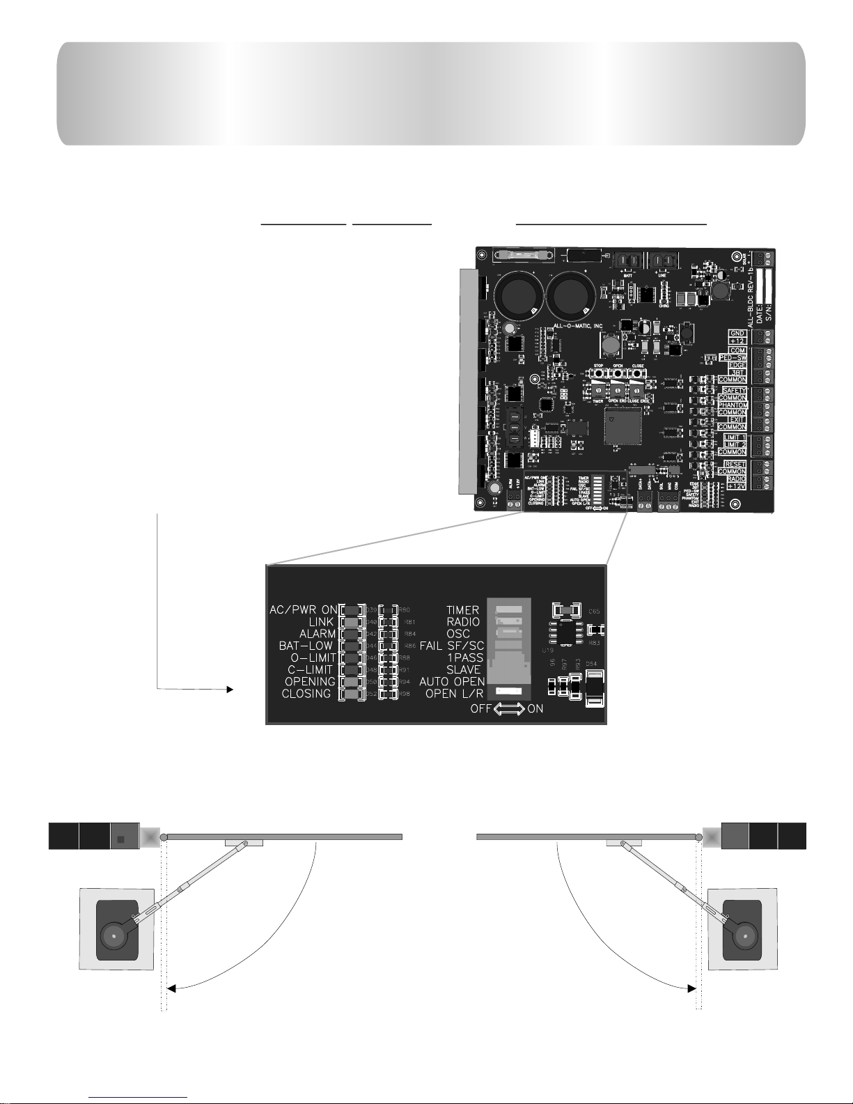
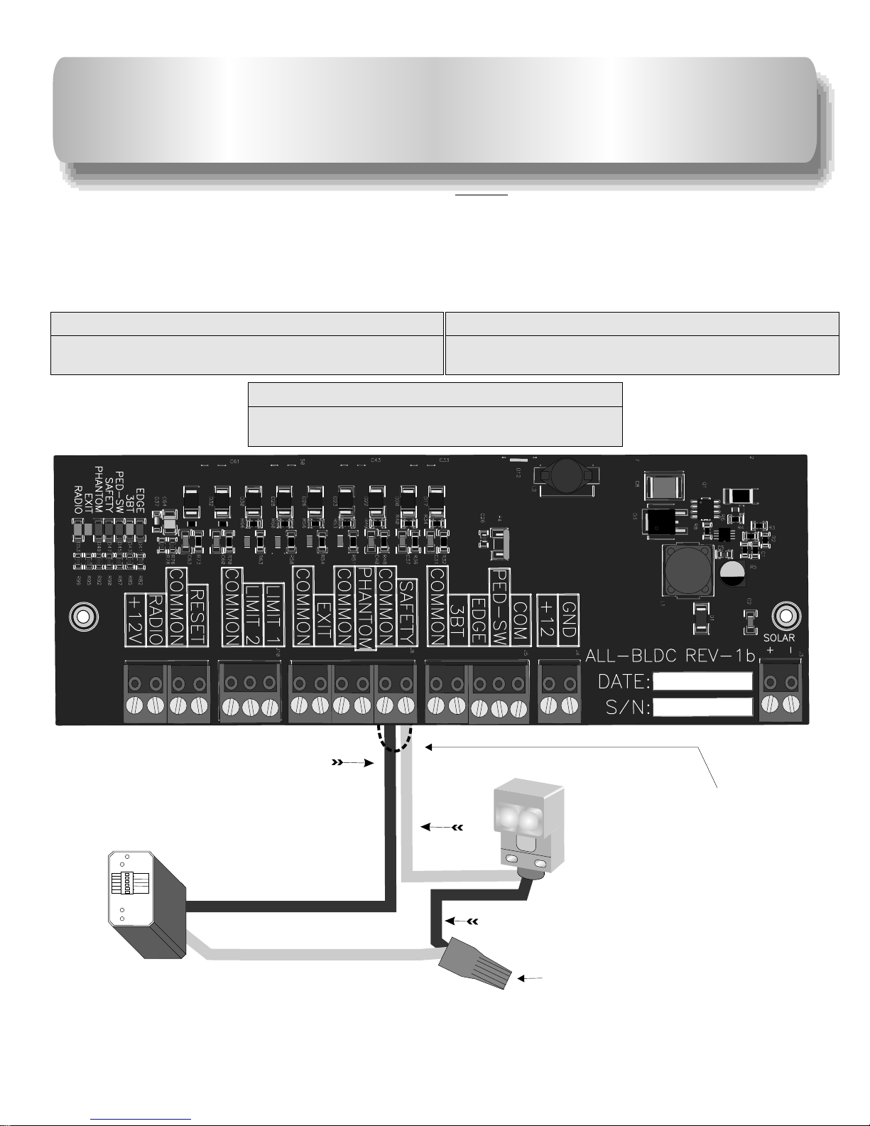
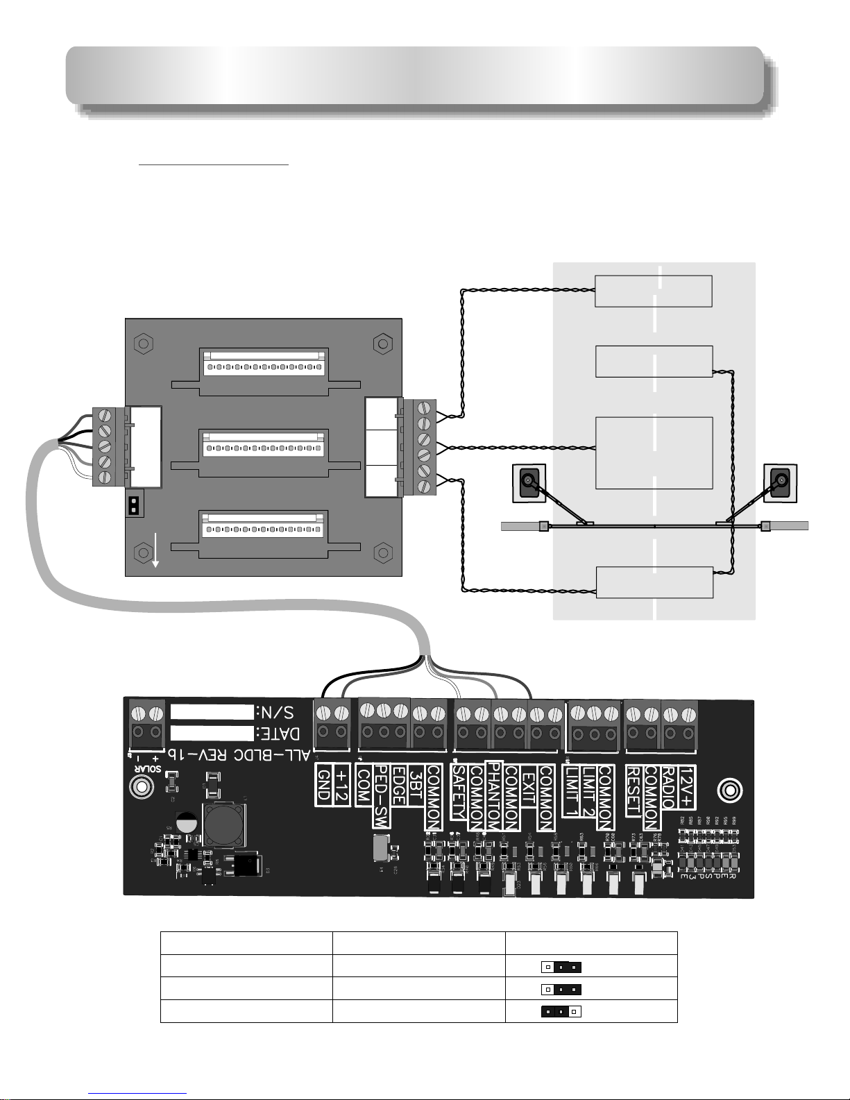
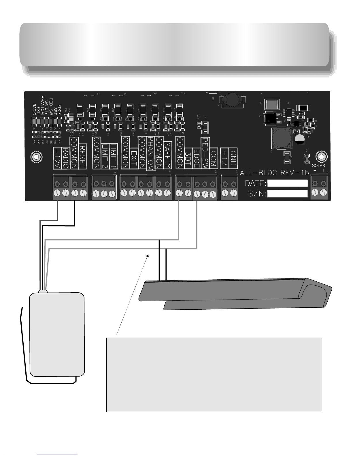
®
UL325
compliant
compliant
UL991
L
I
S
T
E
D
®
US
SW-300DC Installation Manual
Copyright © 2008 all-o-matic inc. www.allomatic.net
WWW.ALLOMATIC.NET
Pending

TABLE OF CONTENTS
Important safety instructions........................................................
Different UL 325 class types.............................................................
Concrete pad Specs.........................................................................
Operator & Arm Layout..............................................................
Compact Installation.........................................................................
Torque limiter & Arm adjustment......................................................
Gate travel adjustment.....................................................................
Directional settings..........................................................................
Electrical power connections...........................................................
Typical loop layout...........................................................................
General loop installation guidelines...............................................
Accessory connections...................................................................
Multiple safety device connections.................................................
Plugin detector installation..............................................................
Leading edge installation.................................................................
Three button station........................................................................
Master/Slave connections...............................................................
Magnetic/Solenoid lock installation.................................................
Radio receiver hookup....................................................................
Open & Close electronic reversing sensor(ERD) adjustment.........
Timer adjustment............................................................................
Dip switch functions........................................................................
Solar panel installation...................................................................
Swinger arm parts..........................................................................
2&3
4
5
6,7&8
9
10
11
12
13
14
15
16
17
18
19
20
21
22
23
24
25
26
27
28
1

IMPORTANT SAFETY INSTRUCTIONS
To reduce the risk of
WARNING
injury:
READ THE FOLLOWING DIRECTIONS. DO NOT EVEN THINK OF STARTING UNTILYOU HAVE
READ AND UNDERSTAND THESE DIRECTIONS. IF THERE IS SOMETHING YOU DO NOT
UNDERSTAND CALL US.
let children operate or play with gate controls. Keep the remote control away from children.
Always keep people and objects away from the gate. No one should cross the path of the moving gate.
This operator must be tested monthly. The gate must reverse on contact with a ridged object or stop
when an object activates the non-contact sensors. After adjusting the force or the limit travel, retest the
gate operator. Failure to adjust and retest the gate operator properly can increase the risk of injury.
Keep gates properly maintained. Have a qualified service person make repairs to gate hardware. It
takes many years of experience to make proper adjustments to gate hardware or operators.
There is nothing on a gate operator that is easily repaired without a great deal of experience. Save
yourself some time and call a qualified Gate Service Contractor who knows your type of gate operator.
Never
2

*Confirm that the gate operator being installed is appropriate for the application.
*Confirm that the gate is designed and built according to current published industry standards.
*Confirm that all appropriate safety features and safety accessory devices are being incorporated, including both primary and secondary
entrapment protection devices.
*Make sure that the gate works freely before installing the operator.
*Repair or service worn or damaged gate hardware before installation of the operator.
*Eliminate all gaps in a sliding gate below a 4 foot height that permits a 2 ¼ inch sphere to pass through any location, including the area
of the adjacent fence covered when the gate is in the open position.
*Eliminate all gaps in a swinging gate below a 4 foot height that permit a 4 inch sphere to pass through any location, including the hinge
area of the gate.
*Operator must be disconnected from the power source before attempting any installation of accessories.
*Install this gate operator according to our installation instructions.
*Adjust the operator clutch or load sensing device to the minimum force setting that will still allow for reliable gate operation.
*Install the operator inside the fence line(do not install the operator on the public side of fence line).
*Install a proper electrical ground to a gate operator.
*Install controls where users cannot touch or reach through the gate to operate the controls.
*Install all warning signs and take pictures of the installation.
*Test all safety features for proper function before placing the automatic vehicular gate into service.
*Train owner/users about basic functions and safety features of the gate system, including how to turn off the power and how to operate
the manual disconnect feature.
*Leave safety instructions, product literature, installation manual and maintenance manual with end user.
*Explain to the owner/user the importance of routine service and retesting on a monthly basis.
INSTALL THE GATE OPERATOR ONLY WHEN YOU HAVE READ THE
FOLLOWING:
3

Class one: Residential
A vehicle gate operator intended for use at a home of one to four single family dwellings, garages or parking area.
Class Two: Commercial or General Public Access
A vehicular gate operator intended for use at a commercial location or building such as a multi-family housing unit (five or more single
family units), hotel, garages, retail stores, other buildings servicing the general public.
Class three: Industrial or limited Access
A vehicular gate operator intended for use at an industrial location or building such as a factory, loading dock area, or other locations not
intended to service the general public.
Class Four: Restricted Access
A vehicular gate operator intended for use at a guarded industrial location or building such as airport security areas or other restricted
access locations not servicing the general public where unauthorized access is prevented via supervision by security personnel.
Other components required to satisfy UL 325
Each class must have a primary and secondary means to sense and react to obstructions within two seconds.
The six types of obstruction sensing systems are:
Type A:
Inherent obstruction sensing system. This system must sense and initiate the reverse of the gate within two seconds of contact with a
solid object.
Type B 1:
Provision for connection of a non-contact device can be used, such as a secondary protection.
Type B2:
Provision for connection of a contact sensor. Examples include an edge device or equivalent. This can be used for secondary protection.
Type C:
Inherent adjustable clutch or pressure relief valve.
Type D:
Provision for connection of or provided with and actuation device requiring continuous pressure.
Type E:
Inherent audio alarm.
All of All-O-Matic Inc’s Gate operators conform to the most ridged Class One.
DIFFERENT UL 325 CLASS TYPES
4

CONCRETE PAD FOR SW-300
24”
24”
24”
9.5”
13.5”
4”
OO
UU
RR
NN
33
88
66
BB
SS
33
1133
OO
UU
RR
NN
33
88
66
BB
SS
33
1133
OO
UU
RR
NN
33
88
66
BB
SS
33
1133
1 2 3 4 5 6 7 81 2 3 4 5 6 7 8
-----------------------OPEN-----------------------------------------------OPEN------------------------
PHILIPSPHILIPS
P87C554SBAAP87C554SBAA
Cd2399Cd2399
TIG0505ATIG0505A
PHILIPSPHILIPS
ONON 514514
GDEGDE
ONON 514514
GDEGDE
ONON 514514
GDEGDE
ONON 514514
GDEGDE
ONON 514514
GDEGDE
ONON 514514
GDEGDE
ONON 514514
GDEGDE
ONON 514514
GDEGDE
ONON 514514
GDEGDE
ONON 514514
GDEGDE
ONON 514514
GDEGDE
00uF00 uF 2200 uF2200 uF 2200 uF2200 uF 2200u2200 u
23” 25.5”
Operator plastic
Cover
Operator frame
1/21/2
Four red head
Bolts ””
X 3
Area for Conduit(s)
Operator Concrete
Pad
When possible
Install 4” above
Ground
Footing for
Gate operator Master/Slave
Single Conduit for
Low voltage
High voltage
conduit
5

OPERATOR AND ARM DIMENTIONS
2” B
OUTSIDE
INSIDE
POST
CONCRETE PAD
Minimum
distance
Dimentions Chart
Gate
length A B C Minimum
Distance
Less than
12”
13’-15’
16’-22’’
36”
37”
34”
40”
35”
42” 14”
14”
14”
41”
48” 47”
This distance is from
the gate in open
position to edge of the
pad. Refer to .note
Note: The 2” distance shown above is from the gate in the open position to the edge of the pad.
If the gate must open more than 90 degrees, the pad needs to move back accordingly. The
distance between the open gate and the pad needs to remain 2”. The distance “C” also needs to
move back accordingly if the opening is more than 90 degrees.
A
C
IM
PR ARY
E ON A
SC D RY
HINGE
CENTER
Refer to
below.
note
A: Is the distance between the gate bracket and the gate
hinge point.
B: Is the distance between the gate hinge point and the edge
of the concrete pad.
C: Is the distance from the gate in the open position to the center
shaft of the operator.
Minimum distance: Is the minimum distance required behind
the open gate. If the distance between the
open gate and the back wall is between 20”
and 33” refer to compact installation.
6

X
X
Hinge point
Hinge point
Bracket
Bracket
Bracket
Bracket
Mark ground under
gate bracket with
gate closed. This will
be point Y
Mark ground under
gate bracket with
gate open. This will
be point Z14”
“A”
Center shaft of
Operator
1
2
X
X
Point Y
Point Y
Point Z
Point Z
Out
In
Out
In
OPERATOR AND ARM LAYOUT
Draw a line from point past
the point as shown. This
should be laid on the ground.
The operators center shaft goes
on this line.
Y
Z
7

ARM LAYOUT & OPERATOR PLACEMENT CONTINUED
Hinge point
Bracket
Bracket
Center shaft of
Operator
3
Measure distance from the
YZ.
point
And point Say distance is 60”,
divide this number by 2,which
=30”. This is the length of primary
PLEASE BE EXACT!!!
4
++
This ARM section is half the distance
between point and point as shown
above. Y Z
IT MUST BE EXACT!!!
This pipe does not need to be
measured after primary arm is
installed this pipe makes up the
balance of arm.
RAY M E
PIM R ARS CTION
CENTER OF
BOLT AT FIRST
HINGE POINT
CENTER OF
SHAFT ON
OPERATOR
X
X
Point Y
Point Z
8

SWINGER COMPACT
INSTALLATON
OUTSIDE
INSIDE
20” Minimum
8”
35”
CO AY
SE ND R
HINGE
CENTER
27”
20”
Use these measurements, only if the
distance between the wall and the
gate in the open position is 20” to 34”.
If you have more than 34” refer to
standard installation.
To use this installation the gate must be 12’ or less.
9

OO
UU
RR
NN
33
88
66
BB
SS
33
1133
OO
UU
RR
NN
33
88
66
BB
SS
33
1133
OO
UU
RR
NN
33
88
66
BB
SS
33
1133
1 2 3 4 5 6 7 81 2 3 4 5 6 7 8
-----------------------OPEN-----------------------------------------------OPEN------------------------
PHILIPSPHILIPS
P87C554SBAAP87C554SBAA
Cd2399Cd2399
TIG0505ATIG0505A
PHILIPSPHILIPS
ONON 514514
GDEGDE
ONON 514514
GDEGDE
ONON 514514
GDEGDE
ONON 514514
GDEGDE
ONON 514514
GDEGDE
ONON 514514
GDEGDE
ONON 514514
GDEGDE
ONON 514514
GDEGDE
ONON 514514
GDEGDE
ONON 514514
GDEGDE
ONON 514514
GDEGDE
00uF00 uF 2200uF2200 uF 2200 uF2200uF 2200u2200u
MASTER
20” Pipe wrench
Torque limiter
adjusting nut.
The torque limiter is shipped loose (not
adjusted). You must use a 20” pipe wrench to
adjust the large torque limiter nut on the operator
as shown in the images below.
Tighten torque limiter nut until arm does not
slip when the operator is running.
Also run gate and grab gate at mid cycle to
make sure torque limiter will slip. This is an
important adjustment, so please take your time
and do it right.
TORQUE LIMITER AND ARM
ADJUSTMENT
Allen wrench
Arm adjusting
screw
ARM ADJUSTMENT: Use a pad lock or a
bolt to hold the arm lever in closed
position. With the arm lever closed tighten
the arm adjusting screw as tight as
possible.
ARM QUICK RELEASE: To release the
arm with the quick release, simply remove
the bolt or padlock from the arm lever and
open it. Opening the arm lever will allow
you to manually open the gate.
10

GATE TRAVEL ADJUSTMENT
Locate limit switch.
Step 1: Turn the on operator.
Step 2: Use an allen wrench to loosen up the limit cams. Turn the
limit Cams to desired direction.
Step 3: tighten the allen screw.
Step 4: Turn the operator back on.
Step 5: Run gate operator. If more adjustment is needed, repeat
the steps.
power off
Allen wrench
Limit cams
Limit switches
11

OPENING DIRECTION SETTINGS
1 02
0
O
O
U
U
R
R
N
N
3
3
8
8
6
6
B
B
S
S
3
3
1
13
3
O
O
U
U
R
R
N
N
3
3
8
8
6
6
B
B
S
S
3
3
1
13
3
O
O
U
U
R
R
N
N
3
3
8
8
6
6
B
B
S
S
3
3
1
13
3
1 2 345 678
------ -------------OP N------- -----------------E----
PHILIPS
PHILIPS
HI S
P LIP
HI S
P LIP
7C74 G
2 B K 4
Ls 41
72CB74KG4
Ls14
C 7 G
72 B 4K 4
L 4
s1
7 C 74 G4
2BK
Ls41
C8RB
6LMC 4
82AIM
C8RB
LMC64
82AIM
C8RB
LMC64
AM82 I
C8RB
LMC64
AM
82 I
C8RB
LMC64
AM82 I
5 ADC G81K 4
7
Ls0
A C G
58 D 1K 4
Ls07
1001
1001
1001
1001
1001
11
20
1001
100 1
1001
1001
1 0
0 2
10021002 10021 0
021 00 2 1 0
0 2 100 2 1002100 2
100 2
1002
100 2
2001
2 0
0 1
2 00
1
4750
4750
154
1212
1 1
2 2
420 1
2491
2491
2262
2402
9531
4750
1 11 3
300 2
6040
1332
1001
1001
100 1
20M
100 1
0
101
100 1
100 1
1001
0
101
0022
1001
90R9
9R0 9
9 R
0 9
R10 0
10R0
10R0
0100
1000
0
100
1501
1501
1501
1501
1501
1501
1501
1501
1501
476E
R
900 3
476E
900R3
107A
911C0
F
MOC8050
629Q
NE FTMAG CRA
1
W 07DIP - 3
5W
.01
I0615
I/
OO
17 0
KE.
17
0
EK
.
710
KE.
17
0
KE.
17 0
K.E
1
7 0
K.
E
710
KE.
17
0
EK
.
710
KE.
710
KE.
17
0
EK
.
710
KE.
SS
14
SS
14SS
14
89B2
R16
6
829B
16R6
89B2
R 166
982B
1
R6 6
602
2
S6
S
602
S26
S
602
S26
S
3 9 BCMX- 0FC
8 0000 M
.5503 2 2
IR 1 0S
21
0 186 IOR
IOR
IR 110S
2
0618 IOR
IOR
0IR211S
1068OI ROI R
ATELM
ATELM
AT EGA16M 8
20AU7430
UC 6DW
390
74ZF2CU W
A
MA F
S21B
F260
104
il a
Co cr ft
F
683
l tCoi craf
V
1 0
0
HF .K
7J2
33 KHFN
5G
802
360G
BON
082
6G3 0
BNO
802
6 G
3 0
BON
DR127-330
CL 7 E43 0
1AM
9
A1
M
9
1
2
3RS
1 2 3 4 56 7 8
---- --------- -------OPEN-- ------------ --------
-- - - -
8C RB
LMC64
AIM82
21 10
0
10 1
1 01
0
010 2
17 0.KE
LED’s will show opening or
closing directions when gate
is running.
Use dipswitch to change the opening direction on the
operator. for left hand opening, for right hand opening.
OPEN L/R
OFF ON
Opening to the right
Opening to the left
12

13
2 0
3V
2 0
3V
115V
115V
GRD LINE 1 LINE 2
All gate operators be properly grounded.
A proper ground in a gate operator installation minimizes or prevents damage from an electrical charge, such as a near
lightning strike or an electrical static discharge.
.
Use a single wire for the ground. DO NOT splice two wires for the ground. If the wire breaks or is cut, replace it with a
single length. NEVER use two wires for the ground.
Check with your City code for proper earth ground rod type and proper grounding procedures.
MUST
ELECTRICAL CONNECTION
120 Volt
Electrical
Plug.
Power connection | 115VAC | 220VAC Single Phase
LINE 1 = 115V N 220V LINE 1
LINE 2 = 115V HOT 220V LINE 2
Connect to ground. Use a proper ground rod for a
ground reference.
Use the shortest and thickest wire possible for ground.
GND
For power wire enclosure
use UL listed conduits.
OPERATORS MUST BE PROPERLY GROUNDED!
Power switch
For power, a minimum of a
dedicated circuit
breaker is needed.
15-Amp
NOTE: When applying 230V to
operator make sure voltage
switch is flipped to 230V
position.
NOTE: To use the 120VAC
accessory outlet, connect white
wire from the outlet to neutral.
Only when using 120VAC as the
power source.

14
This is a normal loop layout. Remember when connecting to an All-O-
Matic circuit board you use the normally closed contacts from your
safety loop detector and normally open contacts from the exit loop.
You must twist your wires from your exit point of the saw cut all the way
to the circuit board, no exceptions.
SWINGER LOOP LAYOUT
Outside Safety loopOutside Safety loop
Inside Safety loopInside Safety loop
Center Phantom loopCenter Phantom loop
5 FT
5 FT
T
5 F
T
5 F
5FT
5FT
5 FT
5 FT
T
5 F
T
5 F 5 FT
5 FT
Gate in open
position
Gate in open
position
Exit loopExit loop
1/4 IN1/4 IN
1 1/2 IN
TWISTED 6
TURNS
PER FOOT
WIRED IN SERIES
WHEN USED

GENERAL LOOP INSTALLATION GUIDELINES
The following loop installation guidelines are for installing typical driveway loops for access
control applications (i.e. parking gates, sliding gates, swing gates etc...) Always consult with
loop detector manufacturers for specific equipment guidelines. This will confirm that the
proper configuration and installation techniques are applied for your application.
Useful information about inductive loops:
A. The typical sensing height is 2/3 of the shortest leg of loop (in feet)
Therefore a 4’ x 8’ loop typically has a detection height of 2.6’.
B. The inductance of a conventional four-slide loop can be estimated
using the formula:
L = P x (T + T) / 4 Where L = Loop Inductance in microHenries
P = Loop Perimeter in feet
T = Number of turns of wire in saw slot
Therefore a 4’ x 8’ loop with 3 turns would be:
L=(4 + 8 + 4 + 8) x (3 + 3) / 4
L=24 x (9 + 3) / 4
L=24 x 12 / 4
L=24 x 3
L=72 microHenries
2
2
}
2’’
1/4’’
Saw Slot
Loop Wire: 3 Turns
Backer Rod
Sealant: 3/4’’ to 1’’ Min.
Driveway
Loop
Perimeter # of
Turns
6’ - 12’ 6
13’ - 20’ 5
21’ - 60’ 4
61’ - 240’’ 3
241 & Up 2
Driveway loop
1/4’’ Feeder Slot
TWISTED 6
TURNS
PER FOOT
45
Angles
Suggested guidelines for loop
installation:
Loop wires should be twisted 6 turns
per foot, and twisted from saw slot to
the detector. If possible start twisting
the wires from the edge of the loop.
All 90 degree corners should be
chamfered so that the course of the
wire does not change direction
sharply but rather at shallower angles
of 45 degrees or less. Core drilling of
the corners achieves the same effect
but can still lead to failure due to
sharp edges remaining in the corner
area.
15

16
CC
PowerPower
DetectDetect
Loop FailLoop Fail
ResetReset
22
11
00
00
SENS.SENS.
LEVELLEVEL
BOOST ONBOOST ON
PULSEPULSE
FREQ.FREQ.
00
00
OFFOFF
PRESPRES
22
11
112233445566
SAFETY Loop
Detector
PHOTO Beam
EXIT
Loop
Detector
Keypad
or
Telephone
Push Button
or
Fire Box
Card Reader
or
Key Switch
See page 17 for connection of
multiple safety device wiring
diagram.
See page 18 for plugin detector
installation. Remove wire jumper
from when
a safety device is
installed.
SAFETY
ACCESSORY CONNECTIONS
BA
= NORMALLY OPEN CONTACT
N/C
= NORMALLY CLOSED CONTACT
C= COMMON
N/C
N/O
The circuit board output provides up to mAmps of power for accessories. More
than two or three accessories will require a separate power supply.
12VDC Accessories only.
12-VDC 500
NOTE:
PowerPower
DetectDetect
Loop FailLoop Fail
ResetReset
22
11
00
00
SENS.SENS.
LEVELLEVEL
BOOST ONBOOST ON
PULSEPULSE
FREQ.FREQ.
00
00
OFFOFF
PRESPRES
22
11
112233445566
1B
A C
2DEF
3
GHI
4JKL
5MNO
6
PRS
Q
7U
T V
8WX Z
Y
9
TO EN
*OPER
0
#
N/O
C RB
86
LMC 4
82AIM
12
00 1002 1200 1002 2
100 1002 2100 10 2
01200
1212
2240
3002
6040
1 100
20M
1001
1 0
0 1
15 10
15 10
15 10
15 10
151
0
151
0
15 1
0
15 1
0
1501
0
71
KE.
071
EK .
70
1
KE.
701
KE.
710
EK .
071
KE.
701
KE.
70
1
KE.
7 01
KE.
M A
AF
2B
S1
3
68
i rCo lc aft
V
33
HFK
G
5 N
802
360G
BON
17 3 0
DR 2 - 3
43CL07E
1
2
3RS

17
SAFETY Loop
detector
PHOTO
Beam
Relay (N.C.)
MULTIPLE SAFETY DEVICES
CONNECTIONS
Multiple devices installed together must be connected in series . the normally closed (N.C.) dry contact
from accessory relay. efore installing the accessory devices, remove the wire jumper from the position
SAFETY “ ” SAFETY
Locate
each B on
the control board.
From Accessory #1 To Connecting pin
Relay Com To COMMON
From Accessory #2 To Connecting pin
Relay N.C. To SAFETY
From Accessory #1 to Accessory # 2
Relay N.C. To Relay COM
This diagram is for the relay wires of the safety devices, two wires to the board connections (one from each device) and two
wires to the orange wire nut.
Wire nut
Safety wire connections
Remove wire jumper
from when
a safety device is
installed.
SAFETY
Relay (COM)
Relay (COM)
Relay
(N.C.)
AB
PowerPower
DetectDetect
Loop FailLoop Fail
ResetReset
22
11
00
00
SENS.SENS.
LEVELLEVEL
BOOST ONBOOST ON
PULSEPULSE
FREQ.FREQ.
00
00
OFFOFF
PRESPRES
22
11
112233445566
C RB8 6LMC 4
82AIM
2
100 1 200 1002 2
100 1002 2
100 1002 2
100 2
100
1212
2402
3002
6040
1100
20M
1
100
1001
1501
1501
1501
1501
1501
151
0
151
0
151
0
1501
071
KE.
071
KE.
7 0
1
KE.
710
EK .
710
E
K.
071
KE.
7 01
KE.
710
EK .
710
E
K .
M A
A F
2 BS 1
6 3
8
ilcraftCoV
33
HFK
5GN
082
360G
BON
D 127-330
R0
43CL 7 E
1
2
3RS

This is a loop . Remember when connecting to an All-O-Matic circuit board
from loop detector the
You must twist the wires from the exit point of the saw cut all the way to the loop detectors, no exceptions.
typicalnormally closed contacts
configuration for a gated driveway the safety
(reverse) uses the , wire jumper from the safety connector needs to be removed
when a safety loop is inatalled.
LPR-1 LOOP RACK INATALLATION
Outi e Safe oo
sdty lpOuti e Safe oo
sdty lp
InsideSaf tlo p
e y o
InsideSaf tlo p
e y o
C t r men e Phanto loopC t r men e Phanto loop
Exit loop
Exit loop
USEWHEND
Exit Loop
Phantom Loop
Safety Loop
See side for
Jumper setting
Loop Connections
Compatible Detectors
Brand Model No. Jumper setting
Reno A&E
EDI
Diablo Controls
H2
LMA-1500-LP
DSP-40S
OFF
OFF
ON
Exit
Loop
Loop
Loop
Safety
Phantom
24VAC/
12VDC
Ground
Exit
Phantom
Safety
C8RB
LMC64
82A M
I
102
0010 2 0
10210021 020 0
10210021002 1002
1212
202
4
3002
6040
01
10
0
10 1
1001
1501
1501
1501
1501
1501
1501
1150
5011
1501
MAAF
21B
S
33
H K
F
5GN
802
0
36 G
BON
DR127-330
43CL07 E
1
2
3RS
18

LEADING EDGE CONNECTION
LEADING EDGE SENSOR
Connect one of the wires from leading edge and/or one of the grey wires from a
wireless edge receiver to connector on control board.
Connect the other wire from leading edge and/or the other wire from a wireless
edge receiver to connector on control board.
COMMON
EDGE
Wireless
edge
Receiver
wire to 12VDCRED
BLACK wire to COMMON
RC8B
LMC64
82AIM
1002 12
00 1002 2
100 1002 2
100 10 2
02100 2
100
11
2 2
2402
30
0 2
6 40 0
1001
20M
1100
1001
15 1
0
151
0
15 1
0
15 1
0
5
1 01
5
1 01
51 01
51 01
15 1
0
071
KE.
710
E
K.
0
71
KE.
071
KE.
701
KE.
0
71
KE.
7 01
KE.
7 0
1
KE.
70
1
KE.
AMAF
2B
S1
683
Cilcraft
oV
33
HFK
5GN
802
360G
BON
D127-330
R
4 C 0
3L 7 E
1
2
3RS
19
Table of contents
Other ALLOMATIC Gate Opener manuals

ALLOMATIC
ALLOMATIC TORO 24 User manual

ALLOMATIC
ALLOMATIC OH-200DC User manual

ALLOMATIC
ALLOMATIC SW-350DC User manual

ALLOMATIC
ALLOMATIC SL-45DC User manual

ALLOMATIC
ALLOMATIC SL-175DC User manual

ALLOMATIC
ALLOMATIC SL-100AC User manual

ALLOMATIC
ALLOMATIC DC Series User manual

ALLOMATIC
ALLOMATIC TORO 24 PRIME User manual

ALLOMATIC
ALLOMATIC TORO 24 User manual

ALLOMATIC
ALLOMATIC TORO 24 User manual