Allsteel Gather Again Clubhouse User manual

Gather Again - Clubhouse
Installation Instructions
Pour des instructions en francias, appelar le 800-822-7653
Para instrucciones en enspanol, llame al 800-822-7653
3430387800
Index
Kit of Parts...........................2
Fasteners. . . . . . . . . . . . . . . . . . . . . . . . . . . . 4
Typical Congurations ..................5
Plinth Setup ..........................8
Vertical Assembly .....................9
Middle Horizontal Assembly ............10
Top Horizontal Assembly ...............12
Backboard Assembly..................14
Front Board Assembly .................15
Overhead Bracket Assembly ............19
Media Wall Assembly .................20
Media Wall Leveling ..................21
Overhead Assembly ..................22
Seating, Console and Storage Assembly ..23
Scrim Assembly......................24
Table Assembly ......................26
Leveling Unit ........................28
Media Wall Covers ...................29
Electrical ...........................30

Clubhouse Installation Packet
Failure to install product as instructed, use of hardware other than that which is provided, or failure to comply
with instructions can result in product failure, personal injury, or property damage.
WARNING
3430387800Pages 2 of 33
Illustration 1a: Kit of Parts
Plinth VERTICAL TOP HORIZONTAL MIDDLE HORIZONTAL
TOP CORNER
CASTING
OVERHEAD BEAMS
OVERHEAD: MIDHEIGHT TYPICALS, MEDIA WALL SCRIM
OVERHEAD: TALL HEIGHT TYPICALS, MEDIA WALL SCRIM
OVERHEAD: MID OR TALL HEIGHT TYPICALS, SCRIM
OVERHEAD: MID OR TALL HEIGHT TYPICALS NO ADDED FEATURES
OVERHEAD
BRACKET
SCRIM ATT.
EXTRUSION
SCRIM ATT.
EXTRUSION
ENDCAP
BACKBOARD GAP
FILLER SCREEN/
SCRIM
WEIGHTED
BAR SCREEN
ROD
CORNER
BRACKET
MAGNET ASSEMBLY

Clubhouse Installation Packet
3430387800 Page 3 of 33
Illustration 1a: Kit of Parts
FRONT BOARD MEDIA WALL
TABLE
TABLE LEG
FOOT
TABLE LEG
Tools Required:
4’ Level Allen Wrenches (3/32”)
Cordless Drill w/ extension Masking (Painter’s) Tape
Phillips Bit - #2 and #3
Star Bit - T25
1/4” Driver Bit
SINGLE SEAT DOUBLE SEAT
DOUBLE SEAT
WITH ARM REST CONSOLE CONSOLE STORAGE
LEFT HANDRIGHT HAND
ELECTRICAL COVER LH
ELECTRICAL COVER RH

Clubhouse Installation Packet
3430387800Page 4 of 33
Illustration 1b: Fasteners
6500033800 3500153500 0500055500 0500252000 0500057400 19917-4647-36
3500153200 3500005000 3500081400 3500023100
1/4-20 x 0.750” Self-Tapping Screw (A)
1/4-20 x 5” Phillips Screw (B)
#8-3/8 Type AB Phillips Pan Head (C)
#10-1” Self-Drill Hex Washer Head (D)
3/4” Flat Head Screw (E)
#8 X 7/16” Screw (F)
#8-32 Shoulder Screw (H)
#10 X 1” Flat Head Wood Screw (I)
#12-8 Pan Head Wood Screw (J)
#8 Self-Drilling Phillips Screw (K)
1/4-20 x 1.750” Flat Head Screw (G)
3500153600 0500105100
#10-16 x 1/2 Type B Phillips Head Screw (L)

Clubhouse Installation Packet
3430387800 Page 5 of 33
Illustration 1c: Typical Congurations
GA56HSE GA56MSE
GA70HCOLHP GA70HMCL
GA70HSTHL

Clubhouse Installation Packet
3430387800Page 6 of 33
Illustration 1c: Typical Congurations
GA70MCOLHP GA70MMCL
GA70MSTHL GA84HMW
GA84HSE

Clubhouse Installation Packet
3430387800 Page 7 of 33
GA84HSTHL GA84MMW
GA84MSE GA84MSTHL
CAUTION !!!
When moving fully assembled unit it is recommended to
detach overhead beams in order to prevent damage.
(Overhead)

Clubhouse Installation Packet
3430387800Page 8 of 33
Position and Level; No Assembly
Step 1 - Use 4’ level to level each plinth with respect to the ground and each other. For units that will be powered,
adjust height between oor and plinth to allow clearance for cords.
Illustration 2: Plinth Setup
APPROXIMATELY
3'
3-4' BETWEEN
WALL AND UNIT

Clubhouse Installation Packet
3430387800 Page 9 of 33
Illustration 3a: Vertical Extrusion Assembly
Step 1 - Rotate plinths 90 degrees upward to install vertical extrusions using (2) 1/4-20 X 5” phillip
head bolts (B) per extrusion. Repeating this for each plinth.
Installation alignment holes
B

Clubhouse Installation Packet
3430387800Page 10 of 33
Illustration 3b: Corner Bracket Assembly
Step 1 - Attach 2 corner brackets to vertical extrusions and plinth with (6) 1/4-20 X 0.750” self-tapping
screws (A) for each bracket. Repeating this step for second plinth.
Step 2 - Place middle horizontal on a covered surface (top down) and attach 2 corner brackets to the
underside using (3) 1/4-20 x 0.750” self-tapping screws (A) for each bracket. Repeat step for
second middle horizontal.
Do not fully tighten screws until
after installation of gap ller
bracket in later step.
A

Clubhouse Installation Packet
3430387800 Page 11 of 33
Illustration 4: Middle Horizontal Assembly
Step 1 - Rotate the frame assembly back up 90 degrees.
Step 2 - Match prole orientation of middle horizontal to engraving on verticals.
Step 3- Align the hole pattern of the top corner bracket and vertical. Install through corner brackets using (3) 1/4-20 x
0.750” self-tapping screws (A) for each bracket. Repeating steps 1-3 for second assembly.
Note: Engraving shows proper
orientation of middle
horizontal.
Align inside edges of vertical and
middle extrusion.
Do not fully tighten screws
until after installation of gap
ller bracket in later step on
page 17
A

Clubhouse Installation Packet
3430387800Page 12 of 33
Illustration 5: Top Horizontal and Screen Assembly
Step 1 - Unroll screen 3-6” and insert rod into screen loop.
Step 2 - Install the screen/rod assembly through track in top horizontal.
Step 3 - Attach corner casting to each end of top horizontal with (2) 1/4-20 x 0.750”
self-tapping painted screws (A) per casting. Repeat steps 1-3 for second top
horizontal assembly.
Note:
Screens can be wrinkled with rough handling. Take care during installation
by leaving the screens rolled until installation is complete (masking or
painter’s tape can be used).
A

Clubhouse Installation Packet
3430387800 Page 13 of 33
Step 1 - Insert the top horizontal screen assembly into the verticals. Make sure the “IN” engraving is facing to the inside
to ensure proper orientaion.
Step 2 - Attach the top horizontal with (2) 1/4-20 x 1.750” at head painted screws (G) per casting. Repeat steps 1-2 for
second assembly.
Illustration 6: Assemble Top Horizontal to Assembly
G

Clubhouse Installation Packet
3430387800Page 14 of 33
Illustration 7a: Back Board Assembly
Step1 - Insert the bottom of the back board (with the
fabric facing out) into the slot on the plinth and
rotate into place.
Step 2 - Center board left/ right between verticals. Repeat
steps 1-2 for second assembly.
Note - Correct orientation of the backboard
will have magnets facing inward and
close to the middle horizontal.
Fabric faces outside
of unit.

Clubhouse Installation Packet
3430387800 Page 15 of 33
Illustration 7a : Back Board Assembly
Step 3 - Attach the top of the back board to the middle extrusion with (5) #8-3/8 type
AB phillips pan head screws (C).
C
Illustration 7b: Gap Filler Assembly

Clubhouse Installation Packet
3430387800Page 16 of 33
Step 1 - Install gap ller by inserting it
between corner brackets and vertical
with ange facing inwards until the
gap ller rests on the backboard.
Step 2 - Once the gap ller is in postion
ensure the middle horizontal is ush
with verticals and tighten down all
corner brackets.
Step 3 - Attach gap ller to vertical with (3)
#8 self-drilling phillips screw per
gap ller. Repeat steps 1-3 for other
end of backboard and second plinth
setup.
Tighten down corner brackets
Middle horizontal should be ush
with vertical (step 2).
K
K
Illustration 7b: Gap Filler Assembly
Step 4 - Attach the bottom of the back board to the
bottom corner bracket with (3) #8-3/8 type
AB phillips pan head screw (C) per bracket.
C
C

Clubhouse Installation Packet
3430387800 Page 17 of 33
Step 5 - Allow screen to fully unroll, and
insert weighted bar through
bottom loop.
Illustration 7b : Gap Filler Assembly to Backboard
Illustration 7c: Front Board Assembly (If required)
Step 1 - Determine where front board needs to be positioned.
(Front boards are required when consoles will be
installed. Refer to typical congurations on page 5)
Step 2 - Once conguration is determined, position the front
board assembly so that the side with the two brackets
and the notch are facing up.
TOP
BOTTOM

Clubhouse Installation Packet
3430387800Page 18 of 33
Illustration 7c: Front Board Assembly (If required)
Step 4 - Secure front board to
backboard with (4) #8-
3/8 type AB phillips pan
head screw (C). Repeat
for other side.
Step 3 - Slide the front board up
under middle extrusion
until ush.
C
Side prole

Clubhouse Installation Packet
3430387800 Page 19 of 33
Illustration 8a : Overhead Bracket Assembly
Step 1 - Attach overhead bracket to top horizontals with (2) 1/4-20 x 0.750” self-tapping screws (A) per bracket.
Number of brackets and bracket orientation are dependent on height of unit and number of overheads, and
bracket location is marked by pilot holes and ‘IN’ engraving. Repeat step for second assembly.
Tall height typical bracket
orentation.
Mid height typical bracket
orentation.
A

Clubhouse Installation Packet
3430387800Page 20 of 33
Illustration 8b: Media Wall Assembly (If applicable)
Step 1 - Lay media wall on protected surface with steel tile facing
up. This is the back of the media wall.
Step 2 - Remove the steel tile by pulling it vertically until clips
disengage.
Note:
Leave the steel tile off until after electrical
installation is complete.
Step 3 - Attach two media wall brackets to the media
wall/scrim overhead with (3) 1/4-20 x 0.750”
self-tapping screws (A) per bracket.
If Clubhouse conguration does not include a media wall skip to illustration 8c.
A
Table of contents
Other Allsteel Office Equipment manuals
Popular Office Equipment manuals by other brands

hushoffice
hushoffice hushtwin HUS-BX-019 Maintenance and safety manual
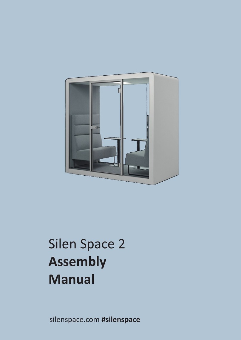
silen
silen Space 2 Assembly manual
Middle Atlantic Products
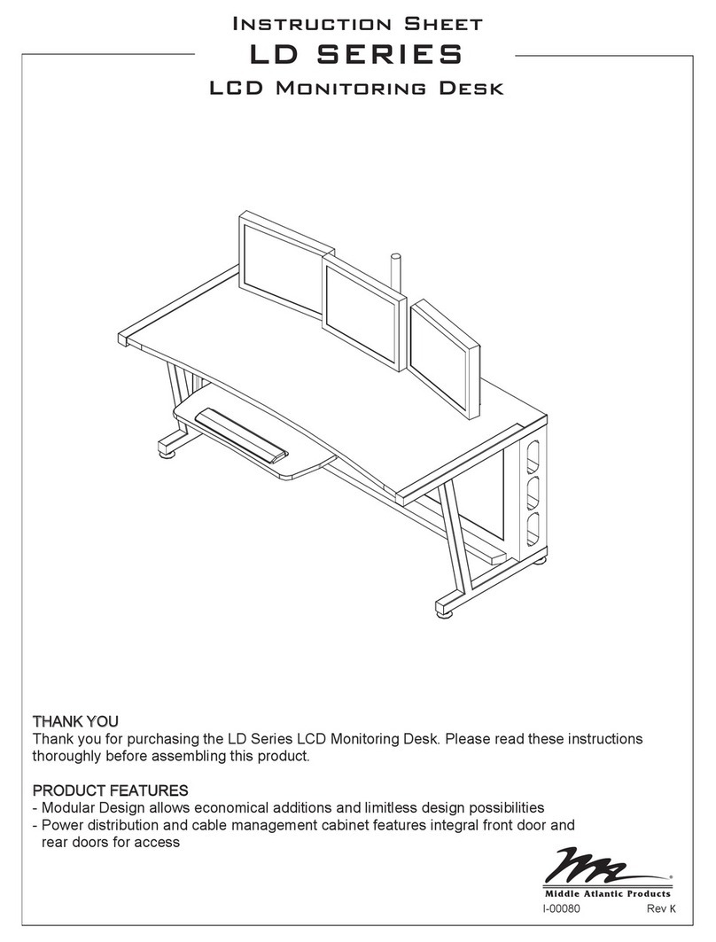
Middle Atlantic Products LD Series instruction sheet

SHFL
SHFL DECK MATE BLACKJACK Service manual

VITRA
VITRA Stefan Hürlemann Dancing Wall Assembly instructions
BISLEY
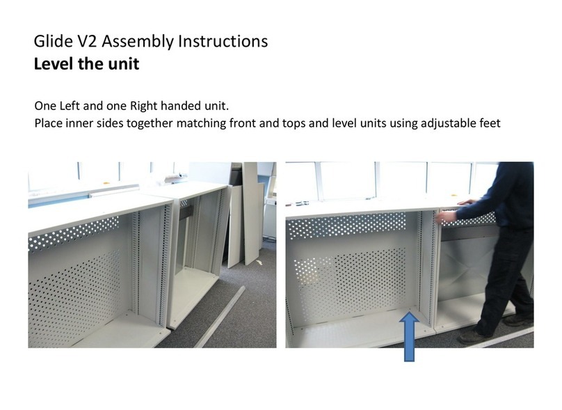
BISLEY Glide V2 Assembly instructions

