Allsteel Stride User manual

Allsteel Inc.
Muscatine, Iowa 52761-0071
www.allsteeloffice.com
ZAPE-E
343-2152G
(8/12)
Stride Installation Packet
Index
System Guidelines .........................................Pages 1 thru 3
Panel Frame Connections...................................Pages 4 thru 11
Base Raceway Cover Removal ....................................Page 12
Footed Panel Adjustment ......................................... Page 13
Low Profile Glass Installation ...............................Pages 14 thru 23
Panel Mounted Screen Installation ...........................Pages 24 thru 26
Glass Panel Mounted Screen Installation ......................Pages 27 thru 28
Trim Installation ..........................................Pages 29 thru 33
Panel Tile Installation .....................................Pages 34 thru 45
Non-Rail Based Off-Modular Installation.......................Pages 46 thru 55
Worksurfaces......................................Pages 46 thru 47
Panel ............................................Pages 48 thru 52
Storage ..........................................Pages 53 thru 55
Rail Based Off-Modular Installation...........................Pages 56 thru 68
Panel ............................................Pages 59 thru 65
Storage ................................................. Page 66
Worksurfaces......................................Pages 67 thru 68
Door Panel Installation ....................................Pages 69 thru 70
Power Pole and Trim Installation.............................Pages 71 thru 72
8-Wire Electrical Installation ................................Pages 73 thru 77
Data Terminal Installation ......................................... Page 78
Overhead Storage Installation...............................Pages 78 thru 85
Permanent Wall Hanger Installation ................................. Page 86
Worksurface Supports Installation............................Pages 87 thru 97
Countertop Installation ...................................Pages 98 thru 101
Spanning tile installation .................................Pages 102 thru 108
Pour des instructions en francais, appeler le 800-822-7653
Para instrucciones en espanol, llame al 800-822-7653
Stride
Installation Instructions
3430215200 J
Contents
System Guidelines. . . . . . . . . . . . . . . . . . . . . 1
Panel Frame Connections...............4
Base Raceway Cover Removal..........12
Footed Panel Adjustment ..............13
Low Prole Glass Installation ...........14
Glass Panel Mounted Screen Installation ..24
Trim Installation ......................25
Panel Tile Installation. . . . . . . . . . . . . . . . . . 33
Non-Rail Based Off Modular Installation ...43
Door Panel Installation ................52
Power Pole and Trim Installation.........53
8-Wire Electrical Installation ............55
Data Terminal Installation ..............60
Overhead Storage Installation...........60
Permanent Wall Hanger Installation ......68
Worksurface Supports Installation........69
Countertop Installation. . . . . . . . . . . . . . . . . 80
Spanning Tile Installation. . . . . . . . . . . . . . . 84
Allsteel Inc.
Muscatine, Iowa 52761-0071
www.allsteeloffice.com
ZAPE-E
343-2152G
(8/12)
Stride Installation Packet
Index
System Guidelines .........................................Pages 1 thru 3
Panel Frame Connections...................................Pages 4 thru 11
Base Raceway Cover Removal ....................................Page 12
Footed Panel Adjustment ......................................... Page 13
Low Profile Glass Installation ...............................Pages 14 thru 23
Panel Mounted Screen Installation ...........................Pages 24 thru 26
Glass Panel Mounted Screen Installation ......................Pages 27 thru 28
Trim Installation ..........................................Pages 29 thru 33
Panel Tile Installation .....................................Pages 34 thru 45
Non-Rail Based Off-Modular Installation.......................Pages 46 thru 55
Worksurfaces......................................Pages 46 thru 47
Panel ............................................Pages 48 thru 52
Storage ..........................................Pages 53 thru 55
Rail Based Off-Modular Installation...........................Pages 56 thru 68
Panel ............................................Pages 59 thru 65
Storage ................................................. Page 66
Worksurfaces......................................Pages 67 thru 68
Door Panel Installation ....................................Pages 69 thru 70
Power Pole and Trim Installation.............................Pages 71 thru 72
8-Wire Electrical Installation ................................Pages 73 thru 77
Data Terminal Installation ......................................... Page 78
Overhead Storage Installation...............................Pages 78 thru 85
Permanent Wall Hanger Installation ................................. Page 86
Worksurface Supports Installation............................Pages 87 thru 97
Countertop Installation ...................................Pages 98 thru 101
Spanning tile installation .................................Pages 102 thru 108
Pour des instructions en francais, appeler le 800-822-7653
Para instrucciones en espanol, llame al 800-822-7653
Allsteel Inc.
Muscatine, Iowa 52761-0071
www.allsteelofce.com
343-2152G
PAGE 1 OF 108 (8/12)
Stride Installation Packet
Stride Installation Packet
Illustration 1
Illustration 2
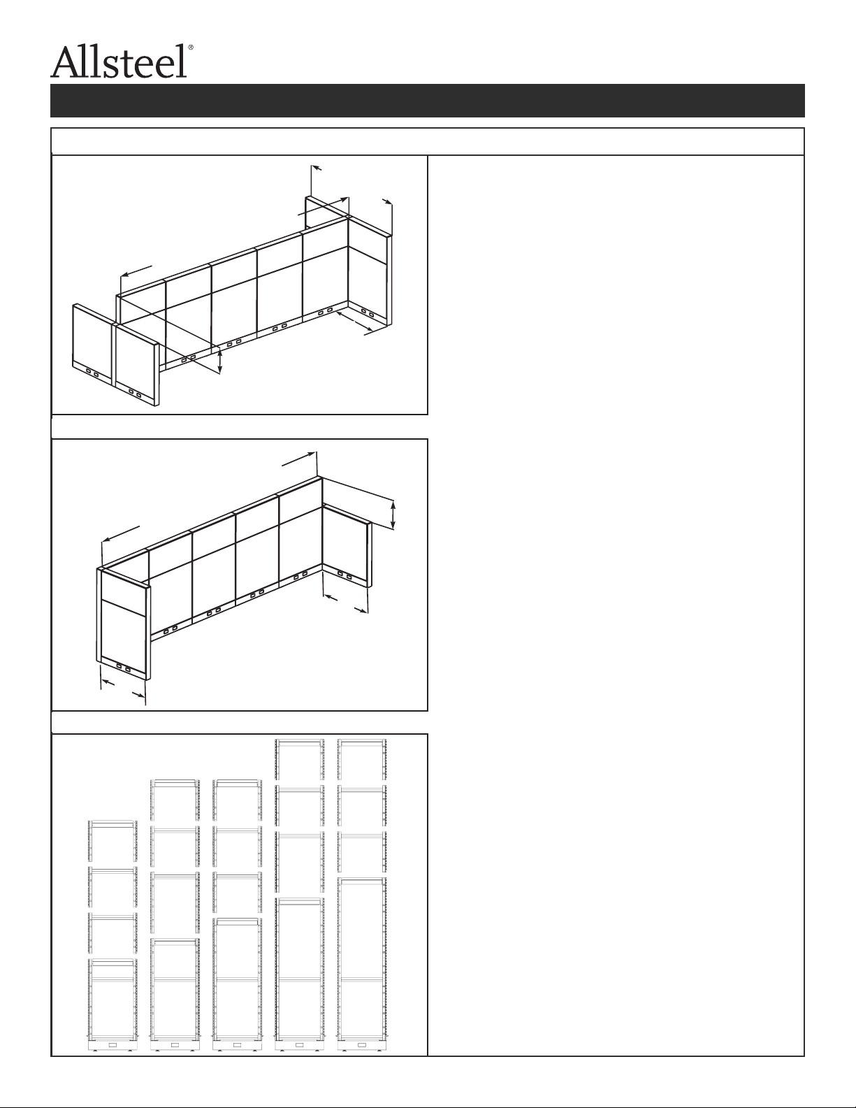
STRAIGHT PANEL GUIDELINES:
Definitions:
Parent Panel Run - Panels (or a single panel)
configured in a straight line intended to divide space.
It is usually longer than the panels used to stabilize it.
Return Panels - Panels attached to a parent run for
the purpose of stabilizing it.Return panels may also
have the effect of dividing space.
FOR ADEQUATE STABILITY of the Allsteel Stride
freestanding wall partitions, one of two methods of
stabilization must be used:
Method 1. - Refer to Illustration 1.A parent panel run
must have a minimum of two return panels extended
in opposing directions on each side of the parent run.
Notes: A single return panel (48" minimum length)
may be used with a Non-Rail Based Off-
Modular connector.The panel must extend at
least 22" from one side of the parent run.
Return panels must be no more than 30"
lower than the maximum height of the parent
panel run.
Method 2. - Refer to Illustration 2.A parent panel run
must be a minimum of 48" and a maximum of 12 feet,
and must have at least two return panels totaling at
least 58% of the length of the parent run extended in
one direction.The minimum length of a return
panel(s) should total 60".
Note: Return panels must be no more than 30"
lower than the maximum height of the parent
panel run.
X plus Y must total the greater of:
(A) 58% of the parent run length, or
(B) 60"
Z must be no greater than 30"
Y
Z
48" minimum
30" maximum
22" minimum
Illustration 3
• Stack-on frames can be installed on top of any
structural panel frames.
• A maximum of three stack-on frames, totaling no
more than 52.5", can be added to a base panel
frame to a maximum height of 110".
• 15" and 30" stack-on frames should be added to
35", 50", and 65" base frames to maintain hang
slot modularity.
• 22.5" stack-on frames should be added to 42.5"
and 57.5" base frames to maintain hang slot
modularity.
• A 15" stack-on frame can be used on top of a
22.5" stack-on frame with no loss of modularity
of hang slots.
PANEL HEIGHT LIMITATIONS (refer to Illustration 3):
35
15
15
15
42.5
22.5
15
15
50
15
15
15
57.5
22.5
15
15
65
15
15
15
X
12' maximum
48" minimum
12' maximum
48" minimum
15”
381 mm
15”
381 mm
15”
381 mm
15”
381 mm
15”
381 mm
22.5”
571.5 mm
22.5”
571.5 mm
65”
1651 mm
57.5”
1460.5 mm
50”
1270 mm
42.5”
1079.5 mm
35”
889 mm
343-2152G
PAGE 1 OF 108 (8/12)
Stride Installation Packet
Stride Installation Packet
Illustration 1
Illustration 2
STRAIGHT PANEL GUIDELINES:
Definitions:
Parent Panel Run - Panels (or a single panel)
configured in a straight line intended to divide space.
It is usually longer than the panels used to stabilize it.
Return Panels - Panels attached to a parent run for
the purpose of stabilizing it.Return panels may also
have the effect of dividing space.
FOR ADEQUATE STABILITY of the Allsteel Stride
freestanding wall partitions, one of two methods of
stabilization must be used:
Method 1. - Refer to Illustration 1.A parent panel run
must have a minimum of two return panels extended
in opposing directions on each side of the parent run.
Notes: A single return panel (48" minimum length)
may be used with a Non-Rail Based Off-
Modular connector.The panel must extend at
least 22" from one side of the parent run.
Return panels must be no more than 30"
lower than the maximum height of the parent
panel run.
Method 2. - Refer to Illustration 2.A parent panel run
must be a minimum of 48" and a maximum of 12 feet,
and must have at least two return panels totaling at
least 58% of the length of the parent run extended in
one direction.The minimum length of a return
panel(s) should total 60".
Note: Return panels must be no more than 30"
lower than the maximum height of the parent
panel run.
X plus Y must total the greater of:
(A) 58% of the parent run length, or
(B) 60"
Z must be no greater than 30"
Y
Z
48" minimum
30" maximum
22" minimum
Illustration 3
• Stack-on frames can be installed on top of any
structural panel frames.
• A maximum of three stack-on frames, totaling no
more than 52.5", can be added to a base panel
frame to a maximum height of 110".
• 15" and 30" stack-on frames should be added to
35", 50", and 65" base frames to maintain hang
slot modularity.
• 22.5" stack-on frames should be added to 42.5"
and 57.5" base frames to maintain hang slot
modularity.
• A 15" stack-on frame can be used on top of a
22.5" stack-on frame with no loss of modularity
of hang slots.
PANEL HEIGHT LIMITATIONS (refer to Illustration 3):
35
15
15
15
42.5
22.5
15
15
50
15
15
15
57.5
22.5
15
15
65
15
15
15
X
12' maximum
48" minimum
12' maximum
48" minimum
Straight Panel Guidelines:
Denitions:
Parent Panel Run - Panels (or a single panel) congured in
a straight line intended to divide space. It is usually longer
than the panels used to stabilize it.
Return Panels - Panels attached to a parent run for the
purpose of stabilizing it. Return panels may also have the
effect of dividing space.
FOR ADEQUATE STABILITY of the Allsteel Stride
freestanding wall partitions, one of two methods of
stabilization must be used:
Method 1. - Refer to Illustration 1. A parent panel run must
be a minimum of 48” (1219.2 mm) , a maximum of 12 feet,
(3.657 meters) and must have a minimum of two return
panels (totaling 20% of the length of the parent run) extended
in opposing directions on each side of the parent run.
Note - A single return panel (48” (1219.2 mm) minimum
length) may be used with Non-Rail Based Off-Modular
connector. The panel must extend at least 22” (558.8
mm) from one side of the parent run.
Return panels must be no more than 30” (762 mm)
lower than the maximum height of the parent panel
run.
Method 2. - Refer to Illustration 2. A parent panel run must
be a minimum of 48” (1219.2 mm), a maximum of 12 feet,
(3.657 meters) and must have at least two return panels
totaling at least 58% of the length of the parent run extended
in one direction. The minimum length of a return panel(s)
should total 60” (1524 mm).
Note - Return panels must be no more than 30” (762 mm)
lower than the maximum height of the parent panel
run.
Panel height limitations (refer to Illustration 3):
Stack-on frames can be installed on top of any
structural panel frames.
A maximum of three stack-on frames, totaling no
more than 52.5” (1333.5 mm), can be added to a base panel
frame to a maximum height of 110” (2794 mm).
15” (381 mm) and 30” (762 mm) stack-on frames should be
added to 35” (889 mm), 50”(1270 mm), and 65” (1651 mm)
base frames to maintain hang slot modularity
22.5” (571.5 mm) stack-on frames should be added to 42.5”
(1079.5 mm) and 57.5” (1460.5 mm) base frames to
maintain hang slot modularity
A 15” (381 mm) stack-on frame can be used on top of a
22.5” (571.5 mm) stack-on frame with no loss of modularity
of hang slots
Illustration 1.
Illustration 2.
Illustration 3.
30” (762 mm)
Maximum
48” (1219.2 mm)
Minumum
144” (3657.6 mm) Maximum
48” (1219.2 mm) Minimum
144” (3657.6 mm) Maximum
48” (1219.2 mm) Minimum
X plus Y must total the greater of:
(A) 58% of the parent run length or
(B) 60” (1524 mm)
(Z) must be no greater than 30” (762 mm)
15”
381 mm
15”
381 mm
15”
381 mm
15”
381 mm
15”
381 mm
15”
381 mm
15”
381 mm
15”
381 mm
24” (609.6mm)
Minimum
Stride Installation Packet
Page 1 of 903430215200 J
(09/19)

343-2152G
PAGE 2 OF 108 (8/12)
Stride Installation Packet
Stride Installation Packet
Illustration 4
Illustration 5
STACKING TO DOOR HEIGHT
Refer to Illustration 5.To stack to the 87.5"
door height, some loss of hang slot
modularity will occur.
STACKING LIMITATIONS
Stack-on frames do not have a hang slot
at the bottom of the vertical tube.
Due to this absence, hanging
components that utilize multiple,
consecutive hang slots cannot span the
joint of a base frame and a stack-on
frame or the joint of two stack-on
frames.
If a 22.5" stack-on frame is used on top
of a 35", 50", or 65" base frame, or on
top of a 15" or 30" stack-on frame, a
shift will occur in the overall height of the
hang slots.This will result in a height
variation of adjacent hanging
components.
No hanging components can span the
joint of a base frame and a stack-on
frame or the joint of two stack-on frames
if a 22.5" stack-on frame is used on top
of a 35", 50", or 65" base frame or a 15"
or 30" stack-on frame.
15
35
22.5
35
22.5
65
22.5
15
50
22.5”
571.5 mm
65”
1651 mm 50”
1270 mm
35”
889 mm
35”
889 mm
22.5”
571.5 mm
22.5”
571.5 mm
STACKING LIMITATIONS:
Stack-on frames do not have a hang slot at
the bottom of the vertical tube.
Due to this absence, hanging components
that utilize multiple, consecutive hang
slots cannot span the joint of a base
frame and a stack-on frame or the joint of
two stack-on frames.
If a 22 5” (571.5 mm) stack-on frame is
used on top of a 35” (889 mm), 50”(1270
mm), or 65” (1651 mm) base frame, or
on top of a 15” (381 mm) or 30” (762 mm)
stack-on frame, a shift will occur in the
overall height of the hang slots. This will
result in a height variation of adjacent
hanging components.
No hanging components can span the
joint of a base frame and a stack-on
frame or the joint of two stack-on frames
if a 22 5” (571.5 mm) stack-on frame is
used on top of a 35” (889 mm), 50”(1270
mm), or 65” (1651 mm) base frame or a 15”
(381 mm) or 30” (762 mm) stack-on frame.
STACKING TO DOOR HEIGHT:
Refer to Illustration 5 to stack to the 87.5”
(2222.5 mm) door height, some loss of hang
slot modularity will occur
Illustration 4.
Illustration 5.
15”
381 mm
15”
381 mm
Stride Installation Packet
Page 2 of 90
3430215200 J
(09/19)

PAGE 3 OF 108 (8/12)
Stride Installation PacketStride Installation Packet
Illustration 7
Return panels
Overhead
storage unit
Illustration 6
Return panels
Overhead
storage unit
Refer to Illustration 7.When a parent run is
supported with return panels on each side of
overhead storage units, a maximum of 5 units
can be suspended from each side of the parent
panel.
Refer to Illustration 6.In a panel run, only two
overhead storage cabinets or open storage
shelves are recommended per side, per panel.If
using a non-rail based off-modular panel
connector kit at one or both ends, do not
suspend more than one overhead storage unit
per side, per panel of the parent panel run.
When overhead storage units are suspended from
stack-on frames, the following guidelines must be
followed:
• Whenastorageunitissuspendedfroma
stack-on frame, all parent run panels and at least
the first panel of each return panel run must be
the same height as the supporting stack-on
panel, using base frames or a combination of
base frames and stack-on frames.
• Amaximumoftwooverheadstorageunits
should be suspended from each side of stack-on
frames on any given panel.
OVERHEAD STORAGE GUIDELINES:
Page 3 of 903430215200 J
(09/19)

PAGE 4 OF 108 (8/12)
Stride Installation Packet
Stride Installation Packet
WARNING
Illustration 8. Frame-To-Frame Connection (attachment screws provided with panel frames)
Detail 8A. Top View
Step 1 - Place frames so that leveling blocks nest together.
To insure that the two panels line up, adjust the
leveling glides on the bottom of the panels.
Note: Refer to Detail 8A.Top View for alignment of
leveling blocks.
Step 2 - Install attachment screws through larger hole in one frame and into the smaller
mating hole of adjacent frame.Fully tighten screws.Start by installing attachment
screw through the top location in the frame and work down alternating left to right.
Total Number of Screws
Required for Panel Frames
Panel Height
35"
42.5"
50"
57.5"
2
3
3
4
Screws
65" 4
IMPORTANT - For proper fit all
panels must be
level.
Failure to install product as instructed,
use of hardware other than that which
is provided with product, or failure to
comply with instructions can result in
product failure, personal injury, or
property damage.
NOTE: Start with the lower
hole at the top position,
and alternate left and
right from there down.
Refer to Pages 1-3 for
Installation Guidelines
Right
Right
Left
Left
Total Number of Screws
Required for Panel Frames
Panel Height Screws
35” (889 mm)
42.5” (1079.5 mm)
50” (1270 mm)
57.5” (1460.5 mm)
65” (1651 mm)
2
3
3
4
4
Page 4 of 90
3430215200 J
(09/19)

PAGE 5 OF 108 (8/12)
Stride Installation Packet
Stride Installation Packet
Illustration 9. Stack-On Frame Installation
IMPORTANT: Tiles must be removed from stack-on
frame and base panel frame prior to
stack-on frame installation.
Step 3 - Install screws through base panel
and into attachment bracket (two
.75" screws if end of run condition,
one .75" and one 2.5" if inline
condition).
Step 4 - Position stack-on frame onto
attachment brackets.
Step 2 - Insert attachment brackets into base
panel (each side).Note bracket
orientation.
Step 1 - Remove top cap, top cap retainers, and
center clip block from base panel frame
and install on stack-on frame.Refer to
Illustration 34 for top cap retainer
removal.
IMPORTANT: .75" screws in Steps 3 and 5 must be
replaced by 2.5" screws for panel
connections if frames attached in an inline
condition (see Illustration 8 for guidelines).
Attachment
Bracket
Base Panel Frame
Stack-On Frame
Step 5 - Install screws through stack-on frame and
into attachment bracket (two .75" screws if
end of run condition, one .75" and one 2.5" if
inline condition).
Page 5 of 903430215200 J
(09/19)

PAGE 6 OF 108 (8/12)
Stride Installation Packet
Stride Installation Packet
Illustration 10. Frame-To-Frame Connection at 90°, “T”, “X” and
Extended Straight Panel Junctures (common height)
Step 1 - Determine the configuration of the panels at the connector juncture and ensure that the connector block for
that juncture has the correct number of spacers.The side that has the outdent will always mate to a frame.
Any additional frames mating to the connector will need a spacer added to the connector block.
90° Connector “S” Connector
(Extended Straight)
“T” Connector “X” Connector
Outdent
SpacerSpacer
Spacers attached
only on sides that
mate to frames
This side always mates to a frame.
No spacer necessary.
Page 6 of 90
3430215200 J
(09/19)

PAGE 7 OF 108 (8/12)
Stride Installation PacketStride Installation Packet
Illustration 10a. Frame-To-Frame Connection at 90°, “T”, “X” and Extended
Straight Panel Junctures (common height)
Total Number of Connector
Blocks Required for Panel Frames
Panel Height
35"
42.5"
50"
57.5"
65"
2
3
3
3
4
Blocks
Step 2 - Attach the connector blocks to panel frames with one screw per block, per panel.Start on the left hole
of the lowest position on the panel frame.Refer to the table below for the correct number of connector
blocks per connector juncture.Evenly space the remaining connector blocks along the frame making
sure to place one at the highest position on the panel.Determine whether the left or right hole should
be used at each connector block position with the following rules:
- Where full data space is needed near a connector block, use the left hole at that connector position.
- 2 blocks: Use the left hole for both blocks
- 3 blocks: Use the left hole for two blocks and the right hole for one.
- 4 blocks: Use the left hole for two blocks and the right hole for two blocks.
Full Data
Opening
Right
Right
Left
Left
Partial Data
Opening
Section view of 65"H
panel frame with four
connector blocks.
Total Number of Connector Blocks
Required for Panel Frames
Panel Height Screws
35” (889 mm)
42.5” (1079.5 mm)
50” (1270 mm)
57.5” (1460.5 mm)
65” (1651 mm)
2
3
3
3
4
Section view of 65”
(1651 mm) panel
frame with four
connector blocks
Page 7 of 903430215200 J
(09/19)

3430215200 J
PAGE 8 OF 108 (8/12)
Stride Installation PacketStride Installation Packet
Illustration 11. Installing Connector Blocks with Stack-On Frames
Step 1 - Refer to Illustration 10 for the correct connector block configuration and orientation
Step 2 - Ensure that there is one connector block at the top and bottom of each stack-on frame, and at the
top of each base frame.
Step 3 - Refer to Step 2 of Illustration 10a to ensure that all required connector blocks have been installed.
Connector
Block for
bottom of 15"
Stack-On
Frame
50" Base Frame
15" Stack-On
Frame
Connector Block
for top of both
Stack-On Frames
30" Stack-On
Frame
Connector Block
for bottom of 30"
Stack-On Frame
Connector Block
for top of 65"
Base Frame
65" Base Frame
30” (762 mm)
Stack-On Frame
15” (381 mm)
Stack-On Frame
Connector Block
for bottom of
15” (381 mm)
Stack-On Frame
Connector Block for
top of 65” (1651 mm)
Base Frame
Connector Block
for bottom of
30” (762 mm)
Stack-OnFrame
50” (1270 mm) Base Frame 65” (1651 mm) Base Frame
Page 8 of 90
(09/19)

343-2152G
PAGE 9 OF 108 (8/12)
Stride Installation Packet
Stride Installation Packet
Illustration 12. Light Block Installation
Step 1 - If light block is being used in a variable
height application, cut the light block to
the same height as the shortest panel it
will be adjacent to.
“L” Light Block
Step 2 - Once the connector blocks are secured to
the frames, press the light block into the
connector block.The top of the light
block should be flush with the top of the
panel frame vertical.
“X” Light Block
“T” Light Block
Illustration 12. Light Block Installation
Stride Installation Packet
Page 9 of 903430215200 J
(09/19)

343-2152G
PAGE 10 OF 108 (8/12)
Stride Installation Packet
Stride Installation Packet
Illustration 13. Frame-To-Frame Variable Height Connection
Step 1 - In variable height applications, place connector blocks on shortest base panel, according to the table in Illustration
10a.
Step 2 - Place 1 connector block for each 7.5" level change and 2 connector blocks for each 15" or greater level change
above top of the shortest base panel.A level change is defined as any change in height from the top of one
frame, base frame or stack-on frame, to the top of the next highest frame, until there are less than 2 frames
higher than the last level.
Step 3 - Snap variable height trim onto connector blocks and frames as shown in illustration 32.
57.5" high panel
57.4" high light block
7
.5" high 90°
filler trim
50" high panel
7.5" high end trim
90° top cap transition
piece
65" high panel
35" high panel
End Trim
Transition Piece
15" high flat filler trim
50" high
light block
35" high light block
“X”, “T”, and 90°
configured connector
blocks
Step 1 - In variable height applications, place connector blocks on shortest base panel, according to the table in
Illustration 10a.
Step 2 - Place 1 connector block for each 7.5” (190.5 mm) level change and 2 connector blocks for each 15” (381 mm)
or greater level change above top of the shortest base panel A level change is dened as any change in height
from the top of one frame, base frame or stack-on frame, to the top of the next highest frame, until there are
less than 2 frames higher than the last level.
Step 3 - Snap variable height trim onto connector blocks and frames as shown in illustration 30.
Illustration 13. Frame-to-Frame Variable Height Connection
57.5” (1460.5 mm)
high panel
57.4” (1467.9 mm)
light block
65” (1651 mm)
high panel
7.5” (190.5 mm)
high 90° ller trim
7.5” (190.5 mm)
high end trim
15” (381 mm)
high at ller trim
35” (889 mm)
high panel
35” (889 mm) high
light block
50” (1270 mm)
high light block
50” (1270 mm)
high panel
Stride Installation Packet
Page 10 of 90
3430215200 J
(09/19)

PAGE 11 OF 108 (8/12)
Stride Installation PacketStride Installation Packet
Illustration 14. Permanent Wall Mount Connection
Step 1 - Remove screw to take leveling block off of the side of panel that will be
affixed to the wall mount.
Step 2 - Ensure that the wall mount is vertically plumb.
Step 3 - With top caps off, align top of wall mount to top of panel frame vertical.
Step 4 - Attach wall mount to wall using appropriate attachment hardware (wood
screws 2-1/2" minimum length) into studs, or Molly-type fastener (not
provided) into drywall, through the large diameter holes.
Step 5 - Connect panel frame to wall mount using the attachment screws included
with the panel (refer to Illustration 8 and copy the panel-to-panel
attachment method).
Wall Mount Top Cap
Trim Connector
Panel Top Cap
Panel Frame
Attachment Screw
Wall Mount
Notch identifies
top of wall mount.
Larger diameter holes
are used for fastening
wall mount to the wall.
Smaller diameter holes
are used for fastening
wall mount to the panel.
Leveling
block
Page 11 of 903430215200 J
(09/19)

3430215200 J
PAGE 12 OF 108 (8/12)
Stride Installation Packet
Stride Installation Packet
Illustration 15. Baserail Cover Removal
Step 1 - Insert flat blade screwdriver between Baserail cover
and bottom frame horizontal.Pivot screwdriver
upward to free Baserail cover from glide towers.
Step 2 - Repeat Step 1 on opposite end of panel frame.
Step 3 - Lift Baserail cover free of panel frame.
Page 12 of 90
(09/19)
343-2152G
PAGE 13 OF 108 (8/12)
Stride Installation PacketStride Installation Packet
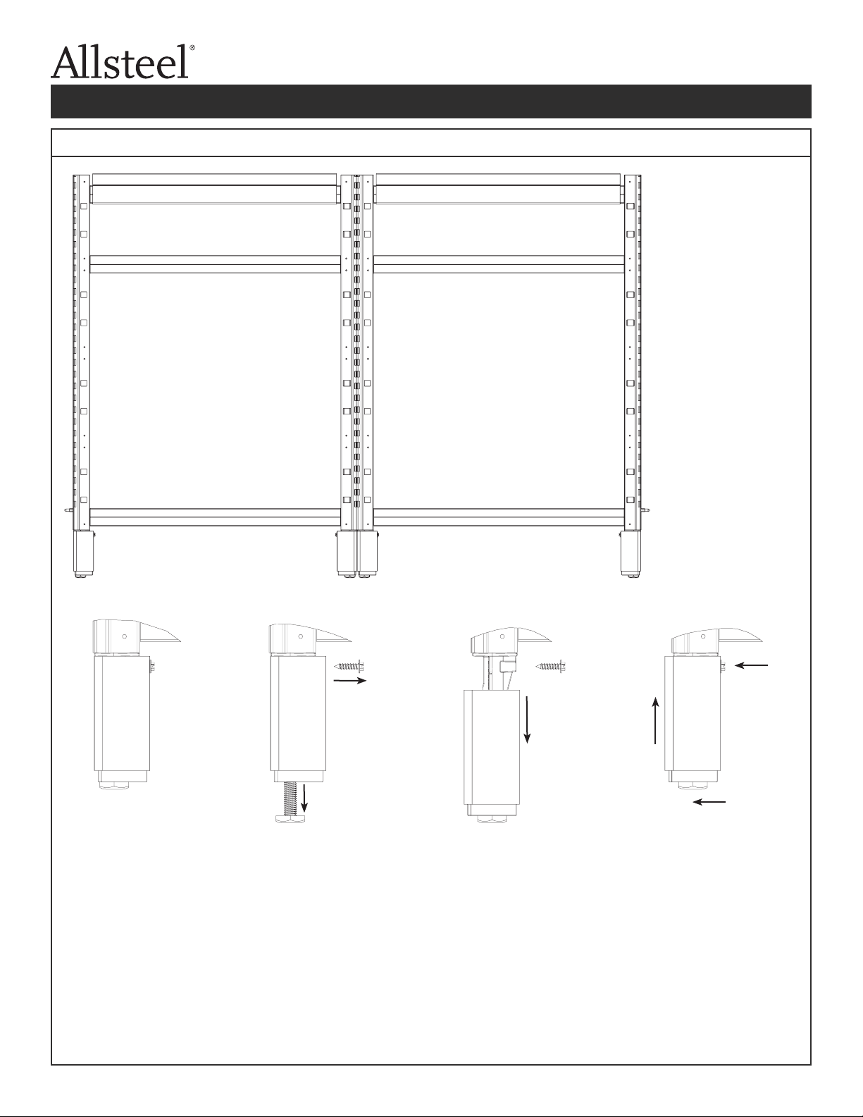
Illustration 16. Footed Panel Adjustment
To adjust panel
foot for end of
run application:
Step 1 -
Extend leveler about
1" and remove
attachment screw.
A 2x4 should be
placed under the
bottom horizontal
member of the panel
frame if using a pry
bar to raise the
panel frame.Do not
pry up on the panel
foot.
Step 2 -
Lower panel foot
sleeve and cover.
Step 3 -
Shift cover and sleeve
over 1/4", and raise
back up, reattach with
screw, and retract
leveler.
NOTE: Footed
panels are shipped
ready to be installed
in an in-line
application.
3rd
1st
2nd
Step 1 - Extend leveler about
1” (25.4 mm) and
remove attachment
screw
A 2x4 should be
placed under the
bottom horizontal
member of the panel
frame if using a pry
bar to raise the panel
frame do not pry up
on the panel foot.
To adjust panel
foot for end of
run application:
Step 2 -Lower panel foot
sleeve and cover.
Step 3 - Shift cover and sleeve
over 1/4” (6.35 mm),
and raise back up,
reattach with screw,
and retract leveler
Illustration 16. Footed Panel Adjustments
Stride Installation Packet
Page 13 of 903430215200 J
(09/19)

343-2152G
PAGE 14 OF 108 (8/12)
Stride Installation PacketStride Installation Packet
Illustration 17. Low Profile Glass - Support Brackets
IMPORTANT - When spanning multiple frames, mount
support brackets to all base panels.Ensure
panels are level.
Step 1 - Remove top cap and set aside.
Top Cap
Illustration 17. Low Prole Glass - Support Brackets
Stride Installation Packet
Page 14 of 90
3430215200 J
(09/19)

343-2152G
PAGE 15 OF 108 (8/12)
Stride Installation PacketStride Installation Packet
Illustration 18. Low Profile Glass (LPG) Installation
IMPORTANT:
•Review Illustrations 19-27 to determine proper assembly based on end connection.
•Top tile on each side of base panel must be removed prior to LPG installation.
Step 1 - Remove outer vertical rib
(painted black) as
required depending on
end connection (see
Illustration 19-27 for end
conditions).
Step 4 -
Insert screw
through panel frame
into stacking bracket
in upper left location
first on both ends
(3/4" screw).
Step 2 - Remove upper panel connector screws (skip
this step at end of panel run).
Step 3 -
Insert stacking
bracket into base
panel verticals and
lower glass assembly
into place.
Step 5 - Replace panel connector screw from Step 2
into lower right hole.If no panel connector
screw is used, use the 3/4" screw from Step 4.
Outer vertical rib
Illustration 18. Low Prole Glass (LPG) Installation
Stride Installation Packet
Page 15 of 903430215200 J
(09/19)

343-2152G
PAGE 16 OF 108 (8/12)
Stride Installation PacketStride Installation Packet
Illustration 19. Low Profile Glass - In-Line Connection - LPG to Panel
Step 1 - Install LPG (see Illustration 18).
Step 2 -
Secure LPG to adjacent base panel using 2.5" frame
connector screw in an alternating pattern.Refer to
Illustration 20.
Screw locations for panel attachment - only
the locations shown can be used.
Always use upper
right location
Always use lower
left location
May use these
locations
Illustration 20. LPG Screw Hole Location Options
343-2152G
PAGE 16 OF 108 (8/12)
Stride Installation PacketStride Installation Packet
Illustration 19. Low Profile Glass - In-Line Connection - LPG to Panel
Step 1 - Install LPG (see Illustration 18).
Step 2 - Secure LPG to adjacent base panel using 2.5" frame
connector screw in an alternating pattern.Refer to
Illustration 20.
Screw locations for panel attachment - only
the locations shown can be used.
Always use upper
right location
Always use lower
left location
May use these
locations
Illustration 20. LPG Screw Hole Location Options
Step 1 - Install LPG (see Illustration 18)
Step 2 - Secure LPG to adjacent base panel using
2.5” (6.35 mm) frame connector screw in an
alternating pattern. Refer to Illustration 20.
Illustration 19. Low Prole Glass - In-Line Connection - LPG to Panel
Illustration 20. LPG Screw Hole Location Options
Stride Installation Packet
Page 16 of 90
3430215200 J
(09/19)

PAGE 17 OF 108 (8/12)
Stride Installation PacketStride Installation Packet
Illustration 21. Low Profile Glass - In-Line Connection - LPG to LPG
Step 1 - Install first LPG (see Illustration 18).
Step 2 - Remove vertical rib from each LPG.
Step 3 - Reattach both vertical ribs to the first LPG using 1.5" screw provided as shown.
Fasten screws through same holes where vertical ribs were initially attached.
Step 4 - Install second LPG, securing the stacking bracket furthest from the first LPG first.
Note: Tie bracket is required for this configuration.See Illustration 28.
Step 3
Secure the bracket opposite
the first LPG first.
Page 17 of 903430215200 J
(09/19)

3430215200 J
PAGE 18 OF 108 (8/12)
Stride Installation Packet
Stride Installation Packet
Illustration 22. Low Profile Glass - Connector Block Pre-Assembly
When LPG is used at a connector block connection, it is necessary to
pre-assemble 1 or 2 LPG vertical rib components to the connector
blocks prior to LPG installation.
IMPORTANT - See Illustrations 24-27 for number of vertical rib
components to pre-assemble.Do not install more than
two vertical ribs to the subassembly.
Step 1 - Attach required number of connector blocks to
1 vertical rib using 1.5" screws provided (same as
above).
Step 2 - Attach a second vertical rib, creating an “L”
configuration (only if second vertical rib is required).
Illustration 23. Low Profile Glass - Vertical Rib Installation
IMPORTANT - When reinstalling vertical rib, tabs should insert into groove in LPG verticals as shown
Vertical Rib
Connector
Block
Page 18 of 90
(09/19)

PAGE 19 OF 108 (8/12)
Stride Installation PacketStride Installation Packet
Illustration 24. Low Profile Glass - 1 LPG at Connector Block Connection
These instructions cover configurations with 1 LPG and 1 to 3 base panels at a connector block connection.
NOTE: If multiple base panels are already installed with connector blocks, connector blocks for LPG must be removed
prior to Step 1.
Step 1 - Remove vertical rib from one end and attach
connector blocks (see Illustration 22.)
Step 2 - Attach vertical rib subassembly to LPG reusing
screws from Step 1.
Step 4 - Secure other base
panels to connector
blocks.
Step 3 - Install LPG (see
Illustration 19).
NOTE: Tie bracket not required for
this configuration.
Page 19 of 903430215200 J
(09/19)
Table of contents
Other Allsteel Office Equipment manuals

Popular Office Equipment manuals by other brands

hushoffice
hushoffice hushtwin HUS-BX-019 Maintenance and safety manual

silen
silen Space 2 Assembly manual

Middle Atlantic Products
Middle Atlantic Products LD Series instruction sheet

SHFL
SHFL DECK MATE BLACKJACK Service manual

VITRA
VITRA Stefan Hürlemann Dancing Wall Assembly instructions

BISLEY
BISLEY Glide V2 Assembly instructions


