Alltion AM-2000 User manual

AM-2000 Surgical Microscope
User's Manual
(Please read the instruction carefully before using it)
PA1805-UM01-EN
Version:A4
2019-12-25
Alltion (Guangxi) Instrument Co., Ltd.

Alltion (Guangxi) Instrument Co., Ltd.
Product Information:
Name: Surgical Microscope
Model:AM-2000
Production Date: See the instrument label for details
Manufacturer:
Alltion (Guangxi) Instrument Co., Ltd.
Address: No. 10, 3rd Road , Wuzhou Industrial Park, Wuzhou, Guangxi, China
E-mail: sales@alltion.com or sales@alltion-microscope.com
Tel: + 86-774-2836101
Fax: + 86-774-2836192
Postal Code: 543100
Website: http://www.alltion.com
After-Sale Service Provider:
Alltion (Guangxi) Instrument Co., Ltd.
Address: No. 10, 3rd Road , Wuzhou Industrial Park, Wuzhou, Guangxi, China
E-mail: sales@alltion.com or sales@alltion-microscope.com
Tel: + 86-774-2836101
Fax: + 86-774-2836192
Postal Code: 543100
Website: http://www.alltion.com

Alltion (Guangxi) Instrument Co., Ltd.
Contents
Safety Caution...............................................................................................................................................................1
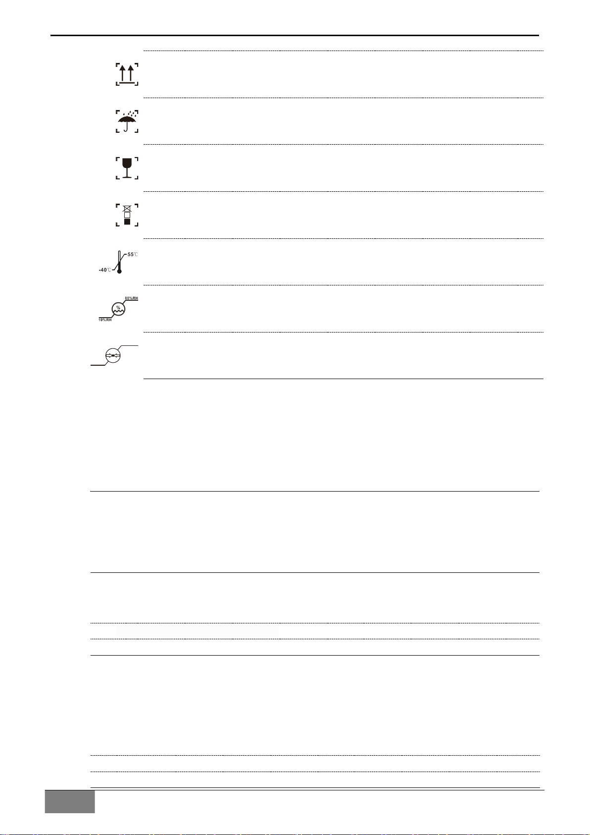
Prompt Symbols..................................................................................................................................................... 1
Information Symbols.............................................................................................................................................. 1
The meaning of other figures, symbols and contractions............................................................................... 1
Structure and Composition................................................................................................................................... 2
Range of Application..............................................................................................................................................2
Contraindication......................................................................................................................................................2
Service Life..............................................................................................................................................................2
Working Environment............................................................................................................................................ 2
Storage Environment............................................................................................................................................. 3
Safety Characteristics............................................................................................................................................3
Safety Requirements on Installation and Use................................................................................................... 3
Safety Requirements..................................................................................................................................... 3
Requirements on Installation........................................................................................................................3
Operating requirements................................................................................................................................ 4
Safety Signs on the Instrument............................................................................................................................4
Product Assembly........................................................................................................................................................6
Standard Configuration......................................................................................................................................... 6
Supporting Components....................................................................................................................................... 8
Inspection before Assembly................................................................................................................................11
Installation of Support System........................................................................................................................... 12
Installation of Mobile Floor Stand.............................................................................................................. 12
Installation of Fixed Floor Stand................................................................................................................ 13
Installation of Ceiling Mount....................................................................................................................... 14
Installation of Low-Position Wall Mount....................................................................................................15
High-Position Wall Mount............................................................................................................................16
Installation of Cross Arm System.......................................................................................................................17
Upright Installation of Cross Arm...............................................................................................................17
Suspending of Ceiling Mount..................................................................................................................... 18
Installation of Objective Lens............................................................................................................................. 19
Installation of Control handle..............................................................................................................................19
Installation of Binocular Head Barrel................................................................................................................ 20
Wiring..................................................................................................................................................................... 21
Installation Confirmation......................................................................................................................................22
Installation of Supporting Components............................................................................................................ 23
Installation of Straight Binocular Head and 45° Binocular Head......................................................... 23
Installation of Objective Lens..................................................................................................................... 23
Installation of Other Parts........................................................................................................................... 23
Product Functions..................................................................................................................................................... 24
Product Components........................................................................................................................................... 24
Main body lens of microscope............................................................................................................................25
180°binocular and eyepiece............................................................................................................................... 26
Objective lens........................................................................................................................................................27
120°Hanger bracket.............................................................................................................................................28
Cross arm and mobile floor stand\ fixed floor stand\ low-position wall mount stand................................29
Cross arm and ceiling mount system/high-position wall mount system..................................................... 31

Alltion (Guangxi) Instrument Co., Ltd.
Operation of the Microscope.................................................................................................................................. 33
Check before use................................................................................................................................................. 33
Optical adjustment of surgical microscope...................................................................................................... 34
Performance Parameters......................................................................................................................................... 35
Basic dimension....................................................................................................................................................35
Microscope Parameters...................................................................................................................................... 36
Optical parameters...............................................................................................................................................36
Electrical parameters........................................................................................................................................... 36
Electromagnetic Compatibility...............................................................................................................................37
Requirements on wire installation..................................................................................................................... 37
Key components for electromagnetic compatibility........................................................................................ 37
Guidance and manufacturers declaration–electromagnetic emission........................................................ 37
Guidance and manufacturer's declaration – electromagnetic immunity– for all EQUIPMENT and
SYSTEMS..............................................................................................................................................................38
Guidance and Statement from Manufacturer - Electromagnetic Immunity– for EQUIPMENT and
SYSTEM that are not LIFE-SUPPORTING..................................................................................................... 39
Recommended separation distances between portable and mobile RF communications equipment
and the AM-2000.................................................................................................................................................. 40
Cleaning and Maintenance of the Instrument....................................................................................................41
Preventive maintenance and inspection.......................................................................................................... 41
Clean the optical surface.................................................................................................................................... 41
Clean the mechanical surface............................................................................................................................41
Disposal of waste................................................................................................................................................. 41
Maintenance related information...........................................................................................................................42
Troubleshooting.................................................................................................................................................... 42

Alltion (Guangxi) Instrument Co., Ltd.
AM-2000 User’s Manual | Safety Caution
1
Safety Caution
When using the instrument, you must observe the safety instructions, and the meanings of these
symbols are as follows:
Prompt Symbols
The following safety information has been incorporated into the user manual. Please note this information
and be particularly careful in these cases, especially the contents with the following symbols.
Warning, indicating that there is potential hazard, failure to follow the instructions may
pose a risk of harming users or product failure!
Note, promoting the user of the instrument, or providing the useful information to the
user.
Information Symbols
The item symbols used in this User's Manual are defined as follows:
The content of the upper and lower items is equal, there is no sequence or
subordination relation.
The precondition of operation, the precondition that the product must meet before
performing a certain operation.
There is a sequential relationship between the upper and lower items, and the next
step can be carried out after the previous step is completed.
Results occurred after completion of related operations.
The meaning of other figures, symbols and contractions
Please refer to the User's Manual.
Manufacturer
PD
Date of manufacture
Authorized representative in the European Community
CE label
Power Switch
No pushing

Alltion (Guangxi) Instrument Co., Ltd.
2
Safety Caution |AM-2000 User’s Manual
Upward
Keep dry
Handle With Care
2
The number of stacked layers must not exceed 2 layers
Ambient temperature range: -40℃~55℃
Relative humidity range: 10%~80%
1060hPa
500hP a
Atmospheric pressure range: 500 hPa~1060 hPa
Structure and Composition
AM-2000 Surgical Microscope consists of support bracket (floor-mounted mobile bracket
(standard)/optional floor-mounted bracket, ceiling bracket, high wall-mounted bracket and low
wall-mounted bracket (optional)), cross arm bracket (including electric installation) and
microscope head (including visual optical component, microscope body, objective lens and
illuminating system).
Range of Application
The AM-2000 surgical microscope is a manual microscope for surgical microsurgery
amplification, illumination, etc. It can assist you in microsurgery and fine examination in
departments such as otolaryngology and dentistry.
Contraindication
Patients with light allergy
Shall not be used in ophthalmology
Do not directly radiate it to the human eyes
Service Life
8 years.
Working Environment
Ambient temperature range: 5℃~ 40℃
Relative humidity range: 10% RH ~ 80% RH
Atmospheric pressure range: 700hPa ~ 1060hPa

Alltion (Guangxi) Instrument Co., Ltd.
AM-2000 User’s Manual | Safety Caution
3
Storage Environment
Ambient temperature range: -40℃~+55℃
Relative humidity range: 10% ~ 60% RH
Atmospheric pressure range: 500hPa ~ 1060hPa
Well ventilated indoor environment free of corrosive gas or other harmful substances.
Safety Characteristics
Adaptor: Input: DC 12V / 3A
Classification according to the degree of protection of the liquid: IPX0;
Standard IEC60601-1 Type II Equipment.
Safety Requirements on Installation and Use
Safety Requirements
This instrument can be used only for the purposes described in the User's Manual.
Only trained and instructed personnel are allowed to use this instrument. The customer
or the organization operating the equipment has the responsibility to train and guide all
personnel using the equipment.
Before starting the instrument, please completely comprehend the User's Manual,
including the User's Manual for accessories and other system components.
Keep the User's Manual in order to facilitate the operator to read at any time.
Please observe all symbols and labels of the instrument!
The modification and repair of this instrument can only be performed by the ALLTION
service personnel or others authorized by ALLTION.
Do not place any container filled with liquid over the instrument. Confirm that no liquid
can penetrate into the instrument.
No modification of this equipment unless authorized by the manufacturer.
Although the equipment conforms to the intent of the standard IEC 60601-1-2 in relation to
electromagnetic compatibility, electrical equipment may produce interference. If interference
is suspected, move equipment away from sensitive device or contact us.
Do not store or use the instrument in a damp room. Do not expose the instrument in the
place with splashing, dropping or water mist.
When the instrument is generating smoke, electric spark or a strange noise, please
immediately cut off power supply of the instrument. Do not use this instrument until it has
been repaired by our service agent.
Please note that local regulations take precedence over the requirements of the above
mentioned criterions. If you have any enquiry, please contact the local ALLTION dealer.
Requirements on Installation
The installation of the product will be completed by our service representative or by
professional personnel authorized by us. Please make sure that the following operational
requirements have been met:
All the safety-related mechanical connections (please find the Manual for details) are
properly connected and all screws have been tightened.

Alltion (Guangxi) Instrument Co., Ltd.
4
Safety Caution |AM-2000 User’s Manual
All wires and plugs work normally.
The adopted power wires meet the design requirements of this instrument.
Please do not place the equipment in a difficultly operation position.
Operating requirements
Please pay special attention to the PROMPT symbols on the instrument ( especially
Warning sign).
Avoid to watch the light source of the microscope directly, for example, the objective
lens of the microscope.
Do not disassemble and assemble the binocular head barrel and objective lens during
use to prevent falling and injuring the patient.
Do not disassemble or assemble the supporting components during use to prevent the
Support system from being out of balance, damaging the components or hurting the
patient.
This surgical microscope cannot be used for ophthalmic examination and surgery.
Safety Signs on the Instrument
1 Product label
It contains basic information of the product.
2 Warning
Make sure that the binocular tube is safely installed and the
screw has been tightened, otherwise the binocular tube has the
risk of falling.
3 Warning
Make sure that the safety screw has been tightened, otherwise
the arm support has the risk of falling.
4 Load-bearing tip of cross arm bracket
The balance arm would fail in case of an added weight of greater
than 2.5 kg.
5 Product Date
The production date is changed according to the actual date.

Alltion (Guangxi) Instrument Co., Ltd.
AM-2000 User’s Manual | Safety Caution
5
1
4
3
2
3
5

Alltion (Guangxi) Instrument Co., Ltd.
6
Product Assembly | AM-2000 User’s Manual
Product Assembly
Standard Configuration
Name of Components
Specification
Quantity
1 Cross arm bracket
Length:650mm
1
2 Binocular tube
Available in 180° variable-angle,
straight or 45° bevel,
1
3 Eyepiece
12.5X or 10X
2
4 Magnification pod
five-range zooming
1
5 Control handle
1
6 Objective lens
F250 objective lens, optional F300
objective lens (please find the
Optional Accessories List)
1
7 Floor stand
Other installation modes are available
for option, please find the Optional
Accessories List
1
8 Power adapter
Chinese standard, USA standard and
Europe standard are available for
option, subject to the order
1

Alltion (Guangxi) Instrument Co., Ltd.
AM-2000 User’s Manual | Product Assembly
7
2
1
3
4
5
7
8
6

Alltion (Guangxi) Instrument Co., Ltd.
8
Product Assembly | AM-2000 User’s Manual
Supporting Components
Supporting Components List
Name
Specification
Picture
1 Straight tube binocular
head
Straight tube
2 45° binocular head
45°inclined
3 200-300 Variable
Objective Lens
Continuous zoom from
200mm to 300mm
4 F200 objective lens
F200
5 F250 objective lens
F250
6 F300 objective lens
F300
7 F350 objective lens
F350
8 F400 objective lens
F400
9 Beam splitter
2:8 beam splitting,
optional 5:5 beam
splitting
10 30°Binocular Extender
30°angle

Alltion (Guangxi) Instrument Co., Ltd.
AM-2000 User’s Manual | Product Assembly
9
11 90° binocular extender
90° angle
12 Angle Rotation Device
13 Camera adapter
Interfaces with Sony,
Canon, Nikon cameras
optional
14 2-D Rotation Binocular
Assistant Scope
Connector
15 3-D Rotation Binocular
Assistant Scope
Connector
16 ALL-CAM2
Full Function Camera
1080P
17 Fixed Stand Mount
18 Ceiling mount stand
19 Low-position wall mount
stand
20 High-position wall mount
stand

Alltion (Guangxi) Instrument Co., Ltd.
10
Product Assembly | AM-2000 User’s Manual
17
19
20
18

Alltion (Guangxi) Instrument Co., Ltd.
AM-2000 User’s Manual | Product Assembly
11
Inspection before Assembly
After opening the packaging box, find the packaging list, check the parts with the real objects
one by one according to the package list, check if any component is not provided; if any
component is not provided, please contact the local dealer in time;
Please check the product if there's any damage, especially the optical components, if any,
please contact the local dealer in time;
The product is the high precision instrument, please handle with care when taking it out, and
make sure the components are put at the safe place.
Before assembly, make sure the staffs have carefully read the User’s Manual and well
know the assembly steps.

Alltion (Guangxi) Instrument Co., Ltd.
12
Product Assembly |AM-2000 User’s Manual
Installation of Support System
Installation of Mobile Floor Stand
Move the base (1) from the wood pallet, take away the plastic cover and the compression
ring(3)firstly and put it aside;
Put base (1) on the horizontal ground and lock four casters;
Fit the plastic cover (2) onto the base (1) and tighten the compression ring (3);
Insert the upright post (4) in the installation hole of base (1), the positioning pin and the
positioning hole need to be aligned to ensure that the upright post is installed in place;
After the upright post is installed in place, tighten the screw(5);
Finish the assembly of the mobile floor stand.
1
2
3
4
5

Alltion (Guangxi) Instrument Co., Ltd.
AM-2000 User’s Manual | Product Assembly
13
Installation of Fixed Floor Stand
The floor to assemble the fixed floor stand must be made of concrete or material with higher
hardness than concrete. Otherwise, it will be risk of tipping over.
The ground to install the fixed floor stand must be horizontal enough, otherwise, it will cause the
product to be tilted after installation.
Drill 4 holes in the ground with Φ14
driller, the hole depth is 75mm, and
the hole position is as shown on the
right diagram.
170
170
14
If the position and dimension of the
installation hole are incorrect, the stand
can't be installed.
Install the pole assembly (1) into the
installation hole of the ground fixing
plate (2), lock it with two M10 screws
(3), and the positioning pin must
align with the positioning hole during
assembly;
Take out the socket spanner from
the tool box, insert the M10
expansion bolt (4) in the installation
hole, align the stand with the bolts,
and tighten, assemble the decorative
cover (5);
Finish the installation of the fixed
floor stand.
1
2
3
5
4

Alltion (Guangxi) Instrument Co., Ltd.
14
Product Assembly |AM-2000 User’s Manual
Installation of Ceiling Mount
The ceiling to assemble the ceiling mount must be made of concrete or material with higher
hardness than concrete. Otherwise, it will be risk of falling down.
Drill 6 holes in the ground with Φ14 driller,
the hole depth is 75mm, and the position
dimension of the hole is as shown on the
right diagram;
When drilling, please note the direction of
power cord connection,The power connector
is along same direction with the pre-installed
socket on the ceiling.
Lock the ceiling mount assembly (2) to the
ceiling with six M10 expandable bolts (1);
Connect the power cable (3) to the power
connector, and then plug it into an
externally installed power socket.
Install the decorative cover(4) from the
bottom of the pole and bottom cover limit
block(5), tighten the bolts(6)of the locking
limit block after installation.
Finish the installation of the ceiling mount.
1
2
4
5
3
Network
power
supply
6
Power Connector

Alltion (Guangxi) Instrument Co., Ltd.
AM-2000 User’s Manual | Product Assembly
15
Installation of Low-Position Wall Mount.
The wall to install the low position wall mount must be made of concrete or material with higher
hardness than concrete. Otherwise, it will be risk of falling down.
The wall to install the low-position wall mount shall be smooth enough, otherwise, it will cause
the product to be tilted after installation.
Drill 6 holes in the wall with Φ14 driller,
the hole depth is 75mm, The position
and dimension of the hole is as shown
on the right diagram;
170
125125
14
If the position and dimension of the
installation hole are incorrect, the
installation could not be done.
Install the low-position wall mount (1) to
the wall with hole by M10 expandable
bolts (2), then tighten the nuts (3).
墙
壁
Finish the installation of the
low-position wall mount.
1
2
3
Wall

Alltion (Guangxi) Instrument Co., Ltd.
16
Product Assembly |AM-2000 User’s Manual
High-Position Wall Mount
The wall to install the high-position wall mount must be made of concrete or material with higher
hardness than concrete. Otherwise, it will be risk of falling down.
The wall to install the high-position wall mounted support shall be smooth enough, otherwise, it
will cause the product to be tilted after installation.
Drill 6 holes in the wall with Φ14
driller, the hole depth is 75mm, The
position and dimension of the hole is
as shown on the right diagram;
170
125125
14
If the position and dimension of the
installation hole are incorrect, the
installation could not be done.
Install the high-position wall mount (1)
to the wall with hole by M10
expandable bolts (2) and tighten the
nuts (3).
墙
壁
Finish the installation of the
high-position wall-mount.
1
2
3
Wall
Table of contents
Other Alltion Medical Equipment manuals