10
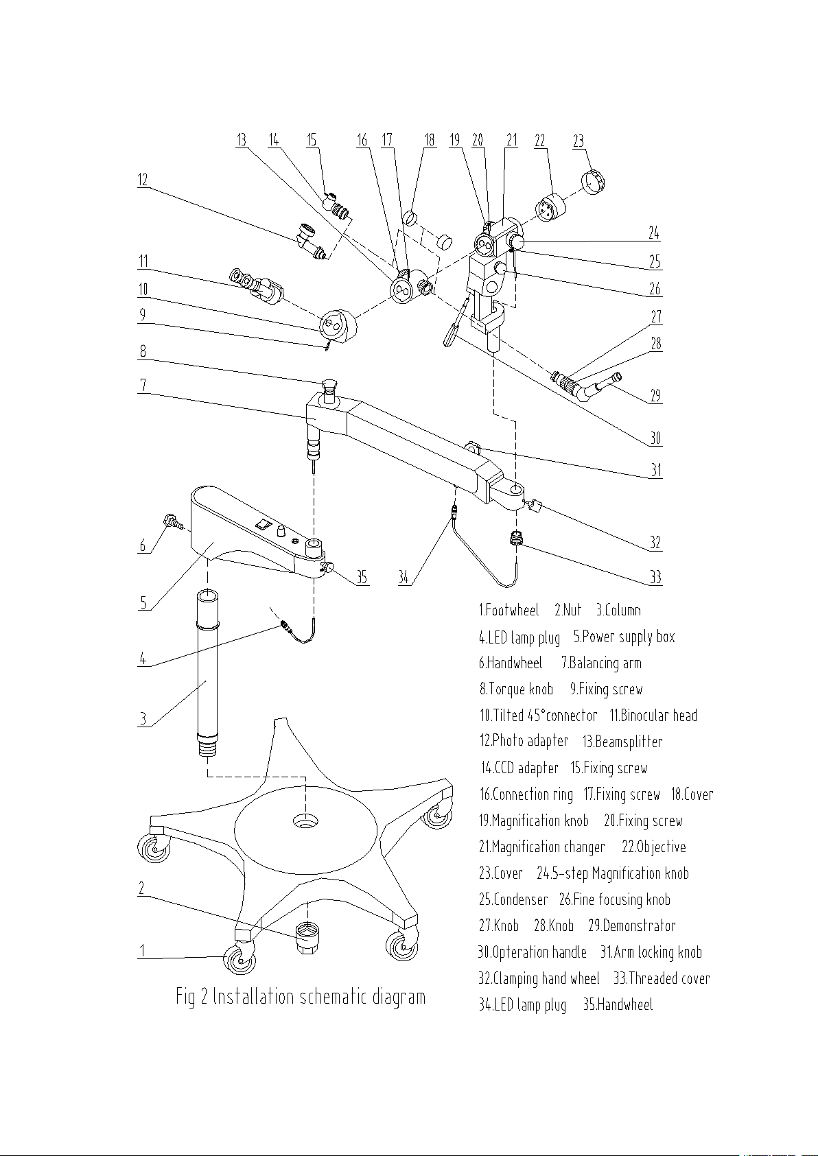
3. Assembly( Fig.2 & Fig.3)
The equipment is packed in two cartons. When carrying and unpacking the cartons, please pay attention to that
the arrow on the carton shall be at upward position. After unpacking the carton, take out all parts one by one
and assemble them according to the following procedures:
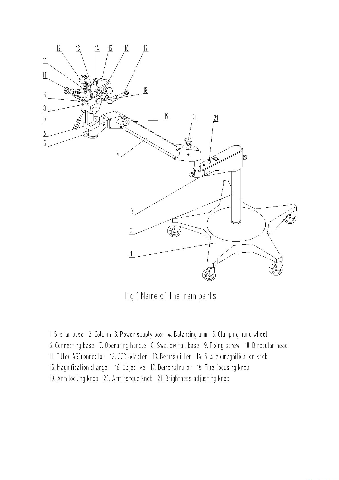
3.1. Assembly of the 5-star base and column
Take out the column (3, Fig.2) and the 5-star base from the package, turn out the nut (2, Fig.2) from the
column, insert the column (3, Fig.2) into the hole of 5-star base, then tighten the nut (2, Fig.2).
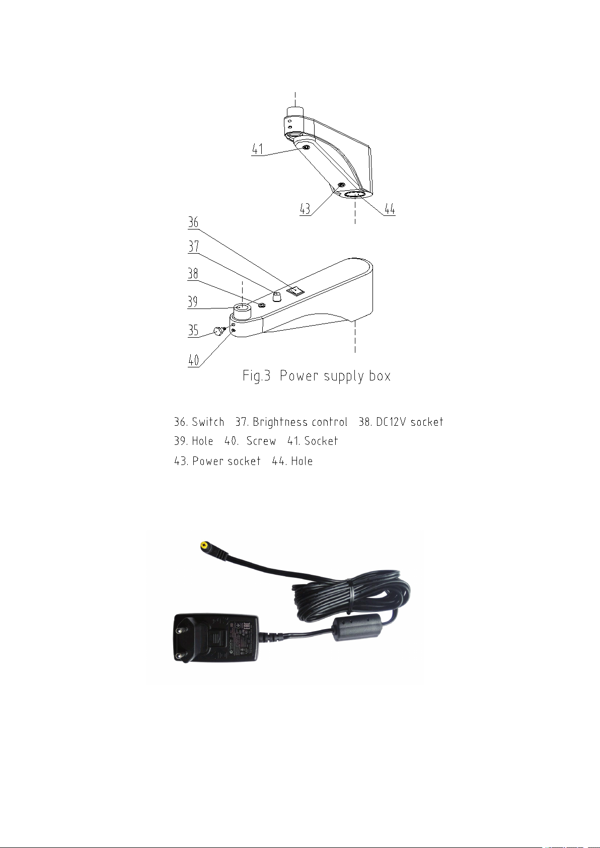
3.2. Assembly of the LED power box
Take out the power supply box (5, Fig.2) from the package, insert it into the column (3, Fig.2), then fix it with
clamping hand wheel (6, Fig.2).
3.3. Assembly of the balancing arm
Take out the balancing arm (7, Fig.2) from the package, insert it into the power box hole (39, Fig.3) and fix it
with clamping hand wheel (35, Fig.2).
3.4. Assembly of the magnification changer (with fine focusing system and connecting base)
Take out the magnification changer (21, Fig.2) from the package, take off the threaded cover (33, Fig.2), insert
it into the hole of arm, then tighten this threaded cover(33, Fig.2)
3.5. Assembly of the beamsplitter, 45° tilted connecting component, CCD camera adaptor, demonstrator,
photo adaptor
Take out the beamsplitter, install it to the magnification changer and fix it with fixing screw (20, Fig.2). Take
out the tilted 45°connector, install it to the beamsplitter and fix it with fixing screw (17, Fig.2). Take out the
CCD (14, Fig.2) or photo (12, Fig.2) adapter, insert it into the any end of the beamsplitter and fix it with the
connecting ring (16, Fig.2) . Take out the demonstrator, insert it into the other end of the beamsplitter and fix it
with the connecting ring (16, Fig.2)
3.6. Assembly of the binocular head
Take out the straight binocular head (11, Fig2) from the package, install it to the tilted 45°connector, then
fasten the fixing screw (9, Fig2).
3.7. Connection of the LED lamp plug
Insert the LED lamp plug(34, Fig.2)into the socket under the arm. Insert the plug (4, Fig.2) into the socket(41,
Fig.3) under the power supply.
3.8. Connection of the power adapter
Insert output connector of power adapter (Fig.4)into the socket (43, Fig.3) under the power supply, connect the
power adapter to power supply.