Allworx 48x User manual

Allworx 48x
Installation Guide

No part of this publication may be reproduced, stored in a retrieval system, or transmitted, in any
form or by any means, electronic, mechanical, photocopy, recording, or otherwise without the prior
written permission of Allworx.
© 2010 Allworx Corp. All rights reserved. Allworx, a wholly owned subsidiary of PAETEC Holding. All other
names may be trademarks or registered trademarks of their respective owners.

48x Server Installation Guide
300 Main Street • East Rochester, NY 14445 • Toll Free 1-866-ALLWORX • 585-421-3850 • www.allworx.com
© 2010 Allworx Corp. All rights reserved. Allworx, a wholly owned subsidiary of PAETEC Holding. All other names may be trademarks or
registered trademarks of their respective owners.
Version:1. Revised: July 15, 2010
Page i
Table of Contents
1Installation Overview.....................................................................................................................................1
2Unpacking .....................................................................................................................................................2
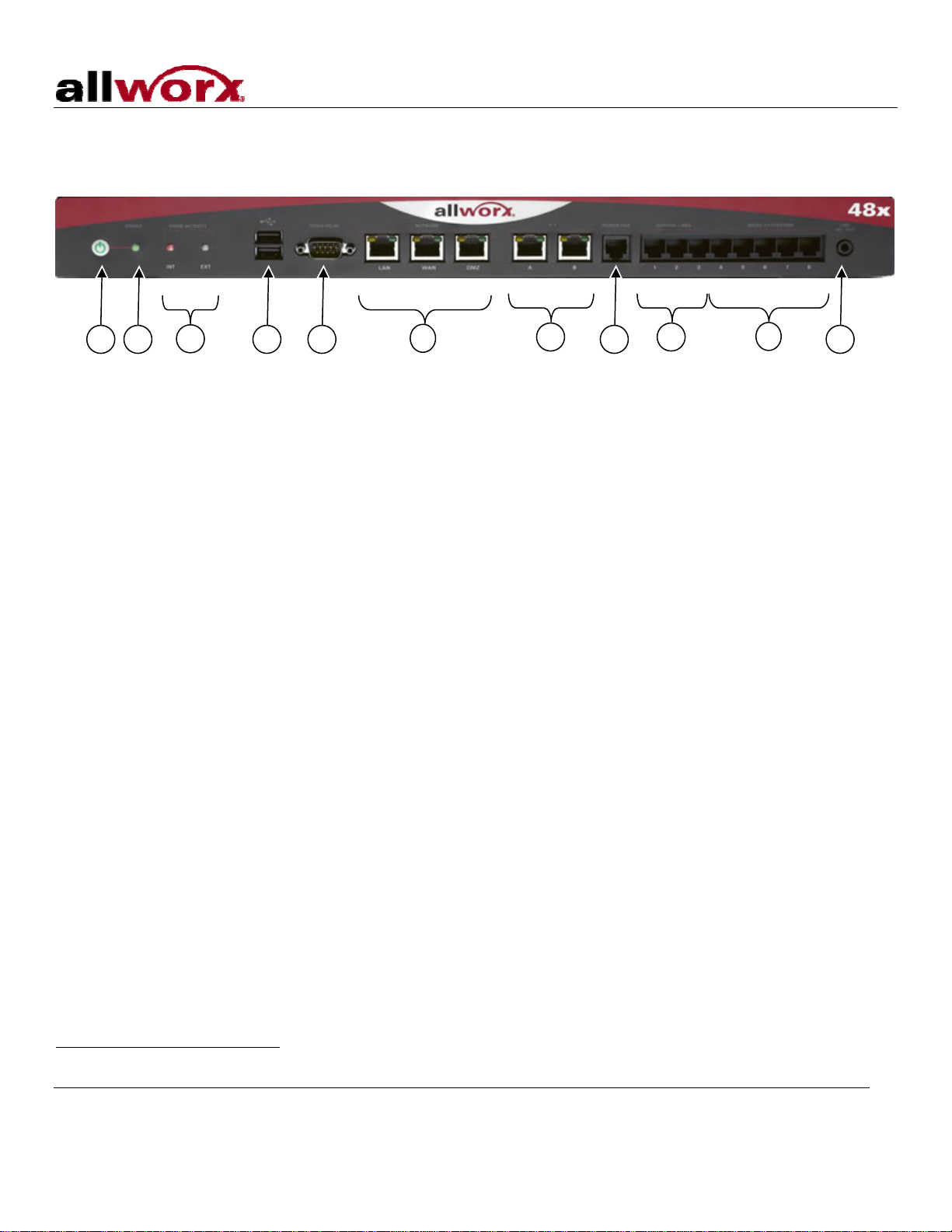
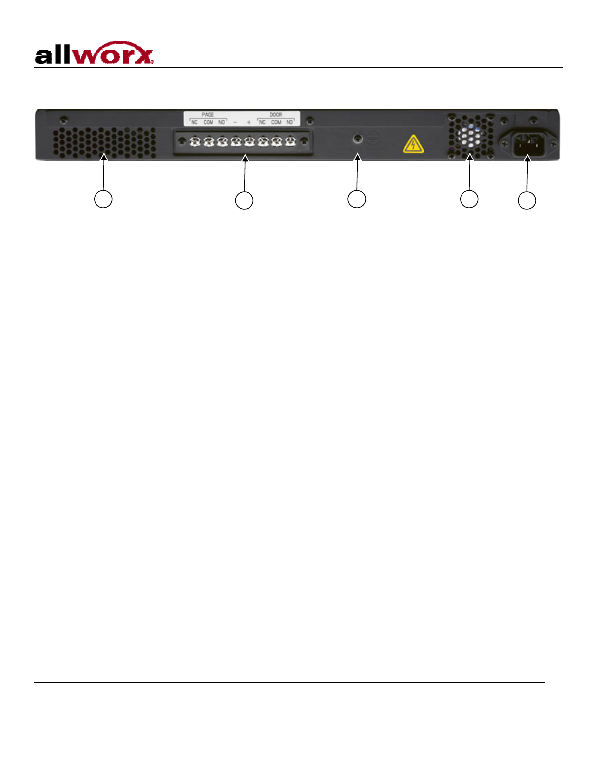
3Chassis Views...............................................................................................................................................3
4Mechanical....................................................................................................................................................5
4.1 Tabletop Placement..............................................................................................................................5
4.2 Rack Mount...........................................................................................................................................5
4.2.1 Consider When Mounting..................................................................................................................6
4.3 Wall Mount............................................................................................................................................7
5Electrical........................................................................................................................................................9
5.1 Power Connection.................................................................................................................................9
5.2 Chassis Ground ....................................................................................................................................9
5.3 Power-Up Sequence.............................................................................................................................9
5.4 Safe Mode Sequence .........................................................................................................................10
6Server Configuration ...................................................................................................................................11
7Ethernet Connectivity..................................................................................................................................12
8Analog Telephony .......................................................................................................................................13
9T1................................................................................................................................................................14
10 Accessories (Optional)................................................................................................................................15
10.1 Line IN/OUT........................................................................................................................................15
10.2 Terminal Block ....................................................................................................................................15
10.3 Serial Port ...........................................................................................................................................15
11 Physical and Environmental Specifications.................................................................................................16
12 Regulatory Notices......................................................................................................................................17
12.1 FCC Part 68........................................................................................................................................17
12.2 Industry Canada..................................................................................................................................17
12.3 Radio and Television Interference ......................................................................................................18

48x Server Installation Guide
300 Main Street • East Rochester, NY 14445 • Toll Free 1-866-ALLWORX • 585-421-3850 • www.allworx.com
© 2010 Allworx Corp. All rights reserved. Allworx, a wholly owned subsidiary of PAETEC Holding. All other names may be trademarks or
registered trademarks of their respective owners.
Version:1. Revised: July 15, 2010
Page ii
- This page intentionally left blank -

48x Server Installation Guide
300 Main Street • East Rochester, NY 14445 • Toll Free 1-866-ALLWORX • 585-421-3850 • www.allworx.com
© 2010 Allworx Corp. All rights reserved. Allworx is a registered trademark of Allworx Corp. All other names may be trademarks or registered
trademarks of their respective owners.
Version: 1. Revised: July 15, 2010
Page 1
1 Installation Overview
Installation of the Allworx®48x involves the following steps:
1. Unpacking
2. Mechanical Installation
3. Electrical Installation
4. Server Configuration
5. Network Installation
6. Telephony Installation
7. T1 Installation
8. Accessories Installation
Each of these steps will be described in the following sections.

48x Server Installation Guide
300 Main Street • East Rochester, NY 14445 • Toll Free 1-866-ALLWORX • 585-421-3850 • www.allworx.com
© 2010 Allworx Corp. All rights reserved. Allworx is a registered trademark of Allworx Corp. All other names may be trademarks or registered
trademarks of their respective owners.
Version: 1. Revised: July 15, 2010
Page 2
2 Unpacking
Open the box and carefully unpack it. Save all shipping and packaging materials. Verify all items against the
parts list shown in Table 1. If any items are missing, contact your dealer or Allworx Customer Support at 866-
255-9679.
Quantity Item Part Number
1 Allworx 48x Server 7502600
1 Power Cord 3000100
1 48x Installation Instructions 5000221
1 Sheet that has 4 Rubber Feet for Table Mounts 4122181
1 Rack and Wall Mount Hardware Kit 4100180
Table 1: Parts List

48x Server Installation Guide
300 Main Street • East Rochester, NY 14445 • Toll Free 1-866-ALLWORX • 585-421-3850 • www.allworx.com
© 2010 Allworx Corp. All rights reserved. Allworx is a registered trademark of Allworx Corp. All other names may be trademarks or registered
trademarks of their respective owners.
Version: 1. Revised: July 15, 2010
Page 3
3 Chassis Views Figure 1: Front Chassis View
1 Power switch
Press & Release – Normal shutdown within a few seconds
Press & Hold – Forced shutdown
2 Power LED – Indicates system start up activity
3 Activity LEDs – Green indicates mounted drive; blinking light indicates activity
4 Two (2) USB Host Ports
5 Door relay port
6 RJ-45 10BaseT/100BaseTX Auto-Sensing Auto-MDI/MDIX Local Area, Wide
Area, and Demilitarized Zone (DMZ)*Network Ethernet ports.
7 T1 Ports (A/B)
8 RJ-11 Power Fail analog phone connector
9 RJ-11 loop-start FXO for central office connection (Ports 1-3)
10 RJ-11 FXS ports for inside extensions (Ports 4-8)
11 3.5 mm stereo audio mini jack for music-on-hold (input) and overhead paging
(output)
*Future Feature
9
67
3214
5
810 11

48x Server Installation Guide
300 Main Street • East Rochester, NY 14445 • Toll Free 1-866-ALLWORX • 585-421-3850 • www.allworx.com
© 2010 Allworx Corp. All rights reserved. Allworx is a registered trademark of Allworx Corp. All other names may be trademarks or registered
trademarks of their respective owners.
Version: 1. Revised: July 15, 2010
Page 4
Figure 2: Rear Chassis View
12 Air intake vent
13 Terminal block for door relay or paging amplifier
14 Permanent ground connecting screw
15 Air exhaust vent
16 IEC Power cord connector
14 15 16
12 13

48x Server Installation Guide
300 Main Street • East Rochester, NY 14445 • Toll Free 1-866-ALLWORX • 585-421-3850 • www.allworx.com
© 2010 Allworx Corp. All rights reserved. Allworx is a registered trademark of Allworx Corp. All other names may be trademarks or registered
trademarks of their respective owners.
Version: 1. Revised: July 15, 2010
Page 5
4 Mechanical
4.1 Tabletop Placement
To install the Allworx 48x on a tabletop or shelf:
1. Remove the four rubber feet from the packaging.
2. Remove the paper backing from each rubber foot.
3. Turn over the chassis and place one foot at each corner on the bottom of the chassis.
4.2 Rack Mount
To mount the Allworx 48x, 1U high rack mount, inside of a standard 19 inch rack:
1. Verify that there is sufficient clearance around the server’s front and rear panels to allow power, network,
and telephony connections.
2. Place the brackets so that the smaller face of the bracket extends away from the front of the unit to
accommodate installation into the rack (See Figure 3).
3. Install the mounting brackets on each side of the server chassis using the four 6-32 flat head screws.
4. Proceed to the Power Connection (Section 5.1) instructions and perform the steps appropriate for your
installation before placing the system into the rack.
5. Install the server into the rack using appropriate hardware.
Figure 3: Rack Mount Bracket Installation

48x Server Installation Guide
300 Main Street • East Rochester, NY 14445 • Toll Free 1-866-ALLWORX • 585-421-3850 • www.allworx.com
© 2010 Allworx Corp. All rights reserved. Allworx is a registered trademark of Allworx Corp. All other names may be trademarks or registered
trademarks of their respective owners.
Version: 1. Revised: July 15, 2010
Page 6
4.2.1 Consider When Mounting
•Elevated Operating Ambient - If installed in a closed or multi-unit rack assembly, the operating ambient
temperature of the rack environment may be greater than room ambient. Therefore, consideration
should be given to installing the equipment in an environment compatible with the maximum ambient
temperature (40°C).
•Reduced Air Flow - Installation of the equipment in a rack should be such that the amount of air flow
required for safe operation of the equipment is not compromised.
•Mechanical Loading - Mounting of the equipment in the rack should be such that a hazardous condition
is not achieved due to uneven mechanical loading.
•Circuit Overloading - Consideration should be given to the connection of the equipment to the supply
circuit and the effect that overloading of the circuits might have on overcurrent protection and supply
wiring. Appropriate consideration of equipment nameplate ratings should be used when addressing this
concern.
•Reliable Earthing - Reliable earthing of rack-mounted equipment should be maintained. Particular
attention should be given to supply connections other than direct connections to the branch circuit (e.g.
use of power strips).

48x Server Installation Guide
300 Main Street • East Rochester, NY 14445 • Toll Free 1-866-ALLWORX • 585-421-3850 • www.allworx.com
© 2010 Allworx Corp. All rights reserved. Allworx is a registered trademark of Allworx Corp. All other names may be trademarks or registered
trademarks of their respective owners.
Version: 1. Revised: July 15, 2010
Page 7
4.3 Wall Mount
Note: For wall mount installations, discard included power cord and use only a UL listed power cord of type
SJ or SO or better.
To mount the Allworx 48x on ½” drywall:
1. Verify that there is sufficient clearance around the server’s front and rear panels to allow power, network,
and telephony connections. Place the brackets on each side of the unit so that the smaller face of the L-
Bracket is facing down (See Figure 4).
2. Install the mounting brackets on each side of the server chassis using the four 6-32 flat head screws.
3. Use 50lb self-drilling drywall anchors rated for at least 20 lbs with screws that are either #6 or #8. Locate
two anchors that will support the upper end of the unit using the wall mount diagram. Install the anchors
per the anchor manufacturer’s recommendation. Install the mounting screws through the bracket holes
and into the anchors.
4. Tighten screws so that Allworx server is secured firmly against the wall.
Caution: The Allworx server must be securely mounted to the wall to avoid equipment damage or
personal injury.
Note: The unit must be mounted with the front facing left or right, not up or down (See Figure 5).
Figure 4: Wall Mount Bracket Installation

48x Server Installation Guide
300 Main Street • East Rochester, NY 14445 • Toll Free 1-866-ALLWORX • 585-421-3850 • www.allworx.com
© 2010 Allworx Corp. All rights reserved. Allworx is a registered trademark of Allworx Corp. All other names may be trademarks or registered
trademarks of their respective owners.
Version: 1. Revised: July 15, 2010
Page 8
Figure 5: Wall Mount Orientation
Correct Orientation Wrong Orientation

48x Server Installation Guide
300 Main Street • East Rochester, NY 14445 • Toll Free 1-866-ALLWORX • 585-421-3850 • www.allworx.com
© 2010 Allworx Corp. All rights reserved. Allworx is a registered trademark of Allworx Corp. All other names may be trademarks or registered
trademarks of their respective owners.
Version: 1. Revised: July 15, 2010
Page 9
5 Electrical
5.1 Power Connection
Warning: Failure to follow these steps may result in equipment damage, personal injury, and a voided
product warranty.
Insert the female end of the power cord into the receptacle on the rear of the unit. Connect the other end to
the power source. The product is rated 115/230 VAC, 1/0.7A, and 50/60Hz. The Allworx server will
automatically begin to power up once the power has been stable for a few seconds. This is part of the design
to automatically boot up after a power failure.
5.2 Chassis Ground
Warning: Failure to follow these steps may result in equipment damage, personal injury, and a voided
product warranty.
To help prevent electrical shock, the separate protective earthing terminal, located next to the power jack on
the rear panel, must be permanently connected to earth using 18 AWG wire or larger. (See Figure 2, item 14)
5.3 Power-Up Sequence
As the Allworx server progresses through the power up sequence, the front panel lights will respond as shown
in Table 2.
Front Panel Light Power-Up Sequence Description
Power Flashes green as the power up sequence
progresses; steady green when the unit is ready.
Activity – INT Solid green when internal drive mounted; blinking
light indicates activity.
Activity – EXT
Solid green when USB device attached and enabled;
blinking light indicates activity.
Table 2: Front Panel Lights During Power-Up Sequence

48x Server Installation Guide
300 Main Street • East Rochester, NY 14445 • Toll Free 1-866-ALLWORX • 585-421-3850 • www.allworx.com
© 2010 Allworx Corp. All rights reserved. Allworx is a registered trademark of Allworx Corp. All other names may be trademarks or registered
trademarks of their respective owners.
Version: 1. Revised: July 15, 2010
Page 10
5.4 Safe Mode Sequence
With the unit powered off, press and hold the power button for more than 1 second. Release the power button
once the power light turns amber. As it progresses through the safe mode power up sequence, the front panel
lights will respond as shown in Table 3.
Front Panel Light Power-Up Sequence Description
Power
Turns amber to indicate a safe mode boot has
been initialized; Flashes green as the power up
sequence progresses; Steady amber when the
unit is in safe mode.
Activity – INT Off
Table 3: Front Panel Lights During Safe Mode Sequence

48x Server Installation Guide
300 Main Street • East Rochester, NY 14445 • Toll Free 1-866-ALLWORX • 585-421-3850 • www.allworx.com
© 2010 Allworx Corp. All rights reserved. Allworx is a registered trademark of Allworx Corp. All other names may be trademarks or registered
trademarks of their respective owners.
Version: 1. Revised: July 15, 2010
Page 11
6 Server Configuration
The Allworx 48x provides an administrative interface to configure and administer the server. The administrative
interface is accessed using a web browser. Assuming the network settings are set to their factory defaults, the
steps to connect to this interface are:
1. Plug your PC into the server’s LAN port.
2. Set up the PC’s network interface to obtain an IP address automatically (using DHCP).
3. Verify that the PC has an IP address on the 192.168.2.x network. You may need to release and renew the
PC’s IP address to get an address from the server.
4. Open your browser and enter the URL of http://192.168.2.254:8080.
5. When the “Welcome to Allworx” page appears, login using the default password: admin.
When the Home page appears, click on the Install Checklist link (on the left hand side) to bring up a new
window containing steps necessary to set up a new system. Each brief step description is followed by a link to
get to the appropriate administrative web page to execute the step. These steps are ordered to aid in a
successful configuration. Most of the web pages used to execute each step contain detailed feature
descriptions and help instructions that are required to carry out the step. Use the Allworx System
Administrator’s Guide** as a supplement for the information on the web pages when necessary.
If the server has been previously configured for another installation, you should restore it to its factory default
configuration. This can be done by:
1. Rebooting the server to Safe Mode by holding down the power button when the server is off, or selecting
Maintenance / Restart, and Enter Safe Mode after restart.
2. Format the disk and perform a Software Update (See Allworx System Administrator’s Guide** for
instructions).
** Allworx System Administrator’s Guide for the can be found at www.allworx.com

48x Server Installation Guide
300 Main Street • East Rochester, NY 14445 • Toll Free 1-866-ALLWORX • 585-421-3850 • www.allworx.com
© 2010 Allworx Corp. All rights reserved. Allworx is a registered trademark of Allworx Corp. All other names may be trademarks or registered
trademarks of their respective owners.
Version: 1. Revised: July 15, 2010
Page 12
7 Ethernet Connectivity
The Local Area Network (LAN), Wide Area Network (WAN), and Demilitarized Zone (DMZ)* data network ports
are 10BaseT/100BaseTX auto-sensing and auto-MDI/MDIX ports.
SIP phones connect to the server just as any other data network device. The phones and the server need to be
properly configured. See the Server Configuration (Section 6) for more information.
The Allworx 48x is a sophisticated network appliance that must be properly configured before being connected
to the LAN, WAN, and DMZ*.
Note: Do not plug any network or ISP service into the server without first properly configuring the server.
Failure to heed this warning may result in a disruption of network connectivity with other equipment on
the network.
After the unit is properly configured, the LAN, WAN, and DMZ*network infrastructure cables can be plugged
in. Standard RJ-45 category 5 network cables must be used.
The LED’s on the LAN, WAN, and DMZ*ports are defined in Table 4.
LED Identification State Description
Off No link: the network is not connected
On Link: the network is successfully connected
Green Blinking Activity: data is being transmitted or received
Off Speed: 10MB/S
Amber On Speed: 100MB/S
Table 4: Network Port LED Definitions
*Future Feature

48x Server Installation Guide
300 Main Street • East Rochester, NY 14445 • Toll Free 1-866-ALLWORX • 585-421-3850 • www.allworx.com
© 2010 Allworx Corp. All rights reserved. Allworx is a registered trademark of Allworx Corp. All other names may be trademarks or registered
trademarks of their respective owners.
Version: 1. Revised: July 15, 2010
Page 13
8 Analog Telephony
Caution: To reduce the risk of fire, use only 26 AWG (or larger) UL listed or CSA certified
telecommunications line cord.
The server’s analog phone connections can be used to connect Central Office (CO) lines or telephone
handsets. Table 5 below describes the ports:
RJ-11 Ports Type Description
1-3 FXO (loop-start) Used to connect to Central Office (CO) lines
4-8 FXS Telephone handsets
Table 5: Analog Telephony Ports
It is recommended that the ports be connected as follows:
•CO Lines: Begin with port 1 and move up.
•Telephone Handsets: Begin with port 8 and move down.
The Power Fail Phone port may be used to connect an analog phone device that is operational in the event
that the server loses power or fails. During power failure, it automatically connects to the first outside phone
line port (port 1).
Surge protection is provided internally on all telephony interfaces.

48x Server Installation Guide
300 Main Street • East Rochester, NY 14445 • Toll Free 1-866-ALLWORX • 585-421-3850 • www.allworx.com
© 2010 Allworx Corp. All rights reserved. Allworx is a registered trademark of Allworx Corp. All other names may be trademarks or registered
trademarks of their respective owners.
Version: 1. Revised: July 15, 2010
Page 14
9 T1
T1-A and T1-B interface pin-outs for typical service connections as shown in Table 6, may require either a
straight through cable or a cross-over cable.
Pin Description
1 Receive (ring)
2 Receive (tip)
3 Not Used
4 Transmit (ring)
5 Transmit (tip)
6 Not Used
7 Not Used
8 Not Used
Table 6: T1 Connector Wiring
The Allworx 48x is designed for T1 “short haul” use and has a fully integrated Channel Service Unit / Data
Service Unit (CSU/DSU). An external CSU/DSU is not required and should not be used. The Allworx 48x
should be connected directly to the on-site smart jack or local T1 device using the proper cabling. Do not
connect the Allworx 48x directly to the "long haul" wire pairs exiting the building.
Note: Do not plug any network or ISP service into the server without first properly configuring the server.
Failure to heed this warning may result in a disruption of network connectivity with other equipment on
the network.
After the unit is properly configured, the T1 network infrastructure cables can be plugged in. Standard RJ-45
T1 cables must be used.
The LED’s on the T1 ports are defined in Table 7.
Green Amber State Meaning
OFF OFF Red Alarm State – No received Signal
ON OFF No Alarms or Errors – Good Lock to Line
ON ON Amber Alarm State – Remote End error
ON Blinking Signal Quality Problem – Error of some kind
Table 7: Network Port LED Definitions

48x Server Installation Guide
300 Main Street • East Rochester, NY 14445 • Toll Free 1-866-ALLWORX • 585-421-3850 • www.allworx.com
© 2010 Allworx Corp. All rights reserved. Allworx is a registered trademark of Allworx Corp. All other names may be trademarks or registered
trademarks of their respective owners.
Version: 1. Revised: July 15, 2010
Page 15
10 Accessories (Optional)
10.1 Line IN/OUT
Connect the output from your music and paging system to the server using a Y-Adapter Audio Cable (See
Figure 6). Insert the 3.5mm stereo plug (See Figure 7) into the audio connector labeled Line IN/OUT on the
front panel (See Figure 1 item 11). A stereo splitter (not included) is required to use both Music-On-Hold and
Overhead Paging collectively.
Note: The white audio channel is used for music input and the red audio channel is used for paging output
(See Figure 6).
Figure 6: Y-Adapter Audio Cable Figure 7: Audio Plug Diagram
10.2 Terminal Block
The unit comes with two (2) sets of C-form relay contacts for connecting to external devices such as remote
door releases and paging amplifiers. The contacts are rated 30 VDC @1A. Only connect the SELV circuits
meeting IEC 60950-1 / UL 60950-1 OR NEC Class 2 circuits. Loop the bare wires of the paging amplifier
and/or door relay to the devices corresponding screws (NC, COM, NO) on the terminal block, and then tighten
the screws with a screw driver. Additional audio output for paging can be added using the -/+ screws (See
Figure 2, item 13).
10.3 Serial Port
In addition to the contacts on the rear terminal block, door relay contacts are available at the serial port
connector on the front of the unit (See Figure 1, item 5). The contacts are rated 30 VDC @ 1A. Only connect
SELV circuits meeting IEC 60950-1 / UL 60950-1 OR NEC Class 2 circuits.
Warning: Do not exceed the contact rating.
The connector is shared with the serial port (See Figure 1, item 5). The pin-out is shown in Table 8 below.
Pin Signal Direction
2 (do not connect) RX Input
3 (do not connect) TX Output
5 (do not connect) GND --
9 Relay COM --
Line In
GND

48x Server Installation Guide
300 Main Street • East Rochester, NY 14445 • Toll Free 1-866-ALLWORX • 585-421-3850 • www.allworx.com
© 2010 Allworx Corp. All rights reserved. Allworx is a registered trademark of Allworx Corp. All other names may be trademarks or registered
trademarks of their respective owners.
Version: 1. Revised: July 15, 2010
Page 16
6 Relay NC --
1 Relay NO --
Table 8: Door Relay Pin-Out
11 Physical and Environmental Specifications
Dimensions (W x H x D) 17 x 1.75 x 10 inches (43.2 x 4.4 x 25.4 cm)
Weight (Base Model) 7.5 lbs
Power 115/230 VAC, 1/0.7A, 50/60Hz
Temperature 0°~ 40°C
Humidity 15%~ 90%RH, Non-condensing
Table 9: Specifications
Table of contents
Other Allworx Telephone manuals

Allworx
Allworx 6x Installation guide

Allworx
Allworx 9202 User manual

Allworx
Allworx 9212 User manual

Allworx
Allworx 9204 User manual

Allworx
Allworx 24x User manual

Allworx
Allworx 9224 User manual

Allworx
Allworx 9224 User manual

Allworx
Allworx 9204 User manual

Allworx
Allworx 9202E User manual

Allworx
Allworx 9202E User manual