Alpha Outback Energy SPCIIIS-5000-48 User manual

User Manual
SPCIIIS-5000-48
5kW with MPPT Solar Charger
Inverter/Charger
Version: 1.3

0
Table of Contents
ABOUT THIS MANUAL ......................................................................................................................................1
Purpose ................................................................................................................................................1
Scope ...................................................................................................................................................1
SAFETY INSTRUCTIONS...................................................................................................................................1
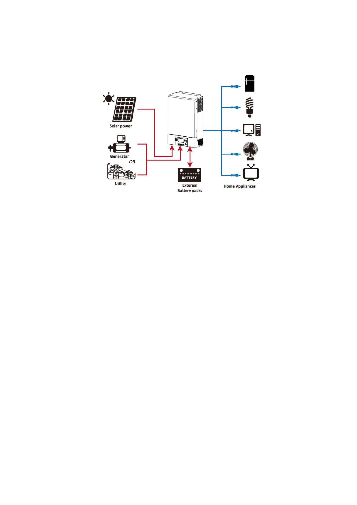
INTRODUCTION.................................................................................................................................................2
Product Overview ..................................................................................................................................3
INSTALLATION...................................................................................................................................................4
Unpacking and Inspection ......................................................................................................................4
Preparation ...........................................................................................................................................4
Mounting the Unit..................................................................................................................................4
Battery Connection ................................................................................................................................5
AC Input/Output Connection ..................................................................................................................6
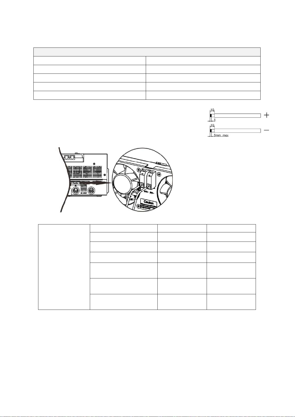
PV Connection.......................................................................................................................................7
Final Assembly ......................................................................................................................................9
Remote Display Panel Installation .........................................................................................................10
Communication Connection ................................................................................................................101
Dry Contact Signal...............................................................................................................................12
BMS Communication ............................................................................................................................12
OPERATION......................................................................................................................................................13
Power ON/OFF ....................................................................................................................................13
Operation and Display Panel.................................................................................................................13
LCD Display Icons................................................................................................................................14
LCD Setting.........................................................................................................................................16
Display Setting ....................................................................................................................................28
Operating Mode Description .................................................................................................................34
Faults Reference Code .........................................................................................................................36
Warning Indicator................................................................................................................................37
BATTERY EQUALIZATION ..............................................................................................................................38
SPECIFICATIONS.............................................................................................................................................40
Table 1 Line Mode Specifications ..........................................................................................................40
Table 2 Inverter Mode Specifications.....................................................................................................41
Table 3 Charge Mode Specifications ......................................................................................................42
Table 4 General Specifications ..............................................................................................................42
Table 5 Parallel Specifications ............................................................................................................. 423
TROUBLE SHOOTING.....................................................................................................................................44
Appendix I: Parallel function..........................................................................................................................45
Appendix II: BMS Communication Installation.............................................................................................62
Appendix III: Approximate Back-up Time Table ...........................................................................................68

1
ABOUT THIS MANUAL
Purpose
This manual describes the assembly, installation, operation and troubleshooting of this unit. Please read
this manual carefully before installations and operations. Keep this manual for future reference.
Scope
This manual provides safety and installation guidelines as well as information on tools and wiring.
SAFETY INSTRUCTIONS
WARNING: This chapter contains important safety and operating instructions. Read and
keep this manual for future reference.
1. Before using the unit, read all instructions and cautionary markings on the unit, the batteries and all
appropriate sections of this manual.
2. CAUTION --To reduce risk of injury, charge only deep-cycle lead acid type rechargeable batteries. If
other types batteries are used, follow the manufacturer’s instructions carefully.
3. Do not disassemble the unit. Take it to a qualified service center when service or repair is required.
Incorrect re-assembly may result in a risk of electric shock or fire.
4. To reduce risk of electric shock, disconnect all wirings before attempting any maintenance or cleaning.
Turning off the unit will not reduce this risk.
5. CAUTION –Only qualified personnel can install this device with battery.
6. NEVER charge a frozen battery.
7. For optimum operation of this inverter/charger, please follow required spec to select appropriate cable
size. It’s very important to correctly operate this inverter/charger.
8. Be very cautious when working with metal tools on or around batteries. A potential risk exists to drop
a tool to spark or short circuit batteries or other electrical parts and could cause an explosion.
9. Please strictly follow installation procedure when you want to disconnect AC or DC terminals. Please
refer to INSTALLATION section of this manual for the details.
10. Fuses are provided as over-current protection for the battery supply.
11. GROUNDING INSTRUCTIONS -This inverter/charger should be connected to a permanent grounded
wiring system. Be sure to comply with local requirements and regulation to install this inverter.
12. NEVER cause AC output and DC input short circuited. Do NOT connect to the mains when DC input
short circuits.
13. Warning!! Only qualified service persons are able to service this device. If errors still persist after
following troubleshooting table, please send this inverter/charger back to local dealer or service center
for maintenance.

2
INTRODUCTION
This off-grid PV inverter can provide power to connected loads by utilizing PV power, utility power and battery
power.
Figure 1 Basic PV System Overview
Depending on different power situations, this inverter is designed to generate continuous power from PV solar
modules (solar panels), battery, and the utility. When MPP input voltage of PV modules is within acceptable
range (see specification for the details), this inverter is able to generate power to offset the grid (utility) and
charge battery. The galvanic isolation between Battery and AC output, allow the user to use any battery
grounding schema with this hybrid inverter. See Figure 1 for a simple diagram of a typical solar system with this
inverter.

3
Product Overview
NOTE: For parallel mode installation and operation please check
Appendix I
.
1. LCD display
2. Status indicator
3. Charging indicator
4. Fault indicator
5. Function buttons
6. Power on/off switch
7. AC input connectors
8. AC output connectors (Load connection)
9. PV connectors
10. Battery connectors
11. Circuit breaker
12. Current sharing port
13. Parallel communication port
14. Dry contact
15. USB port: for communication port and USB function port
16. LED indicators for USB function setting / Charger source priority setting
17. BMS communication port: CAN, RS-485 or RS-232
18. RS-232 communication port

4
INSTALLATION
Unpacking and Inspection
Before installation, please inspect the unit. Be sure that nothing inside the package is damaged. You should
have received the following items inside of package:
Inverter unit Software CD Manual RS-232 cable Parallel communication cable Current sharing cable
NOTE: Parallel communication cable and Current sharing cable are only used for parallel mode installation.
Follow instructions in
Appendix I
to install a system with multiple units.
Preparation
Before connecting all wirings, please take off bottom cover by removing two screws as shown below.
WARNING! Make sure not to damage / disconnect the cables that link the cover with the inverter case.
Mounting the Unit
Consider the following points before selecting where to install:
Do not mount the inverter on flammable construction materials.
Mount on a solid surface
Install this inverter at eye level in order to allow the LCD display to
be read at all times.
The ambient temperature should be between 0°C and 55°C to
ensure optimal operation.
The recommended installation position is to be adhered to the wall
vertically.
Be sure to respect the clearances shown in the diagram at the right
to guarantee sufficient heat dissipation and to have enough space
for removing wires.
SUITABLE FOR MOUNTING ON CONCRETE OR OTHER
NON-COMBUSTIBLE SURFACE ONLY.

5
Install the unit by screwing three screws. It’s recommended to use M4 or M5 screws.
Battery Connection
CAUTION: For safety operation and regulation compliance, it’s requested to install a separate DC over-current
protector or disconnect device between battery and inverter. It may not be required to have a disconnect
device in some applications, however, it’s still required to have over-current protection installed. Please refer to
typical amperage in below table as required fuse or breaker size.
WARNING! All wiring must be performed by a qualified personnel.
WARNING! It's very important for system safety and efficient operation to use
appropriate cable for battery connection. To reduce risk of injury, please use the
proper recommended cable and terminal size as below.
Recommended battery cable and terminal size:
Typical
Amperage
Battery
Capacity
AWG no.
Section
Ring Terminal
Torque
Value
Inner section
Dimensions
D (mm)
L (mm)
135 A
200 Ah
2x 4 AWG
50 mm2
50 mm2
6.4
49.7
2~3 Nm
Please follow below steps to implement battery connection:
1. Assemble battery ring terminal based on recommended battery cable and terminal size.
2. Insert the ring terminal of battery cable flatly into battery connector of inverter and make sure the nuts are
tightened with torque of 2-3 Nm. Make sure polarity at both the battery and the inverter/charge is correctly
connected and ring terminals are tightly screwed to the battery terminals.
Ring terminal:

6
WARNING: Shock Hazard
Installation must be performed with care due to high battery voltage in series.
CAUTION!! Do not place anything between the flat part of the inverter terminal and the ring
terminal. Otherwise, overheating may occur.
CAUTION!! Do not apply anti-oxidant substance on the terminals before terminals are connected
tightly.
CAUTION!! Before making the final DC connection or closing DC breaker/disconnector, be sure
positive (+) must be connected to positive (+) and negative (-) must be connected to negative (-).
AC Input/Output Connection
CAUTION!! Before connecting to AC input power source, please install a separate AC breaker between
inverter and AC input power source. This will ensure the inverter can be securely disconnected during
maintenance and fully protected from over current of AC input.
CAUTION!! There are two terminal blocks with “IN” and “OUT” markings. ENSURE that utility AC input is
connected to IN and load AC to OUT and not the wrong way round and also that Line and Neutrals are
connected correctly.
WARNING! All wiring must be performed by a qualified personnel.
WARNING! It's very important for system safety and efficient operation to use appropriate cable for AC input
connection. To reduce risk of injury, please use the proper recommended cable size as below.
Suggested cable requirement for AC wires
AWG no.
Section
Torque Value
10 AWG
6 mm2
1.2~ 1.6 Nm
Please follow below steps to implement AC input/output connection:
1. Before making AC input/output connection, be sure to open DC protector or disconnector first.
2. Remove insulation sleeve 10mm for six conductors. And shorten phase L and neutral conductor N 3 mm.
3. Insert AC input wires according to polarities indicated on terminal block and tighten the terminal screws. Be
sure to connect PE protective conductor ( ) first.
→Ground (yellow-green)
L→LINE (brown or black)
N→Neutral (blue)
WARNING:
Be sure that AC power source is disconnected before attempting to hardwire it to the unit.

7
4. Insert AC output wires according to polarities indicated on terminal block and tighten terminal screws. Be
sure to connect PE protective conductor ( ) first.
→Ground (yellow-green)
L→LINE (brown or black)
N→Neutral (blue)
5. Make sure the wires are securely connected.
PV Connection
CAUTION: Before connecting to PV modules, please install separately a DC circuit breaker between inverter
and PV modules.
CAUTION: Please install a surge protection device between inverter and PV modules. The recommended
voltage is 500Vdc.
WARNING! Do switch off the inverter before connecting to PV modules. Otherwise, it will cause inverter
damage.
WARNING! Do NOT connect negative or positive terminal of PV modules to the ground.
WARNING! All wiring must be performed by a qualified personnel.
WARNING! It's very important for system safety and efficient operation to use appropriate cable for PV
module connection. To reduce risk of injury, please use the proper recommended cable size as below.
Typical Amperage
AWG no.
Section
Torque
18 A
12 AWG
4 mm2
1.2~1.6 Nm
CAUTION: Important
Be sure to connect AC wires with correct polarity. Reversed L and N wires may cause a short-circuit when these
inverters operate in parallel.
CAUTION: Appliances such as air conditioner are required at least 2~3 minutes to restart because it’s required
to have enough time to balance refrigerant gas inside of circuits. If a power shortage occurs and recovers in a
short time, it will cause damage to your connected appliances. To prevent this kind of damage, please check
manufacturer of air conditioner if it’s equipped with time-delay function before installation. Otherwise, this
inverter/charger will trigger overload fault and cut off output to protect your appliance but sometimes it still
causes internal damage to the air conditioner.

8
PV Module Selection:
When selecting proper PV modules, please be sure to consider below parameters:
1. Open circuit Voltage (Voc) of PV modules not exceeds max. PV array open circuit voltage of inverter.
2. Open circuit Voltage (Voc) of PV modules should be higher than min. battery voltage.
Solar Charging Mode
Max. PV Array Peak Power
5 kWp
Max. PV Array Open Circuit Voltage
450 Vdc
PV Array MPPT Voltage Range
120~430 Vdc
Start-up Voltage
150Vdc +/- 10Vdc
Number of MPPTs
1
Please follow below steps to implement PV module connection:
1. Remove insulation sleeve 10 mm for positive and negative conductors.
2. Check correct polarity of connection cable from PV modules and PV input
connectors. Then, connect positive pole (+) of connection cable to positive
pole (+) of PV input connector. Connect negative pole (-) of connection
cable to negative pole (-) of PV input connector.
Recommended PV module Configuration
PV Module Spec.
(reference)
- 250 Wp
- Vmp: 30.7 Vdc
- Imp: 8.15 Adc
- Voc: 37.4 Vdc
- Isc: 8.63 Adc
- Cells: 60
Total solar input power
Solar input
Q'ty of modules
1500 Wp
6 pieces in series
6 pcs
2000 Wp
8 pieces in series
8 pcs
2750 Wp
11 pieces in series
11 pcs
3000 Wp
6 pieces in series
2 strings in parallel
12 pcs
4000 Wp
8 pieces in series
2 strings in parallel
16 pcs
5000 Wp
10 pieces in series
2 strings in parallel
20 pcs

9
Final Assembly
After connecting all wirings, please put bottom cover back by screwing two screws as shown below.

10
Remote Display Panel Installation
The LCD panel can be removable and installed in a remote site with an optional communication cable. Please
follow below steps to implement this remote panel installation.
Step 1. Loosen the screw on the bottom of LCD panel and push down the panel from the bottom case. Then,
pull out the cable from the remote communication port. Be sure to screw back the fixing plate to the inverter.
Step 2. Drill two holes in the marked locations with two screws as shown below chart. Place the panel on the
surface and align the mounting holes with the two screws. Then, use one more screw on the top to fix the panel
to the wall and check if the remote panel is firmly secured.
Note: Installation to the wall should be implemented
with the proper screws. Refer chart for recommended
spec of screws.
M3
Ø5-Ø9

11
Step 3. Connect LCD panel to the inverter with an optional RJ45 communication cable as below chart.
Communication Connection
Serial Connection
Please use supplied communication cable to connect to inverter and PC. Insert bundled CD into a computer and
follow on-screen instruction to install the monitoring software. For the detailed software operation, please
check user manual of software inside of CD.
Bluetooth Connection
This unit is equipped with a Bluetooth transmitter. Download “WatchPower” APP from Google Play or Google
Store. Once the APP is download, you may connect “WatchPower” APP to your inverter with the password
“123456”. The communication distance is roughly 6 ~ 7 meters.
BMS communication
USB communication
To PC
RS-232 communication
To PC
Remote
communication

12
Dry Contact Signal
There is one dry contact (3A/250VAC) available on the bottom of the display panel. It could be used to deliver
signal to external device when battery voltage reaches warning level.
Unit Status
Condition
Dry contact port:
NC & C
NO & C
Power Off
Unit is off and no output is powered.
Close
Open
Power On
Output is powered from Utility.
Close
Open
Output is
powered
from
Battery or
Solar.
Program 01
set as SUb
or USb
Battery voltage < Low DC warning
voltage
Open
Close
Battery voltage > Setting value in
Program 13 or battery charging
reaches floating stage
Close
Open
Program 01
is set as
SbU
Battery voltage < Setting value in
Program 12
Open
Close
Battery voltage > Setting value in
Program 13 or battery charging
reaches floating stage
Close
Open
BMS Communication
It is recommended to purchase a special communication cable (P/N SPC-COMM) if you are connecting to
Lithium-Ion battery banks. Please refer to Appendix II- BMS Communication Installation for details.

13
OPERATION
Power ON/OFF
Once the unit has been properly installed and the batteries are connected well, simply press On/Off switch
(located on the display panel) to turn on the unit.
Operation and Display Panel
The operation and display panel, shown in below chart, is on the front panel of the inverter. It includes six
indicators, six function keys, on/off switch and a LCD display, indicating the operating status and input/output
power information.
LCD display
Indicators
LED Indicator
Color
Solid/Flashing
Messages
Setting LED 1
Green
Solid On
Output powered by utility
Setting LED 2
Green
Solid On
Output powered by PV
Setting LED 3
Green
Solid On
Output powered by battery
Status
indicators
Green
Solid On
Output is available in bypass mode
Flashing
Output is powered by battery in inverter mode
Green
Solid On
Battery is fully charged
Flashing
Battery is charging.
Red
Solid On
Fault mode
Flashing
Warning mode
Status
indicators
Function keys
On/off switch
Function keys
Setting LED 3
Setting LED 1
Setting LED 2

14
Function Keys
Function Key
Description
ESC
Exit the setting
USB function setting
Select USB OTG functions
Timer setting for the
Output source priority
Setup the timer for prioritizing the output source
Timer setting for the
Charger source priority
Setup the timer for prioritizing the charger source
Up
To last selection
Down
To next selection
Enter
To confirm/enter the selection in setting mode
LCD Display Icons
Icon
Function description
Input Source Information
Indicates the AC input.
Indicates the PV input
Indicate input voltage, input frequency, PV voltage, charger current,
charger power, battery voltage.
Configuration Program and Fault Information
Indicates the setting programs.
Indicates the warning and fault codes.
Warning: flashing with warning code.
Fault: lighting with fault code
Output Information
Indicate output voltage, output frequency, load percent, load in VA, load
in Watt and discharging current.
Battery Information
Indicates battery level by 0-24%, 25-49%, 50-74% and 75-100% in
battery mode and charging status in line mode.
In AC mode, it will present battery charging status.
Status
Battery voltage
LCD Display
Constant
Current mode /
Constant
<2V/cell
4 bars will flash in turns.
2 ~ 2.083V/cell
Bottom bar will be on and the other three
bars will flash in turns.
2.083 ~ 2.167V/cell
Bottom two bars will be on and the other two

15
Voltage mode
bars will flash in turns.
> 2.167 V/cell
Bottom three bars will be on and the top bar
will flash.
Floating mode. Batteries are fully charged.
4 bars will be on.
In battery mode, it will present battery capacity.
Load Percentage
Battery Voltage
LCD Display
Load >50%
< 1.85V/cell
1.85V/cell ~ 1.933V/cell
1.933V/cell ~ 2.017V/cell
> 2.017V/cell
Load < 50%
< 1.892V/cell
1.892V/cell ~ 1.975V/cell
1.975V/cell ~ 2.058V/cell
> 2.058V/cell
Load Information
Indicates overload.
Indicates the load level by 0-24%, 25-49%, 50-74% and 75-100%.
0%~24%
25%~49%
50%~74%
75%~100%
Mode Operation Information
Indicates unit connects to the mains.
Indicates unit connects to the PV panel.
Indicates load is supplied by utility power.
Indicates the utility charger circuit is working.
Indicates the solar charger circuit is working.
Indicates the DC/AC inverter circuit is working.
Indicates unit alarm is disabled.
Indicates Bluetooth is connected.
Indicates USB disk is connected.
Indicates timer setting or time display

16
LCD Setting
General Setting
After pressing and holding “”button for 3 seconds, the unit will enter setting mode. Press “ ” or “ ”
button to select setting programs. And then, press “ ” button to confirm the selection or “ ” button to
exit.
Setting Programs:
Program
Description
Selectable option
00
Exit setting mode
Escape
01
Output source priority:
To configure load power
source priority
Utility first (Default)
Utility will provide power to the
loads as first priority.
Solar and battery energy will provide
power to the loads only when utility
power is not available.
Solar first
Solar energy provides power to the
loads as first priority.
If solar energy is not sufficient to
power all connected loads, utility
power will supply power the loads
with solar at the same time. Battery
energy provides power to the loads
only when solar energy and utility
power are not available.
SBU priority
Solar energy provides power to the
loads as first priority.
If solar energy is not sufficient to
power all connected loads, battery
energy will supply power to the
loads at the same time.
Utility provides power to the loads
only when battery voltage drops to
either low-level warning voltage or
the setting point in program 12.
02
Maximum charging
current: To configure total
charging current for solar
and utility chargers.
(Max. charging current =
utility charging current +
solar charging current)
60A (Default)
Setting range is from 10A to 100A
and increment of each click is 10A.

17
03
AC input voltage range
Appliances (Default)
If selected, acceptable AC input
voltage range will be within
90-280VAC.
UPS
If selected, acceptable AC input
voltage range will be within
170-280VAC.
04
Power saving mode
enable/disable
Saving mode disable
(default)
If disabled, no matter connected
load is low or high, the on/off status
of inverter output will not be
effected.
Saving mode enable
If enabled, the output of inverter
will be off when connected load is
pretty low or not detected.
05
Battery type
AGM (Default)
Flooded
User-Defined
If “User-Defined” is selected,
battery charge voltage and low DC
cut-off voltage can be set up in
program 26, 27 and 29.
Pylontech battery
If selected, programs of 02, 26, 27
and 29 will be automatically set up.
No need for further setting.
WECO battery
If selected, programs of 02, 12, 26,
27 and 29 will be auto-configured
per battery supplier recommended.
No need for further adjustment.

18
5
Battery type
Soltaro battery
If selected, programs of 02, 26, 27
and 29 will be automatically set up.
No need for further setting.
BAK battery
If selected, programs of 02, 26, 27
and 29 will be automatically set up.
No need for further setting.
LIb-protocol compatible
battery
Select “ LIb” if using Lithium battery
compatible to Lib protocol. If
selected, programs of 02, 26, 27 and
29 will be automatically set up. No
need for further setting.
3rd party Lithium battery
If selected, programs of 02, 26, 27
and 29 will be automatically set up.
No need for further setting. Please
contact the battery supplier for
installation procedure.
06
Auto restart when overload
occurs
Restart disable (Default)
Restart enable
07
Auto restart when over
temperature occurs
Restart disable (Default)
Restart enable
08
Output voltage
220V
230V (default)
240V
Table of contents
Popular Batteries Charger manuals by other brands

Clas Ohlson
Clas Ohlson AC27C00 instruction manual

Webasto
Webasto Unite Operating and installation instructions

GRAUPNER
GRAUPNER ULTRA TRIO PLUS 14 operating manual

Braun
Braun BWC02 instruction manual

Intelligent Charging
Intelligent Charging TS25 MKII Operator's manual

Dynamite
Dynamite Prophet DYN4110 instruction manual

Sistech
Sistech SWISSSOLARFOLD operating instructions

CTEK
CTEK M200 User manual and guide

LAEGENDARY
LAEGENDARY LGD240 DUAL manual

Skyrc
Skyrc T6200 instruction manual

Universal Electronics
Universal Electronics Charger 'N Start RvAC118 Specification sheet

Accelleron
Accelleron A136-H radial Original assembly instructions