manuals.online logo
Brands
  1. Home
  2. •
  3. Brands
  4. •
  5. Alpine
  6. •
  7. CD Player
  8. •
  9. Alpine 7980M User manual

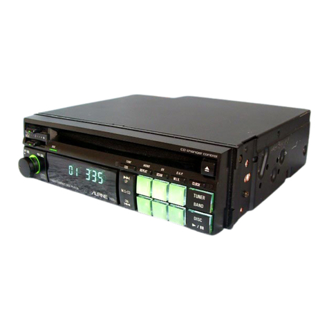
Alpine 7980M User manual

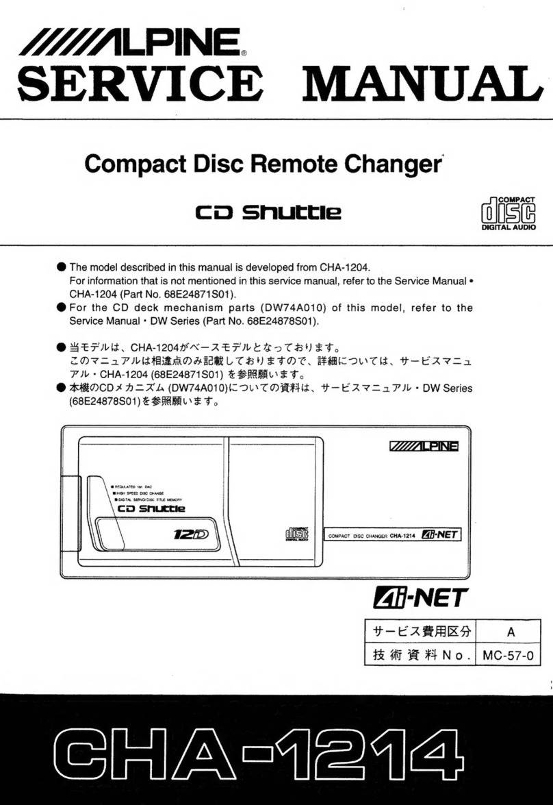
MUMALPINE
SERVICE
MANUAL
FM/MW/LW/SDK
In-Dash
CD
Changer
3D
Snuttle
|
olis(e
DIGITAL
AUDIO
@
This
model
is
component
system
unit
of
compact
disc
changer
and
tuner
unit.
@
For
the
CD
deck
mechanism
parts
(DS24A010)
of
this
model,
refer
to
the
Service
Manual
e
DS
Series
(68P50238W01).
MONO
TUNE
3230
sruactiea
COMPACT
DISC
CHANGER
|
CESCAN
T_oisF
>
a
ejo((=)
|||
MUNAPINE
8x
OS
20-BIT
ie
Geek
Pea
7980M
Contents
DPOCHI
CATIONS
oe
csipo
ce
Si
tees
since
saved
Seest
sass
seeshsebcetducnscbengsesutetecenarcpaascsuedigocecaasusde
ccasdeg
uu
sass
tedavacaeeecbaves
cl
vfecssecsneareabtenedes
me
teneceetecasteieientys
3104
EPROP
CANON
ses.
cc
chcoesaeacdace
seas
ai
daw
tenets
dulce
coayceiouigucdeu
ov
acan
even
dey
nen
anvats
noe
ooebeed
sehen
Date
ea
tod
eda
Meet
aevdiadk
cdo
aiizn
weeded
pedosveed
5
PRECAUTIONS:
cssesnecas
teaaststetascectetapec
tet
ateeceasesetees
dovtebecsesnagevecesusencesudosesgheewasdhaaatetacsanapdedbevusa
cous
sath
duossevaics
deveaves
deve
cteuusecasavevsdenurevonesenvsd
510
6
FOGUURGS
22
Focese
ba
ccscve,
eet
esecSeccau
ts
accbec
tea
cpanel
v
castes
caeaek
ex
vevious
shutens
save
dente
da
tencsteaeat
adecvel
one
iava
SN
eee
Met
data
lahe
Wola
daa
neat
6
Controls
and!
IMGICALOIS
messin.
sceceecbeesuipetins
beds
stvnsandunednansovasecccissnesiegnduncucdcdcouacaucenevssosbaconsonioca
siesuaccedecauesussusebibiiewe
eueuevens
cuverveneetacocss
cobesOn
ole
7to8
COMMOCHIONS
a5:
23.5.
A
scsaacecatecesecestascessestesceypuscessacelsbetgs
etunseyiss
eeedeupabags
raeususessesderagansutnca’doocsanacsetiestu
ste
sdedast
sles
sdéaths
dae
dheadieanaveneuciweientiees
7to9
OPEL
ALON
eseecctcenncesecciesccccavecstscn
cansslesds
ge
snesyeuwenvevcs
sieves
vuedaewievedeussn
ven
vesveueve
cous
saUeaveeseu
s5ua
bucod
aindseagodessegboye
casdedsancsesigead
sacs
sentuveseideeceenesiees
9
to
16
ACUSIMENtE
PrOCODUROS
ois
fs.
22h:<Gcaidecscasa
Sbcatceotecehis
abewsassdveccnesdededtagesGavgeduesnnunassasvsdee
asks
usaedeasaueosvouesdceseoiuoed
sbavdh
avecsesdoiacia
eeuesdeuazreevtnad
17
to
22
Adjustment
EOCations:siciisscces
eek
Seadees
cesses
cceshsctsaciaSitekedenaues
ccd
ccrvee
dicted
dee
ceacasseaeanse
ovesuestasuanal
ster
terueesedrdbaacasasaressveseetseenedictontieee
aie
23
to
24
Electrical
Inspection
Specifications...
ee
seeessssesecseeecsccsneesseeesnesenensscasseceescssccescesecsscessssensesessssesesecaesssausaescstsnssevessessseesecssseseseavacs
25
to
26
Packing
ASSOMbly
Parts:
LISt:,,
<esicsndsxesticccsncentiesvatvdete
sonavttonsevdpancuvaccydcentundis
cobavndes
sate
oatsasasds
auascaceveuitaysubevseeaausceansoueyssususasuneivucald
goavenobeveiices
27
Packing
Method:
View
3
c.c.istesvesccecsieeecceccdt
Seacestvecesbewaslaven
cic
cedecacdagdiede
dese
Aiascoaassubcbecacesbonad
testes
udantay
tusbbuiavicssaaeieeteadeveusestevsideensiatecouenweneeale
27
Changer
Unit
Disassembly
INStructions:s
-.scitscsdese.ceccccssvsaceciiecuscesoadslasesasieussesesoascucvelaceesbbassgeste
vousdedieucesedons'stdstelacde
$eivteusteorsuecodussdatenesusncati
esthue¥eaives
30
to
31
Description:
OF
IC
Terminals
ceaccssetcousicstcsoxovacsit
antearcvacsncd
tativataceiscst
unvvay
beatendeuvcaeaseseasveaisdvccsvatesbeateaediieazavs.dheteedssisnssedvergoanscnieeueanes
32
to
33
LGD:
DIS
DNA
5
22S
cicsaah
Svaceae
donot
adeuessdanabavstesdeandeyseetubeai
ye
jdsatinaataney-cenveydsensibiguesesnuaededena
diesen
evans
ye
deoucotedubsvatiaabecbagcd
svcd
socestaseasntenae
Seuaaeunuaeed
34
BIOCK*
Dig
rem
icdsicieeseseteesatcputeawitecascsteswicesesnentesuercouccox
ce
secevaeveasseps
cuss
ves:
kasyets
sel
cxibes
doc
ceegevelasdespuehaabacdsalegncevssteatsc
dovvdeebadiatatuaetocns
35
to
36
Parts
Layout
on
P.
C.
Boards
and
Wiring
Diagram
(1/2)
37
to
39
Parts
Layout
on
P.
C.
Boards
and
Wiring
Diagram
(2/2)
40
to
42
SCheMatic
Diagrarin-(1/2).!:escssvesvesesncesecevsvcsesssesececsecseewaoenseseatucszassccluigsvasnseused
sv’
aessuash
sasess
cach
toshaentwnesdeardetasnaondssuchesteisuatendatarme
ies
43
to
45
Schematic:
Diagram:
(2/2)
sis
coc
scocsuics
cateahchedas
svete
luted
cbiasay
atest
ceaze
Saursasuetts
Seva
Vist
dovadiasatava
cecavaanvesbedecsaeehuvacsceswade
said
eessehashackintanseiiae
caters
46
to
48
Electrical:
Parts:
LiSts
3
c..vssssscassietsencsuthsonpssessschendansoscaixaedvesesoieeetwutadesespatuacelsea
sactchbavteas
ctuctatestvndalelwavvesucterecbeshssvalivasdguvetaitdetevalde
davties
49
to
55
Cabinet
Assembly
Parts
List’.
2:52.50
25
Ses
pctcteeoess
neo
ctioene
dete
datas
desdakel
el
sdeaasevaa
A
fivies
eaiehadadesaastadaloveseveteadeleaiGessbohaascees
dail
ba
auaieutens
56
Exploded
View:
(Chamoer
Unit):
cicci
gos
cciyndet
St
ceed
che
eijenk
to
caten
ddan
evened
lies
idacelovtsdayii
sl
ealield
able
besinduncdsdesbeusbedladivasscvedoeiatuocevsngedseoiveus
sedans
57
to
58
Semi=
Conductor
Lead:
Identifications:
sviccsisscsassersiesseshertestersceteesseadserascosieaierssisdssivessuneevedscetaaeseudarsentstvsseveetssiasesesiveoeuieasesieedivade
weuess
59
to
65
Tuner
Unit
Description
ot:
IC
TErnimal)
ccscsases
cecccactaseecaneccadastevies
edevesbovesdosbenseutadseavinocabaisnsgeiesivedasvhiaschctuassaesesvitiiansaccantanivsceuteugsacodeucesnvearucdieueedt
68
to
70
FUME
SCHEMALUGC:
Diagram
isiscresiscbeesccsvecsdariecd
hcsecclucesss
Ueawsevshaadecevdevdestelvscveeutcnssdcseased
socdeczen
deivualsoasdas
cecchseucaucdueuvesuedueadevucdsusvedsad
cosvlenseuornsye
71
CabinebAssembly
Parts
List:
vsicd
cassie
cansscscescliecavsteateseaadohi
ovveGoscctdeadcaszasedcby'on
cos
edtush
teusdlusduat
dade
ivaduscdvcudbazaais
idsandetensasstsiatssdsseaiueioelsvees
siuneee
72
Exploded:
View:
(Tumer-UnIt)
sssusscjtisaaseeieas
iabssacstvaisecteesiacvscdasesnctcoanesesgestget
seudetsedeatationai
dedeseadaveus
oddagisanssavisanerssetesesebdatioy
atlciestetinoeaedes
73
to
74
BOCK:
DIAGT
ANN:
5.
cssese
eens
scsatine
seis
Seesca
cased
soanti
eat
debuoncapveuscass
haudcanQaa'e
ensue
duadueccbssuuedtidensab
tense
sususs
dee
Wevesiedaser
suis
ebssisataisaandider
sar
dertas
cavesrndboasied
75
to
76
Parts
Layout
on
P.
C.
Boards
and
Wiring
Diagram
77
to
80
Schematic
Diagram
(1.72)
-escvesscvestaedaseds
coasesd
sees
abe
oVaes
cute
sansatesncavela
Couto
ceasdckagouzeveca
ccawsacrvcsiaiedacovcesacsesudad
seecadasvalevadstacddasivine
eloiiobatolaeeaeee
81
to
83
SCHEeMatic:
Diagram.
(2/2)
vewiaices
scccece
cts
secsetowskctecbes
ov
tae
swe
tassve
vec
veasaede
ndash
gauedatsds
da
dassaadev
Sade
adiveeaucbdesbasvesosladzeaenssdecseiiians
sevedgeeoouaenees
84
to
86
Electrical:
Parts:
List:
ccccscscosecsaseeucosvsuvecacedd
cguseccavetsestaidineszcsenasessdicedie
ducal
dovbeaesaudatdaveleavawcdgivboudetecenss
seaecvuadtesssidicestetasevosh.
tion
havacner
87
to
92
Semi:=Conductor
Lead
Identifications
icctccciseviecscdacocesdessattvsiss3
tases
suedhentecbsacevetsteadhadoalGesueid
ens
adlvsouealigssaccusterdeeetovasediabsolotvneateuagaesiis
93
to
96
Spare
Schematic
Diagram
Inserted.
Specifications
<CD
SECTION>
7980M
SYStOM
ches
weray
le
ROR
RE
t
NOt thn ROS
ticle celta
28
ni
2
Ie
NBT
E
SN
Saale
covet
Nope
h
tet
1!
Optical
(Compact
Disc
system)
Quantizing:
BitiNUMBER”
co...
cows
As
oay
regs
¢
Ug
de
Tae
haw
Poa
ee
mamentad
>
Sea
age
Ng
gypteeneiee
rae
20
bit
Liner
system
Channelse.2,
avo
Gt
vee
aie
papas
bas
uae
paket
ds
alcheh
hee
DRE
Ye
whens
Bae
8
bei bas
Gbammtnng
eaateaan
oy
2Channels
Channel
Balance:
(1KHZ)
22.06
ocean
ohne
oe
eee
ankle
dee
eee
Pee
aah
bok
nee
eeae teak
niin
Sed
0+3dB
Distortion
GKHZ))
ccen
ews
aioe
saad
aida
GA
Pea
weave
ees bog
again
we
PASE
Res
he
o
as
shan
Paes
OS
bona
0.05%
Frequency
Response
(Ref.
1KHZ)
..
2...
e
een
ee
eee
cence
eect
eect
en
eeaee
17Hz:0+3dB
127Hz:0+2dB
10.007kHz
:
0
+
2dB
19.997kHz:
0+
4dB
SN,
Ratios
(RAZ).
vance
vetted
At
eld
Bled
reat
tal
Siete
5
vate
ote
ta
eed
alte
teen
SMa.
fiael
Sas
2
Ge
0
a
85dB
Separation
i(kHZ)
s...5e5
cosadee
chat
d
abt
ore
uae
dea ech
ie
gte
deheeats
alas
Ana
eis
Shae
aE
Nine
oho
ce
gh
NY
Res
alele
70dB
Noise
‘bevel
(at
Voliime:
Mui):
ied
Abc
eS
i
need
i
a
er
A
NE
nn
Nl
O.1mV
Currents
(atiPRAY):
24
cee Eee
de
Sheba
ode
dead
de
eae
nantes
sea
Meek
oe
eee
AG
Acct
tad
dit
gl
dal
ae
1.2A
De=Emphasis:
(Ref:
TkHZ).
ces
2senn
vai
en
Sea
eeveet
eons
doo
Sa
Meas
wee
cade
gee
ns
oRRS
DASA
4kHz
:-20+3dB
16kHz
:
-20
+
3dB
<FM
SECTION>
Intermediate
Frequency,
uc
oa
ee
ech
ALS
PE
Se
Bee
hs
k
Pie
as
anes
dk
LR
Re
bh
naabaie
ties
10.7
£0.1MHz
FFEQUENCY”
RANGE
+
-o.sc
dis
cedure
ep
am
caters
cei
acine-dra-ere
med
pereards
s
Heed
Gis
EY
Gg
oars
Haroon
de
ere
pte
Meee
87.5~108MHz
Usable
Sensitivity
(Mono,
98.1MHz,
30dB
S/N)
......
aPisdletgctine
ste
s
Ses
en
da
As
sald
aaihaa
An
ann
gronaeeet
tatetase
17.20dBf
-10dB
Limiting
Sensitivity
(Mono,
98.1MHZ)
2.2.0.0...
ccc
cc
e
ene
b
teen
e
ete
e
een
eee
17.2
+
5dBf
S/N.
Ratio
(Stereo
98s.MHZ).
sivas
onesie.
te
Seieeda
Set
5
8
os
ees
Sebi
Scala’. slaabeh
gaat
ad
ao
aedaaad
eee
ee
edd
48dB
Image:
Rejection=(106:1MAZ)
si.cece-sccnencase
wees
cues
Guile
anand
Sasi
6-9
MARR
AEC
AES
Sigh quod
ig
viaaianad’e
alets
dd
ala
ee
oh
we
40dB
IE
Rejection:
(90SIMHZ)!
Scag
sg.
ctr
tne
tel
Salegiess
taaselsintas
go
uae
bg
wlbie
us
wl
Sisie
ae
PRICE
aoe
Renee
wo
CLEA
ENE
od
60dB
Distortion
(Input.
TMV;
9B1MHZ).
oc.
occ
ean
cb
pee
et
bee
te
REE
eine
deeb
ye
ENS
beta
GuGediGa
dea
db
ade
bed
Aedan
1%
Frequency
Response
(98.1MHz,
Ref.
400HZ)
.......0
2.00.
e
ccc
ne
ec
cece
teens
100Hz:0+3dB
10kHz
:
-12
+
3dB
Stereo:
Separation
KHZ)is
320
flee
sna
leeodidedne
cased
oan
yeas
eet
oead
kad
opalsene
dale
uate
ten
dltled
Abele
hd
25dB
<MW
SECTION>
Intermediate
Frequency
xii.
ore
oi
rete
cea
og
bind
Garhi
nenatianctoeieng
os
24
Serge
que
aremtsis
eat
peared
450kHz
FreQUeHiGy
RANGE)
a
tunics
pase
oe
ete
le
alte
gale
a
teurglh
sercoelnans
Patent
de
cdg
oy ma
een
eR
SN
eE
SS
tS
531~1,602kHz
Sensitivity:
QOAB
S/N;
GOQKHZ)
os
oes
cnie
see
ceace:
revere
once
wsarelotbndety
Styne
BA
Sale
a
csersidle
aeliallay
es
eveqege
doacesagevie
sland
eataniea
dais
eb Os
34dB
GST
Nhat
OGG
Aas
ccancAcdangedeRides
tlt
Maactn
dss
ol
Oy
rcanauuuatadiinth
nen
otal
aN
i8
ot
lotto,
44d
Image.-Rejection®(1404kH2)"
23
css
Se
ie
aed
Seward
ote
eatee
os
onew
opie
satan
le
yee
Sauda
odd
dd
leidcadddei
tase
ws
50dB
IE
Rejection.
(GO3KHZ):
ccc
cee
nk
meee
ey
be
wey
eelabiis
edad
akarne
saa
Nevels
Diode
bee
ade
ee
eed
ae
x
60d8
Distortion:
:(999KHZ)'
2
cael
Sachets
Pek
ee
te
Sag
bee
Scat
ale
dg
ico
wh
See
AG
Da
RGS
be
bel
ake
Bhan
doce
2%
SK
Sensitivity
(at
98-MHZ)
cc
ccccc
ccd
ene
ce
econ
Keele
da
eee
ae
Oo
bind
EEE
Ree
we
lmelnae
elena
gnsia
ek
ward
e
nib
le
eueee
Sie
144B
Frequency
Response(999kHz,
Ref.
400HZ)
...
0...
cence
ented
teenie
eenes
100Hz
:-3+4dB
4kHz:-12
+648
<LW
SECTION>
Intermediate
Frequency
...........
0...
eee
cece
eee
eee
cabs
Seals
Blaierwcstnyernnch
aves
amerete
en
iin
al
aa
leacetenaceen
At,
450kHz
FICQUENCY
(RANGG
oii.
One
coer
Res
band
Ae
We
Babb
tueaes
ape
we
eal
ek
haan
aes
cup
kaw
seta
aay
Rand
153~281kH4z
Sensitivity,
C20dB.
SiN;
27
6KHZ):
ck
ont
Aoore
me
aM
ease
oat
the
aleteanesGnlyn
er ae
kien
Geb
M
REED
Dah
od
oe
ladies
414
B
SN
RATIOAQIOKAZ)
coda.
sets
th
hea
ee
ag
Med
eae
eee
Rede
asin
tenes
dae
wetland
ag
Deere
dopa
ees
40d
B
Image:
Reje
cions(Z16KAZ)-s
sss
veneak
Aa
settee
a
aa
iv
Aen
a
oe
tke
ie
cnt
iltee
ell
ey
wate
ee
ch
edness
whakders
50d
B
IF.
RejectiOn(216KH2Z):
2c
ge
cei
oed
Wisco
ated
Rana
ois
gh
Seep
Lata,
Oka
CMa
eG
add
Aaah
aaNet
ADEA
A
aehe
sadness
50¢
B
7980M
DISCORION
yaks
nciar
se
cot
een
hee
cas
ae
neta,
eee
BE
BE
Teale
akon
uh
tee
a
ahh
sees
Sect
ne
atatane
eM
ahh
et
eA
ania
SR
RES
Lte
et
Pi
2%
Frequency
Response
(216kHz,
Ref
400kHz)
........
22.0202
100Hz:
-3+4dB
4kHz
:-12+6dB
<
GENERAL>
PoWer
Supply”
“s.ce.8enc
toa
cos
teeta
een
eee
ite
ake
RASS
haeleemen
oR
abin
Mare
eh
a
ee
DC
14V
Pre-Output
Impedance:
fac
2
reeds
said
eh
eee
hee
ee
OSES
CRRA
oe
glans
ailiteaes
ciara
ean
Mee
Seg
oe
1.6V/10kohm
S@MICONGUCCONS
cao
cod
ehaad
de
eaece
doen
pe
eee
eee
Oe
Changer
Unit:
261C’s,
39
Transistors,
15
Diodes,
11
Zener
Diodes
Tuner
Unit:
191C's,
50
Transistors,
24
Diodes,
6
Zener
Diodes
(C)
19
IC's,
53
Transistors,
24
Diodes,
6
Zener
Diodes
(@)
DIMeNnsions
(WXH
XD):
nhersccccane
taatenseesleal
se
thaaa
a
hies
ie
pees
take
Changer
Unit:
178x50x
153mm
Tuner
Unit:
178x25
x
150mm
Weight:
cvisaiclnnoke
do.
dbs
chi
cae
oem
een
eine
tote
g
eae
eons
iain
aus
ceets
Nels
amnmenintis
name
ok
Changer
Unit:
2.2Kg
Tuner
Unit:
0.7Kg
Notes:
Due
to
continuing
product
improvement,
specifications
and
designs
are
subject
to
change
without
notice.
©:
For
except
Germany
Model
only.
@
:
For
Germany
Model
only.
Others
:
Common.
ERROR
INDICATION
ce
Magazine
cannot
be
ejected.
Press
the
eject
button
and
set
to
Disc
is
not
drawn
out
or
set
the
play
mode.
If
the
play
mode
back
into
the
magazine
tray.
can
not
be
set,
press
the
eject
Disc
change
operation
does
not}
button
again.
Once
the
magazine
function.
is
ejected,
reinsert
it
then
set
the
play
mode.
If
the
magazine
can
not
be
ejected,
contact
a
service
shop.
Press
the
eject
button
to
eject
the
magazine.
Now
insert
an
empty
magazine
and
recover
the
disc.
If
this
does
not
work,
contact
a
service
shop.
Disc
is
drawn
out
of
the
magazine
tray
but
is
not
set
back
into
it.
Press
the
eject
button
to
eject
the
magazine.
If
there
is
a
disc
inside
the
changer,
insert
an
empty
magazine
and
recover
it.
If
this
does
not
work,
contact
a
service
shop.
Magazine
does
not
move
forward
or
backward.
Wait
for
several
seconds.
If
no
signals
are
transferred,
turn
the
ACC
power
off
then
back
on.
If
the
problem
persists,
disconnect
the
battery
power
lead
and
ACC
power
lead,
then
reconnect
them.
If
the
problem
still
persists,
check
the
connection
of
the
DIN
cable.
If
the
problem
still
can
not
be
solved,
contact
a
service
shop.
No
transfer
of
signals
between
changer
and
audio
box.
The
error
display
turns
off
once
the
temperature
returns
to
normal.
Excessively
high
temperature
detected
in
car.
PRECAUTIONS
Do
not
attempt
to
repair
or
service
the
unit
yourself;
return
the
unit
to
your
nearest
authorized
Alpine
Service
Station
for
servicing.
Cautions
before
installation
The
magazine
is
pushed
out
forward
(approximately
8cm
from
the
panel)
when
discs
are
changed
or
magazine
is
ejected.
To
take
out
the
magazine,
a
free
space
of
more
than
14
cm
is
required
from
the
front
panel.
Select
a
place
for
installation
where
the
magazine
is
ejected.
Select
a
place
for
installation
where
the
magazine
will
not
hamper
stick
shift
operation.
More
than
14
cm
Temperature
in
the
vehicle
When
your
car
is
parked
for
a
long
period
of
time
during
the
summer
or
winter,
the
temperature
inside
the
car
fluctuates
greatly.
The
temperature
inside
the
vehicle
should
be
between
+60°C
and
—10°C
(+140°F
and
+14°F)
when
operating
the
unit.
Cautions
during
Playback
Playing
a
disc
while
driving
on
a
very
bumpy
road
may
result
in
skips
but
this
will
not
scratch
the
disc
or
damage
the
player.
The
noise
level
on
compact
discs
is
much
lower
than
on
analog-type
records
or
tapes.
Therefore,
before
playing
a
disc,
turn
the
volume
control
fully
counterclockwise,
then
adjust
volume
by
gradually
turning
the
control
clockwise
once
playback
begins.
Do
not
turn
clockwise
too
abruptly
as
this
could
damage
the
speakers.
Handling
Magazine
The
magazine
is
automatically
pushed
out
forward
when
a
disc
is
changed.
When
this
is
done,
do
not
press
on
the
magazine
strongly
with
your
hand
or
subject
it
to
strong
shocks,
as
this
will
result
in
damage.
Also,
operate
in
such
a
way
as
to
not
hamper
driving,
as
you
may
knock
on
the
magazine
when
shifting
gears.
Improper
Improper
CAUTION:
@
Do
not
insert
anything
other
than
magazine
into
insertion
slot.
@
Do
not
remove
the
unit
from
the
Q.R.B.
before
ejecting
the
magazine.
If
the
unit
with
the
magazine
installed
is
dropped
onto
a
floor,
the
disc
will
be
damaged.
FEATURES
MAGAZINE
HOUSING
3
CDs
Three
5-inch
(12
cm)
compact
discs
can
be
housed
in
the
CD
magazine.
Any
one
of
the
3
CDs
in
the
magazine
can
be
quickly
and
easily
accessed
for
playback
of
the
entire
disc
or
individual
selections.
FULL
FRONT
DIN™
CHASSIS
Q.R.B.
(QUICK
RELEASE
BRACKET)
WIRELESS
REMOTE
CONTROL
The
7980M
comes
equipped
with
a
wireless
remote
control
that
can
control
the
tuner
and
CD
changer
functions.
8
TIMES
OVERSAMPLING
DIGITAL
FILTER
HYBRID
IDAC
Alpine’s
20-bit
Hybrid
interpolative
DAC
combines
1-bit
D/A
conversion
technology
(for
excellent
low
level
linearity)
and
a
multi-bit
D/A
converter
(for
best
Dynamic
Range,
Signal-to-Noise
Ratio,
and
jowest
distortion
and
noise
characteristics).
The
result
is
flawless,
accurate
performance,
outstanding
resolution
and
detail
along
with
superb
Dynamic
Range.
M.I.X.
The
tracks
on
disc
will
be
played
randomly.
REPEAT
When.the
repeat
button
is
pressed,
the
current
track
will
be
played
back
repeatedly.
DISC
SCAN
Plays
the
beginning
of
each
track
for
ten
seconds
before
skipping
to
the
next
track.
Upon
locating
the
desired
location,
press
the
DISC
SCAN
button
again
to
stop
the
scanning
and
play
through
the
selection.
INTELLIGENT
AUTO
MEMORY
In
the
Auto
Memory
mode,
the
6
strongest
stations
in
each
band
will
be
stored
automatically
in
the
memory
presets.
INTELLIGENT
PRESET
SCAN
The
stations
currently
stored
in
memory
preset
locations
are
scanned
automatically
for
ten
seconds
each.
The
Intelligent
Preset
Scan
will
only
scan
the
strong
stations.
Weak
stations
will
be
skipped.
D.A.P.
(DIRECT
ACCESS
PRESETS)
D.A.P.
allows
storing
FM,
MW
and
LW
stations
on
the
same
band,
eliminating
the
need
to
press
the
band
select
button.
Up
to
6
stations
can
be
stored
in
the
0.
A.P.
band.
LITETOUCH™
30-STATION
PRESETS
FM1:
6,
FM2:
6,
MW:
6,
LW:
6,
D.A.P.:
6
S.T.M.
(SOURCE
TONE
MEMORY)
Automatically
memorizes
the
settings
of
your
Bass/Treble
Controls
for
each
source.
DUAL
PRE-AMP
OUTPUTS
Dual
pre-amp
outputs,
along
with
a
pre-amp
fader,
make
easy
and
completesystem
expansion
possible.
7980M
7980M
CONNECTIONS
CONTROLS
AND
INDICATORS
(ies
Listed
below
are
all
the
Controls
and
their
Indicators.
Please
see
the
Operation
Section
for
explanations.
@®
Disc
SELect
Button
/DX
(Local/Distance)
Button
SDK
Switch
Eject
Button
Magazine
Loading
Slot
TUNER/BAND
Button
DISC
(Play
p»
/Pause
II
)
Button
SCAN
Button
REPEAT
Button
M.LX.
Button
S©GQL0Q®
©8686
Station
Preset
Buttons
Band
Indicators
Preset
Address
indicators
Digital
Display
SDK
Indicator
STereo
Indicator
MOno
fndicator
ALL
Re
peat
Indicator
RePeaft
indicator
DX
Indicator
@EE99
OS099
D.A.P.
(Direct
Access
Preset)
Button
S8S888 888898
®
M.I.X.
Indicator
A.
MEmo
Indicator
SEEK
Indicator
D.A.P.
Indicator
UP
(>>|)
Switch
DN
(H<)
Switch
POWER
On/Off
Switch
Sensor
Window
for
Remote
Control
TUNE/DISP
Switch
Audio
MODE
Select
Switch
/Audio
Level
Control!
MONO/Preset
SCAN
Button
Speaers
Lautsprecrer
Haut-paneurs
Aitopaniand:
Attavoces
Hoguiare
Frontief
Vorne
hnker
Devant gaucne
Anteriore
snstto
Detantero
cquerdo:
Vanster
hoguatare
fram
Front
ngnt
Vorne
rechter
Devant
dro
Anteriore
desto
Delantero
derecno
Hager
nogratare
tram
Rear
eh
Postenore
srusto
Traseo
izqwerdo
vanster
hog.a.are
bas
Rear
agnt
minten
recnie-
Amere
dron
Postenore
desvo
Trasero
dereno.
Oger
nograiare
bak
[I
REMO=E
ON
|
Bive
ete
Bla,
We-3}
Brown
Wnite
i
Bran
Wed)
Yeionw
Ger
Rec
Ro:
7380M
Tuner
Unit
7980M-Radioteil
Syntonisateur
7980M
Sintonizzatore
7980M
Sintonizador
7980M.
7980M-Tuner
‘Pink
/werites
Rosa!
Wels,
(Biue/worte;
{Blau/Weik)
(Yettow)
{Gelb)
iWeite/Blve)
Wes
Biaui
OIMMER
CONTROL
Abblendrege!
7980M
Changer
Unit
7980M-Wechsierted
Changeur
de
CD
7960M
Caricatore
CD
7980M
Cambiador
CD
7980M
7TS80M
CO-vaxare
Al
fro
gi
ingresso
dell
mre
Aun
cable
de
enteaga
de
rater
uotor
de
Till
ingangskabein
tor
ludavbrutt
9a
en
annan
apbarat
Ty
puwer
anienna/Zu
Power
Ant
Vers
l'antenne
de
purssance/All
antenna
di
potenra
Ale
antena
electrica/Tull
ef
antenn
To
venicie
phone/Zu
dem
Teleonon
des
Fatrreuges,
Vers
le
telepnune
du
venicule
At
telefono
del
veccoto/Al
teletone
de!
veniculo
Till
Dittetefon
To
ampbtrer
or
equalizer
Zu
Verstarner
coer
Equatver
Ignnon
Key
amplifcatore
o
all
equaluzatore
Zufaechtussel
At
ampliticador
0
ai
ecualzador
Cline
contact
Tall
torstarkare
eller
equahzer
Chave
di
accensione
Liave
de
encendido
Tantnycket
Battery
Batterve
Bitterie:
Bitteria
Bueria
Buters
To
aummer
contol
lead
Zur
Helligneits
Steuerieitung
meee
VES
Je
conducteur
de
commande
du
gradateur
Al
féo
di
controtio
det
dimmer
Al
cable
de
control
del
reductor
de
luz
Tw
waple
for
dampning
av
belysningen
i)
CS)
6
Audio
Interrupt
Out
Lead
(Pink/White)
Power
Antenna
Lead
(Blue}
When
loaded
with
a
power
antenna,
connect
to
the
+B
terminal
of
the
power
antenna.
Audio
Interrupt
In
Lead
(Pink/White)
Remote
Turn-On
Lead
(Blue/White)
Connectthis
lead
to
the
remote
turn-on
lead
of
your
amplifier
or
signal
processor.
Switched
Power
Lead
(Ignition)
(Red)
Connect
this
lead
to
an
open
terminal
on
the
vehicle’s
fuse
box
or
another
unused
power
source
which
provides
(+)12V
only
when
the
ignition
is
turned
on
or
in
the
accessory
position.
Battery
Lead
(Yellow)
Connectthis
lead
to
the
positive
(+)
post
of
the
vehicle’s
battery.
Ground
Lead
Connect
this
lead
to
a
good
chassis
ground
on
the
vehicle.
Make
sure
the
connection
is
made
to
bare
metal
and
is
securely
fastened
using
the
sheet
metal
screw
provided.
Dimmer
Control
Lead
(White/Blue)
Connectthis
lead
to
the
lead
in
the
vehicle’s
parking
lights
circuit
that
provides
(+)12V
when
the
parking
lights
are
turned
on.
This
will
dim
the
unit's
backlighting
at
night
when
the
parking
lights
are
on.
Power
Wiring
Harness
(Included)
Connect
to
the
Power
Supply
Connector
40.
Power
Supply
Connector
Connect
to
the
receptacle
of
Power
Wiring
Harness
@.
Fuse
Holder
(3A)
DIN
Extension
Cable
(Included)
DIN
Connector
Connect
this
to
the
DIN
connector
on
the
Tuner
Unit.
RCA
Extension
Cable
(Sold
Separately)
DIN
Jack
Rear
RCA
Jacks
RED
is
right
and
WHITE
is
left.
Front
RCA
Jacks
RED
is
right
and
WHITE
is
left.
Antenna
Receptacle
OPERATION
«
BASIC
OPERATION
>
Preparation
for
Playback
1.
Insert
your
discs
(up
to
3)
into
the
disc
slots
of
the
CD
magazine
with
the
label
side
facing
up
(Fig.
C).
To
remove
discs
already
in
the
CD
magazine,
push
the
lever
on
the
CD
magazine
for
the
disc
you
wish
to
eject.
The
disc
will
come
halfway
out
from
the
CD
magazine,
so
pull
out
the
disc
by
grasping
the
disc
by
the
edge
with
your
hand
(Fig.
D).
NOTE:
Hold
the
disc
so
you
will
not
leave
fingerprints
on
the
disc
surface
(refer
to
“PROPER
CARE
OF
YOUR
DISC"
section).
2.
Insert
the
CD
magazine
ail
the
way
into
the
7980M
with
the
narrow
side
facing
the
unit
as
shown
here
(Fig.
&).
Magazine
Fig.
E
NOTES:
1.
Do
not
insert
heat-deformed
discs
into
the
CD
magazine.
2.
Do
not
forcibly
remove
the
CD
magazine
by
hand.
3.
Only
one
disc
can
be
inserted
in
each
housing
slot.
Attempting
to
insert
another
disc
may
cause
damage.
4.
Only
compact
discs
containing
the
mark
shown
below
can
be
used.
Ist,
DIGITAL
AUDIO
5.
To
play
3-inch
discs,
you
must
use
the
(4908)
adapter
ring.
6.
When
using
the
3-inch
discs,
insert
only
one
disc,
not
more
than
one.
OPERATION
Turn
the
Audio
MODE
Select
switch.
Right
Volume
Maximum
Indication
example
VOL
adjust.
(G
—
35)
Volume
Minimum
2
&
c
3$
TRE
adjust.
(-7
—
+7)
Treble
Minimum
Treble
Maximum
Bass
Minimum
Bass
Maximum
BAS
adjust.
(—7
—
+7)
£S
-3
39-4
BS
BAL
adjust.
(—
—
8)
Output
at
Left
Output
at
Right
Channels
only
Channels
only
alae
Bes
FAD
adjust.
(—
—
8}
Output
at
Rear
Output
at
Front
Channels
only
Channels
only
Peale
Fe
8
FF
g
How
to
adjust
the
volume
and
tone
(Refer
to
the
diagram
above.)
1.
Turn
on
the
system
by
pushing
the
POWER
On/Off
switch
@
or
any
other
button
(other
than
Eject
button
@).
2.
Press
the
Audio
MODE
Select
switch
@
to
select
each
adjusting
mode.
VOL
—>
TRE
—>
BAS
—>
BAL
—>
FAD
—>
VOL
Each
time
this
switch
is
pressed,
the
mode
changes.
The
mode
is
indicated
in
the
display.
The
mode
indicator
changes
as
each
mode
is
selected.
3.
Once
the
desired
mode
appears
in
the
display,
rotate
the
Audio
MODE
Select
switch
80
to
make
your
adjustment.
The
display
will
return
to
the
previous
mode
indication
after
five
seconds.
Power
Off
Press
the
POWER
switch
@
to
turn
the
unit
off.
~10—
OPERATION
$.T.M.
(Source
Tone
Memory)
The
Bass
and
Treble
controls
can
be
individually
set
for
each
source
(FM,
MW/LW,
and
CD).
Once
set,
their
positions
are
automatically
memorized.
Whenever
the
source
is
reselected,
the
Bass
and
Treble
controls
will
return
to
your
preset
configuration.
Function
Switching
1.
Tuner
Mode
Press
the
TUNER/BAND
button
©
to
switch
from
CD
to
Radio.
2.
CD
Mode
Press
the
DISC
(
»/II
)
button
@
to
switch
from
Radio
to
CD.
«RADIO
OPERATION
>
If
the
unit
is
not
in
the
Radio
mode,
press
the
TUNER/BAND
button
©.
Tuning
Band
Selection
Press
the
TUNER/BAND
button
©
to
select
the
desired
tuning
band.
The
Band
indicator
42
shows
your
selection.
Switching
the
FM
Volume
Use
this
function
if
the
difference
in
volume
is
great
when
switching
between
a
CD
and
the
FM
radio.
1.
Press
the
TUNE
switch
@
for
2
seconds.
2.
Press
the
Preset
No.
1
button
@
to
switch
the
display
between
“F-HI”
and
“F-LO”.
The
FM
volume
can
be
set
to
one
of
two
positions,
high
or
low.
Set
the
position
according
to
the
broadcast
station.
F
-
HI
F-LO
Local/Distance
(DX)
Sensitivity
Switching
for
FM,
MW
and
LW
You
can
select
the
radio
SEEK
sensitivity
(local
or
distance
(DX))
by
pressing
the
DX
button
@
for
more
than
two
seconds.
In
the
distance
mode,
with
DX
indication
@,
the
radio
tunes
in
both
strong
and
weak
stations
(all
stations
from
A
to
M
in
the
illustration).
In
the
local
mode,
with
no
DX
indication
@,
the
radio
tunes
in
only
strong
stations
(stations
C,
F,
H
and
L
in
the
illustration
below).
°°
=
H
aD
CA”
(senses
sellSeete
ces
cS
eS
te
o
8
€
7
eo
Jul
l
ft
Ta
i
<4
n
Station
Frequencies
44m
|
7980M
7980M
OPERATION
FM
Stereo/Monaural
Switching
You
can
select
between
the
Auto
Switching
or
Monaural
only
for
FM
reception
by
pressing
the
MONO
button
@).
In
the
Auto
Switching
mode,
you
can
receive
stereo
broadcasts
in
stereo
and
monaural
broadcasts
in
MONO.
The
STereo
48
or
MOno
indicator
(
shows
you
which
one
is
being
received.
In
the
monaural
mode,
you
will
receive
the
broadcast
in
monaural
only,
even
if
the
broadcast
is
in
stereo.
The
monaural
only
mode
quiets
the
noisy
stereo
signal
of
weaker
broadcasts.
The
STereo
indicator
will
not
appear
while
the
Monaural
mode
is
selected.
Manual
Tuning
1.
Press
the
TUNE
switch
@
until
the
SEEK
@
and
A.
MEmo
@
indicators
disappear
in
the
display.
2.
To
select
the
tuning
band,
press
the
TUNER/BAND
button
®.
The
Band
indicator
@
shows
your
selection.
3.
To
tune
to
higher
frequencies,
press
the
UP
switch
@.
To
tune
to
lower
frequencies,
press
the
DN
switch
@.
Auto
SEEK
Tuning
1.
Press
the
TUNE
switch
@
until
the
SEEK
indicator
@
appears
in
the
display.
2.
Select
the
tuning
band
with
the
TUNER/BAND
button
©.
3.
Press
the
UP
@
or
DN
@
switch.
The
unit
automatically
tunes
to
the
next
higher
or
lower
frequency
and
locks
on
that
station.
Manual
Memory
Programming
Follow
the
instructions
below
to
enter
stations
into
preset
memory:
1.
Select
the
tuning
band
(FM1,
FM2,
MW,
LW)
with
the
TUNER/BAND
button
©.
2.
Tune
in
your
desired
station
using
manual
or
auto
seek
tuning.
3.
Press
the
Preset
button
number
1
@
for
more
than
two
seconds.
The
preset
indicator
@
in
the
display
will
begin
to
blink.
The
tuning
band
(FM1,
FM2)
can
be
changed
by
pressing
the
TUNER/BAND
button
©
if
you
wish
to
change
bands.
Press
that
Preset
button
again
while
the
display
is
blinking
(within
5
seconds).
4.
The
frequency
you
selected
will
be
placed
into
Preset
Memory
number
1
and
will
appear
in
the
display.
NOTE:
If
a
preset
memory
has
already
been
set
in
the
same
address,
it
will
be
cleared
and
the
new
station
will
be
memorized.
5.
Follow
steps
2
—
4
for
the
remaining
presets
(2
—
6).
This
procedure
should
be
followed
for
FM1,
FM2,
MW
and
LW.
NOTE:
While
setung
the
memory
presets
you
can
switch
back
and
forth
between
FM1
and
FM2.
However,
while
in
this
mode
you cannot
switch
back
and
forth
from
MW/LW
to
FM.
OPERATION
Auto
Memory
Preset
1.
Press
the
TUNE
switch
@
to
light
up
the
A.
MEmo
indicator
@.
2.
Select
the
desired
tuning
band
(FM1,
FM2,
MW
or
LW)
with
the
TUNER/BAND
button
©.
NOTE:
The
Auto
Memory
Preset
procedure
is
allowed
in
the
D.A.P.
Mode.
3.
Press
the
UP
@
or
DN
@
switch.
The
tuner
will
automatically
seek
the
six
strongest
Stations
in
the
selected
band
and
memorize
them
in
order
of
their
signal
strength.
These
stations
are
automatically
placed
in
the
preset
memory
with
the
strongest
station
in
Preset
No.
1
and
the
6th
strongest
station
in
Preset
No.
6.
When
seeking
stations,
the
tuner
first
seeks
in
the
local
tuning
mode.
If
less
than
6
stations
are
memorized,
the
tuner
seeks
again
in
the
distance
(DX)
mode.
4.
After
finishing
the
Auto
Memory
Preset,
the
tuner
goes
to
the
station
placed
in
Preset
Memory
No.
1.
tf
no
stations
are
memorized,
it
returns
to
the
original
station
you
were
listening
to
before
the
Auto
Memory
Preset
procedure
began.
Preset
Tuning
After
the
preset
stations
have
been
memorized,
you
can
tune
in
your
desired
station
(within
the
band
displayed)
with
one
touch
of
a
button.
1.
Select
the
tuning
band
(FM1,
FM2,
MW
or
LW)
with
the
TUNER/BAND
button
©.
2.
Press
any
one
of
the
Preset
buttons
@
and
the
number
of
that
preset
will
illuminate
in
the
matrix
display
3.
The
frequency
of
the
station
placed
in
the
selected
preset
location
will
appear
in
the
display.
D.A.P.
(Direct
Access
Presets)
This
feature
allows
the
storage
of
FM,
MW
and
LW
presets
on
the
same
band.
Press
the
D.A.P.
button
@)
to
light
up
the
D.A.P.
indicator
@.
To
program
stations
into
the
D.A-P.
band,
follow
steps
1
—
4
as
described
in
the
Manual
Memory
Programming
section
on
page
14.
Accessing
the
D.A.P.
Presets
1.
Press
the
D.A.P.
button
@.
The
D.A.P.
indicator
@
will
illuminate
in
the
display.
2.
Press
one
of
the
Preset
buttons
@.
3.
The
frequency
of
the
station
placed
in
the
selected
D.A-P.
location
will
appear
in
the
display.
Preset
Scan
This
feature
locates
the
six
stations
preset
in
memory
on
each
band
and
plays
10
seconds
of
each,
in
numerical
order
from
Preset
No.
1
to
No.
6.
1.
Select
your
desired
tuning
band
by
pressing
the
TUNER/BAND
button
©.
2.
Press
the
P.
SCAN
button
@)
for
more
than
two
seconds.
3.
The
digital
display
will
indicate
the
frequency
of
the
preset
station
tuned
inamd
the
corresponding
preset
indicator
in
the
display
(for
each
preset
1
through
6)
wilf
blink.
For
FM
presets
it
will
scan
FM1,
then
FM2
and
continue
to
cycle
betweenthese
two
bands.
4.
When
your
desired
preset
station
is
reached,
press
the
P.
SCAN
button
@for
a
second
time.
The
indicator
on
the
Preset
button
will
stop
blinking
and
the
unr
will
remain
on
the
selected
station.
Sie
OPERATION
@
Traffic
Information
Receiving
This
model
is
equipped
with
traffic
information
receiving
apparatus
to
be
used
in
West
Germany
where
the
traffic
information
is
broadcast
in
FM.
The
following
is
how
to
use
this
unit
to
receive
traffic
information
broadcasting.
Four
preset
volume
levels
can
be
set
for
traffic
information
reception
in
the
SDK
mode.
Set
the
ALARM
LEVEL
selector
switch
on
the
Tuner
Unit
to
the
desired
level.
itt
High
~—>~
Low
NOTE:
When
setting
the
ALARM
LEVEL,
be
sure
to
turn
the
ACC
power
supply
OFF.
Two
ways
are
selectable
when
traffic
information
reception
signal
is
weak
in
the
SDK
mode.
1.
Press
the
TUNE
switch
@
for
2
seconds.
2.
Press
the
Preset
No.
3
button
@)
to
switch
the
display
between
“ALA”
and
“SRCH".
When
the
ALA
is
selected,
alarm
goes
off
and
when
the
SRCH
is
selected,
other
broadcast
station
is
sought
automatically.
e
Radio
Mode
1.
Select
FM
position.
2.
Depress
the
SDK
switch
@
and
tune
to
a
station.
If
the
station
is
a
traffic
information
station,
the
SDK
indicator
@
will
glow
and
show
the
reception
of
a
broadcast
from
a
traffic
information
station.
NOTE:
SDK
Indicator
When
SK
signal
is
received
irrespective
of
the
SDK
switch
position,
the
SDK
indicator
will
illuminate.
3.
In
the
SDK
moge,
stations
other
than
traffic
information
stations
are
muted
and
cut
out.
Therefore,
it
is
easy
to
select
a
traffic
information
station.
4.
As
the
signal
of
the
tuned
traffic
information
station
becomes
weak,
the
SDK
indicator
will
extinguish.
Then
after
the
lapse
of
25
seconds,
a
rhythmical
alarm
will
sound
to
urge
retuning
tc
ancther
stronger
station.
If
the
reception
of
further
traffic
information
is
required,
tune
in
the
desired
traffic
information
station.
When
received,
the
alarm
will
stop
and
the
SDK
indicator
illuminates.
Since
the
alarm
will
continue
if
no
signals
from
any
other
traffic
stations
can
be
received,
release
the
SDK
switch
for
reception
of
normal
broadcasting.
=43'=
OPERATION
5.
Even
if
the
Volume
control
@0
is
set
to
the
minimum
position,
the
volume
of
the
traffic
information
will
be
automatically
adjusted
to
the
level
preset
by
the
special
volume
control
on
the
Tuner
Unit.
After
the
message,
the
sound
volume
returns
to
the
previously
adjusted
level.
6.
If
traffic
information
reception
is
no
longer
necessary,
release
the
SDK
switch
for
normal
radio
reception.
NOTES:
e
When
the
SDK
switch
is
pressed
and
there
is
no
SK
signal,
ALARM
will
sound
after
the
lapse
of
25
seconds.
Press
the
SDK
switch
again
to
stop
it.
e
When
the
SEEK
operation
is
carried
out
with
the
SDK
switch
turned
on,
the
SEEK
operation
stops
at
a
traffic
station
only.
e
The
A.
MEMO
operation
with
the
SDK
switch
turned
on:
only
the
traffic
stations
will
be
memorized.
e
This
system
has
a
special
volume
control
on
the
Tuner
Unit
for
adjusting
the
volume
level
for
SDK
reception
and
the
alarm
which
will
sound
when
there
is
no
SK
signal
in
the
SDK
mode.
Set
the
Volume
control
@
to
the
minimum
level
position,
and
adjust
the
special
volume
control
on
the
Tuner
Unit
to
your
desired
level
with
a
screwdriver.
e
CD
Mode
1.
When
the
unit
is
playing
a
CD
with
the
SDK
switch
pushed
in
and
tuned
to
a
traffic
information
station,
the
CD
play
is
interrupted
and
changed
to
FM
radio
if
the
pre-tuned
station
begins
a
traffic
information
message.
When
the
message
is
over,
the
unit
reverts
to
CD
play
automatically.
2.
Only
when
the
SDK
switch
is
on,
the
SDK
display
will
appear
if
a
traffic
information
Station
is
being
tuned.
3.
When
your
receiver
cannot
receive
a
traffic
information
station
after
a
reception
of
the
traffic
information
station
with
the
SDK
switch
on,
the
receiver
automatically
starts
a
SEEK
operation
after
25
seconds,
and
receives
another
station.
4.
When
the
TUNE
switch
@
is
pushed
with
the
SDK
switch
turned
on,
the
radio
display
will
appear
for
5
seconds
with
the
sound
remained
the
same
condition
to
allow
confirmation
for
the
station
being
received.
Under
this
condition,
tuning
operation
can
be
made
also.
OPERATION
«
CD
OPERATION
>
If
a
magazine
has
already
been
inserted
into
the
unit,
and
the
unit
is
not
in
the
CD
mode,
press
the
DISC
button
@.
Disc
Loading
1.
Insert
a
magazine
into
the
Magazine
Loading
slot
@.
2.
The
digital
display
shows
“T-00”.
3.
Press
the
DISC
{
B/E)
button
@.
4.
The
magazine
will
move
out
from
the
7980M
and
the
discs
inside
the
magazine
will
be
loaded.
5.
Play
will
start
from
the
first
track
of
the
first
disc.
Note
that
in
the
case
where
the
magazine
was
already
loaded,
play
will
begin
from
the
place
where
the
play
last
stopped.
CAUTION:
When
the
7980M
is
changing
discs,
the
magazine
will
be
pushed
out
from
the
front
of
the
unit.
During
this
process,
do
not
touch
the
magazine
or
subject
it
to
strong
shocks
as
this
could
result
in
damage
to
the
mechanism.
If
the
7980M
is
mounted
in
a
location
that
could
interfere
with
your
driving
(such
as
changing
gears),
operate
the
unit
keeping
in
mind
the
movement
of
the
magazine.
NOTES:
e
When
the
last
track
of
the
disc
finishes
playing,
play
will
begin
automatically
with
the
first
track
of
the
next
disc.
e
When
the
last
track
of
the
third
disc
inside
the
disc
magazine
finishes
playing,
the
7980M
returns
to
disc
1
and
repeats
playback
of
the
entire
magazine.
CD
Display
Switching
In
the
CD
mode,
the
display
will
show
the
Disc
and
Track
Number
(Fig.
1)
or
the
Elapsed
Time
(Fig.
2).
Press
the
DISP
switch
@
to
select
between
the
Disc/Track
number
and
the
Elapsed
Time
indicators.
T
on
ee
ee
rou
2
8
a5
Track
Mode
Time
Mode
Fig.
1
Fig.
2
-14-
OPERATION
Pause
While
the
disc
is
playing,
press
the
DISC
(
p/&§)
button
®
to
temporarily
stop
playback.
The
digital
display
19
will
show
“PAU”.
To
resume
playback,
press
the
DISC
(
»/EE}
button
@®
again.
Music
Sensor
(Skip)
This
feature
allows
you
to
access
the
beginning
of
your
musical
track
selection
simply
and
quickly.
It
is
functional
in
the
play
or
pause
mode.
The
digital
display
(@
shows
the
track
number
you
have
selected.
e
To
advance
to
the
next
track
on
the
disc,
press
and
release
the
UP
(
pp
)
switch
@.
1.
Playback
stops,
and
the
pickup
moves
up
to
the
beginning
of
the
next
track.
That
track
number
appears
in
the
digital
display
@.
2.
Playback
begins
immediately.
3.
If
you
wish
to
access
a
track
further
ahead
on
the
disc,
continue
pressing
and
releasing
the
UP
(
Pm)
switch
@
until
you
reach
the
track
of
your
choice.
e
To
replay
the
track
that
is
currently
playing,
press
and
release
the
DN
(
e€_)
switch
1.
Playback
stops,
and
the
pickup
moves
back
to
the
beginning
of
the
current
track.
The
track
number
in
the
digital
display
@
remains
the
same.
2.
Playback
begins
immediately
from
the
beginning
of
the
track.
3.
If
you
wish
to
access
a
track
further
towards
the
beginning
of
the
disc,
continue
pressing
and
releasing
the
DN
(
#4
)
switch
@
until
you
reach
the
track
of
your
choice.
4.
When
you
reach
the
last
track
on
the
disc,
the
pickup
automatically
returns
to
the
first
track.
When
you
reach
the
first
track
using
the
DN
(
Ked
)
switch
@,
the
pickup
automatically
goes
to
the
track.
Fast
Forward/Fast
Backward
The
Fast
Forward/Fast
Backward
feature
works
in
both
play
and
pause
modes.
1.
Press
either
the
UP
(
pp
)
@
or
the
DN
(
K€)
@
switch
and
hold
it
down
for
more
than
2
seconds.
To
move
the
pickup
forward
rapidly,
hold
down
the
UP
(
pm
)
switch
@.
To
move
the
pickup
backward
rapidly,
hold
down
the
DN
(
Ke
})
switch
2.
Release
the
button
when
you
get
to
the
desired
position
on
the
disc.
When
the
pickup
reaches
the
end
of
the
disc,
it
will
then
begin
playback
from
the
beginning
of
the
first
track.
aRwWN
Repeat
(One/All)
This
feature
allows
you
to
continuously
repeat
a
single
track
or
one
entire
disc.
To
Repeat
a
Single
Track
1.
Locate
the
music
track
of
your
choice
using
the
UP
(
>
)
@
or
DN
(
Kee
)
8
switch.
2.
Press
the
REPEAT
button
©.
The
RPT
indicator
49
will
ituminate.
The
music
track
will
be
played
back
repeatedly.
3.
To
stop
repeat
play,
press
the
REPEAT
button
@
twice.
The
indicator
switches
from
RPT
to
RPT
ALL
and
the
illumination
will
be
off.
To
Repeat
an
Entire
Disc
1.
While
playing
a
disc,
press
the
REPEAT
button
®
until
the
RPT
@
and
ALL
@
indicators
will
illuminate.
2.
The
disc
will
be
played
back
repeatedly.
3.
To
stop
repeat
play,
press
the
REPEAT
button
@
once.
The
indicator
illumination
will
be
off.
Disc
Scan
Press
the
SCAN
button
®
and
the
unit
will
playback
the
first
10
seconds
of
each
track
in
Succession.
This
function
is
useful
in
searching
ahead
on
a
disc
for
a
specific
selection.
Pressing
the
SCAN
button
®
a
second
time
deactivates
the
function.
M.1.X.
(Random
Play)
Press
the
M.I.X.
button
@
while
the
unit
is in
the
play
or
pause
mode.
Musical
tracks
on
the
selected
disc
will
be
played
back
in
a
random
sequence
generated
by
the
microprocessor.
After
all
the
tracks
on
the
disc
have
been
played
back
once,
the
player
will
play
the
next
disc
in
this
function.
~15-
7980M
7980M
OPERATION
«
REMOTE
CONTROL
OPERATION
>
WIRELESS
REMOTE
€ONTROL
UNIT
4380
@
Mode
Selecting
Button
(=)
©
This
button
is
not
used
for
7980M.
C&D
©
Mute
Button
When
this
button
is
pressed,
the
sound
signal
is
immediately
down
20
dB
in
an
instant.
@
Volume
Adjusting
Button
To
turn
up
the
volume
.
20.6
e
ee
ceee
button
To
turn
down
the
volume...
2.2.00
cece
eee
ee
button
15)
Button
During
radio
operation:
This
button
allows
the
preset
to
be
changed
in
increasing
order
(see
below).
During
CD
operation
Use
of
this
button
will
cause
the
CD
to
skip
to
the
next
track.
©
[@)]
Button
During
radio
operation:
This
button
allows
the
preset
to
be
changed
in
decreasing
order
(see
below).
During
CD
operation:
Use
of
this
button
will
cause
the
CD
to
skip
backwards
to
the
beginning
of
the
current
track
or
previous
tracks.
7)
(e)]
Button
During
radio
operation:
Select
desired
radio
band
(see
below).
ae
ef
ml
OPERATION
C8
(®]
Button
During
radio
operation:
This
button
will
cause
the
radio
to
seek
the
station
at
the
next
highest
frequency.
Continue
holding
the
button
to
skip
several
stations.
During
CD
operation:
Using
this
button
will
cause
the
7980M
to
load
the
next
CD
in
the
magazine
(see
below).
NOTE:
As
for
the
remote
contro!
(4380),
operate
each
button
facing
the
front
of
the
body
of
7980M.
For the
results
operating
the
4380
(remote
control),
make
sure
it
is
pointed
in
the
general
direction
of
the
7980M.
CAUTIONS:
e
This
unit
can
be
used
for
the
model
corresponding
to
the
remote
control
unit
manufactured
by
Alpine.
However,
it
must
be
noted
that
the
operational
functions
differ
with
models
to
be
controlled.
e
This
unit
is
small
and
light
weight.
Take
care
not
to
drop
or
hit
it.
Do
not
put
the
unit
in
a
pocket
where
it
might
be
sat
on
or
exposed
to
undue
stress
or
dirt.
This
could
cause
shorter
cell
life
and
circuit
malfunction.
e
To
take
out
a
Stain
from
this
unit,
wipe
it
with
a
slightly
damp
cloth.
e
Never
use
a
kind
of
benzine
or
thinner
because
they
cause
the
case
or
thecoating
to
change
in
quality.
e
Protect
this
unit
from
dust
and
moisture,
and
take
care
not
to
give
it
a
hard
shock
or
to
pour
drinks
on
it.
e
In
summer,
the
temperature
sometimes
rises
in
the
car.
In
such
a
case,
first
open
the
window
and
use
this
unit
after
driving
the
car
for
a
while
to
cause
the
temperature
to
fall.
e
Take
care
not
to
put
this
unit
on
a
place
exposed
to
the
direct
sunlight,
such
as
the
dashboard.
e
Use
this
unit
so
as
not
to
cause
the
driving
to
be
disturbed.
Cell
Replacement
Applicable
cell...
Use
one
CR2025
or
equivalent.
1.
Opening
the
Cell
case
Looking
at
the
back
of
the
remote,
grasp
the
bottom
of
the
unit
between
your
forefinger
and
thumb.
Place
yout
thumbnail
into
the
slot
and
pull
out
gently.
A
small
coin
or
screwdriver
can
also
be
used
with
a
gentle
twisting
motion
(Fig.
F).
2.
Replacing
the
Cell
Put
the
cell
in
the
case
with
the
(+)
indication
upward
as
shown
in
the
illusra
tion
(Fig.
G).
3.
Closing
the
case
Push
the
ceil
holder
back
into
the
remote
until
a
click
is
heard
(Fig.
H).
Fig.
F
Fig.
G
Fig.
SiGe
7980M
Adjustment
Procedures
1
FM
SECTION
(1)
Dummy
Antenna
Circuit
|
10ohm
-
450hm_—s
i
f
Input
|
600hm
|
Output
1
i)
beeen
eee
ee
J
For
50
ohm
FM
Signal
Generator
Figure
1
Changer
Unit
(2)
Connections
DC
Volt
Meter
Antenna
Receptacle
t
FM
Signal
Generator
FM
Dummy
Antenna
Figure
2
Tuner
Unit
Changer
Unit
Antenna
Receptacle
AC
VTVM
FM
Signal
Generator
FM
Dummy
Antenna
Figure
3
Tuner
Unit
FM
Stereo
Modulator
Pils
lana)
Geberanor
Changer
Unit
Antenna
Receptacle
AC
VIVM
FM
Dummy
Antenna
Tuner
Unit
1Okohm
Figure
4
-17-
7980M
FM
Signal
Generator
FM
Stereo
Modulator
Changer
Unit
Antenna
Receptacle
Frequency
Counter
FM
Dummy
Antenna
Tuner
Unit
;
Figure
5
(3)
Control
Settings
(Changer
Unit)
Power
Switch
.............
002
c
cece
eee
eee
eee
ON
Fader
Control
...................-..-.-
Front
Position
Balance
Control
................-2205-
Center
Position
Treble/Bass
Control
..................
Center
Position
Band
Switch:
conse
cocetew
dad
tbedenetsaieatauddns
FM
Otherss
352336
c2t
ee
ha
tel
eebee
died
fines
OFF
Signal
Generator
Dial
Control}
Test
Point
Adjustment
98.1MHz,
Seek
Stop
.
15dB
Figure
3
98.1MH
T.P.7
Adjustment
2
(Mod.
400Hz,
:
Dev.
22.5kHz)
98.1MHz,
.
60dB
Audio
(1)]
Figure
4
98.1MH
?
(Mod.
400Hz,
z
Output
3
Noise
Level
Dev.
22.5kHz)
Adjustment
98.1MHz,
-
19dB
F
:
Audio
(2)]
Figure
4
98.1MH
g
(Mod.
400Hz,
BN
eueoue
Dev.
22.5kHz)
98.1MHz,
“ce
Figure
5
node
98.1MH
T.P.8
i
-
Es
Adjustment
=
(Mod.
400Hz,
:
Dev.
22.5kHz)
~18-
IF
98.1MHz,
1
‘Adiocanen
Figure
2
60dB
Adjust
T2101
to
0+
30mv.
}
(Mod.
OFF)
Adjust
VR2101
to
obtain
15+5dB
T.P.7
Output.
Adjust
$419
(VOLUME)
to
obtain
500mV
output.
This
value
is
OdB.
Adjust
VR2102
to
34+3<B
output
at
SG
level
minimum.
Adjust
VROO1
to
read
19+
0.05kHz
on
Counter
at
T.P.8.
7980M
Step
Signal
Generator
Dial
Control
Adjustment
Stereo
98.1MHz,
Adjust
VRO03
for
Rch
output
to
be
Separation
;
60d8
Audio
minimum
and
confirm
Lch
and
Rch
Adjustment
Riga
(Stereo
Mod,
vee
Output
output
level
difference
is
more
(Lch)
Lch,
only)
than
25dB.
Adjust
VROOQ2
for
Lch
and
Rch
output
level
difference
to
be
8dB.
Stereo
98.1MHz,
Blend
.
34dB
Audio
;
Figure
4
98.1MHz
Adjustment
(Stereo
Mod,
Output
(Lch)
Lch,
only)
Stereo
98.1MHz,
Separation
;
60dB
Audio
Proceed
same
adjustment
under
é
Figure
4
98.1MHz
;
Adjustment
(Stereo
Mod,
Output
step
5
by
alternating
Lch
and
Rch.
(Rch)
Rch,
only)
Stereo
98.1MHz,
Blend
:
34dB
Audio
Proceed
same
adjustment
under
:
Figure
4
98.1MHz
Adjustment
(Stereo
Mod,
Output
step
6.
(Rch)
Rch,
only)
2
SDK
SECTION
(1)
Dummy
Antenna
Circuit
1
1ohm
450hm—t
\
{
Input
;
600hm
‘
Output
'
1
ete
ee
a
Oe
ey
ee
er
4
For
50
ohm
FM
Signal
Generator
Figure
6
(2)
Connections
SDK
Modulator
FM
Signal
Generator
Step|
Test
Point
TP10
AC
VTVM
Antenna
Receptacle
FM
Dummy
Antenna
Figure
7
~19-
7980M
(2)
Control
Settings
Power
Switch
..................22..4-.
ON
Treble/Bass
Control
.......
Center
Position
Band
Select
Switch
...................
SDK
Rader
Control
o..
2.
ee
hares
ees
Front
Balance
Control
...........
Center
Position
Others
\isysmic
vert
cteoeteasdal
eles
oe
OFF
(3)
Adjustment
Procedures
Step
Signal
Generator
Dial
Control
Adjustment
98.1MHz,
60dB
SK
:
(SK,
BK,
DK:
ON)
]
;
Figure
7
98.1MHz
T.P.10
Adjustment
(Mod,
1kHz
Dev.
22.5kHz)
98.1MHz,
60dB
DK
:
2
:
Figure
7
98.1MHz
T.P.11
Adjustment
(1)
Preparation
of
Before
Adjustment
@
Remove
the
Base
Chassis
of
Changer
Unit.
(SK,
BK,
DK:
ON)
(Mod,
1kHz
Dev.
3
Compact
Disc
SECTION
@
Use
the
wire
to
connect
each
Test
Point
on
CD-LSI
P.C.Board.
Note.
After
adjustment,
securely
remove
the
solder
used
to
connect
the
wire.
L002
for
Maximum
Output.
VROO4
for
Maximum
Output.
22.5kHz)
(2)
Connections
Tuner
Unit
Jitter
Meter
Test
CD
Changer
Unit
Figure
8
Tuner
Unit
Oscilloscope
(DC
MODE)
Test
CD
Changer
Unit
Figure
9
~20-
7980M
Tuner
Unit
Oscilloscope
(AC
MODE)
Changer
Unit
(3)
Control
Settings
(Changer
Unit)
POWER.
SMV
'S
cf
Syotirotha
vet
Satie
a
none
eee
posse
ies
Boawele
ON
Fader
Control
................0.00000e
Center
Position
Balance
Control
..................-...
Center
Position
Treble/Bass
Control
..................
Center
Position
OCMEISS
Fh
Oe
2
oa
cull
Selim
lated
oe
Sa
dds
buts
uorocaneotentes
OFF
(4)
Adjustment
Procedures
Test
CD
[connection
[Text
Point
|Adjustment
Point
Adjustment
:
Set
the
mode
to
playback
with
the
test
disc
loaded.
:
Using
the
jitter
meter,
measure
the
T.P.1
signal.
:
First,
rotate
VR103
fully
counter
-
clockwise.
:
Next,
carefully
rote
VR103
clockwise
untill
the
jitter
meter
shows
a
minimum
value
and
then
increases
by
+0.5nS
from
the
minimum
value.
TCD
-
782
Jitter
Track
Figure
8
No.1
(A-BEX)
®
©
®
Oo
Adjustment
:
Set
the
mode
to
playback
with
the
test
disc
loaded.
:
Connect
the
wire
of
T.P.3
to
T.P.4.
:
Using
the
oscilloscope,
measure
the
T.P.2
signal
in
reference
to
VR.
(VR
standard
=0V)
@:
Adjust
VR101
so
that
the
positive
and
negative
deflection
widths
of
the
T.P.2
signal
are
at
the
same
level,
relative
to
VR
(OV).
(The
entire
waveform
moves
up
and
down.)
TCD
-
782
Track
No.8
(A-BEX)
Tracking
Balance
Figure
9
Adjustment
©:
After
adjustment,
disconnect
the
wire
of
T.P.3
and
T.P.4
-~21-
7980M
Test
CD
connection
[rest
Point
[Adjustment
Point
Adjustment
@®:
Set
the
mode
to
playback
with
the
test
disc
loaded.
@:
Using
the
oscilloscope,
measure
the
T.P.1
signal.
@:
Adjust
VR102
in
order
to
minimize
the
waveform
induced
by
the
reaction
to
the
omission
of
the
T.P.1
signal.
@:
Conduct
the
tracking
balance
adjustment
once
again.
TCD
-721
Track
No.6
(A-BEX)
Tracking
Offset
Figure
10
|
T.P.1
VR102
Adjustment
\
Adjut
VR102
so
that
this
portion
is
minimized.
i
~22-
7980M
Adjustment
Locations
[VR2102
TUNER
UNIT
(Bottom
Side)
TUNER
UNIT
Main
P.C.
Board
(Foil
Side)
93
7980M
CHANGER
UNIT
CD
Deck
Mechanism
VR103
VR102
VR101
CD-LSI
P.C.Board
Figure
12
CHANGER
UNIT
Nosepiece
Main
P.C.
Board
CD
DeckMiechanism
CD-LS|
PC.Board
Wire
Wire
CHANGER
UNIT
CD-LSI
P.C.
Board
(Component
Side)
Figure
13
Note:
After
adjustment,
securely
remove
the
solder
used
to
connect
the
wire.
24
—
7980M
Electrical
Inspection
Specifications
1.
Measuring
Conditions
(1)
Power
Supply
:
DCI440.2V
(2)
Load
Impedance
:
Pre
Out
10kohm
(3)
Power
Output
:
CD:
1.6V
FM:
500mV
MW
/LW:
200mvV
(4)
Signal
Generator
Output
:
SG
Indication
(5)
Control
Settings
(Changer
Unit)
Fader
=
Front
Position
Balance
—
Center
position
Treble
—
Center
Position
Bass
=
Center
Position
(6)
Standard
Modulations
(FM)
Mono
:
400Hz,
22.5kHz
Deviation
(MW
/LW)
30%
400Hz
Stereo
:
1kHz
Pilot
:
8%
(7)
Dummy
Antenna
FM
MW
/LW
10
ohm
45
ohm
30
ohm
15pF
60
ohm
T
65pF
2.
FM
Inspection
Ses
i
a
inputs)
|
Mod.
_
ON/OFF
Usable
Sensitivity
98
Stop
Level|_
To
be
not
|
To
be
not
Stopped
|
To
be
ont
stomped
[SB
(oo
eae
E
To
be
Stopped
Lea
Distortion
a
Separation
spa
os
5
Stereo
31~37
Blend
ec
S/N
more
than
30dB
[or
[sre
i
6
ee
i
es
sore
|
poo
on
45
+
10dB
om
less
than
1%
ON:1kHz
|
more
than
25dB
Rchonly
|
(IHF
T-200)
ON:
1kHz
Rch
only
0
to
-9dB
rae
~25-
7980M
Step
Item
Spec
inputs)
TREBLE
ON
OFF
MAX.
+10+3dB
,
|
Tone
Control
j
+
98.1
ON
OFF
Spec
fikeay
|
inpusiae
MAX.
+15
+4dB
MIN.
-15+4dB
Usable
Sensitivity
|e
|
aw
|
ON/OFF
S/N
more
than
20dB
Stop
Level|
To
be
not
Stopped
|
999
|
23
|
ON
|
3a
1008
|
as
|
N
pom
fm
fw
Level
difference
from
FM
level
Spet
f
tk)
:
Stop
Level|
To
be
not
Stopped
34+
10dB
less
than
2%
Back
Up
Current
Check
(at
ACC
OFF)
less
than
5mMA
-—26-

Other Alpine CD Player manuals

Alpine CHM-S630 User manual

Alpine

Alpine CHM-S630 User manual

Alpine CHM-S630 User manual

Alpine

Alpine CHM-S630 User manual

Alpine CHA-1214 User manual

Alpine

Alpine CHA-1214 User manual

Alpine DS Series User manual

Alpine

Alpine DS Series User manual

Alpine CHA-1204 User manual

Alpine

Alpine CHA-1204 User manual

Alpine CHA-1214 User manual

Alpine

Alpine CHA-1214 User manual

Alpine 7909 User manual

Alpine

Alpine 7909 User manual

Alpine S634 - CHA CD / MP3 Changer User manual

Alpine

Alpine S634 - CHA CD / MP3 Changer User manual

Alpine CHA-S624 User manual

Alpine

Alpine CHA-S624 User manual

Alpine CRA-1667RF User manual

Alpine

Alpine CRA-1667RF User manual

Alpine CHM-S601 User manual

Alpine

Alpine CHM-S601 User manual

Alpine F1 Status CDA-7990R Guide

Alpine

Alpine F1 Status CDA-7990R Guide

Alpine 5900 User manual

Alpine

Alpine 5900 User manual

Alpine CHM-S665RF - CD Changer User manual

Alpine

Alpine CHM-S665RF - CD Changer User manual

Alpine CHM-S620 User manual

Alpine

Alpine CHM-S620 User manual

Alpine DVA-5205P User manual

Alpine

Alpine DVA-5205P User manual

Alpine 3D Shuttle 7982R User manual

Alpine

Alpine 3D Shuttle 7982R User manual

Alpine S690 - DHA - DVD Changer User manual

Alpine

Alpine S690 - DHA - DVD Changer User manual

Alpine CHM-S655RF User manual

Alpine

Alpine CHM-S655RF User manual

Alpine VPA-S001 User manual

Alpine

Alpine VPA-S001 User manual

Alpine CDE-136BT User manual

Alpine

Alpine CDE-136BT User manual

Alpine CHM-S611 User manual

Alpine

Alpine CHM-S611 User manual

Alpine 3DA-7987 User manual

Alpine

Alpine 3DA-7987 User manual

Alpine 7915M User manual

Alpine

Alpine 7915M User manual

Popular CD Player manuals by other brands

Sony CDX-M630 operating instructions

Sony

Sony CDX-M630 operating instructions

Philips AX5211 Specifications

Philips

Philips AX5211 Specifications

Akura APTMP313DR instruction manual

Akura

Akura APTMP313DR instruction manual

Sony CFD-370 Service manual

Sony

Sony CFD-370 Service manual

Pioneer CDX-P1270 owner's manual

Pioneer

Pioneer CDX-P1270 owner's manual

Pioneer FH-P4000R X1N Service manual

Pioneer

Pioneer FH-P4000R X1N Service manual

Sony DVP-FX921 Marketing Specifications... operating instructions

Sony

Sony DVP-FX921 Marketing Specifications... operating instructions

Rotel RCD-955AX owner's manual

Rotel

Rotel RCD-955AX owner's manual

Clarion CDC1235 owner's guide

Clarion

Clarion CDC1235 owner's guide

Accustic Arts PLAYER II manual

Accustic Arts

Accustic Arts PLAYER II manual

Philips AZ1310 user manual

Philips

Philips AZ1310 user manual

Philips AZ6836 - Cd Portable user manual

Philips

Philips AZ6836 - Cd Portable user manual

Sony CD Walkman D-EJ885 operating instructions

Sony

Sony CD Walkman D-EJ885 operating instructions

Philips ND1110/18 user manual

Philips

Philips ND1110/18 user manual

Sony DVP-FX825 operating instructions

Sony

Sony DVP-FX825 operating instructions

Audiovox ACC-40 installation manual

Audiovox

Audiovox ACC-40 installation manual

Gold Note Koala Anniversary USB Special Edition owner's manual

Gold Note

Gold Note Koala Anniversary USB Special Edition owner's manual

Pioneer PD-F19 Service manual

Pioneer

Pioneer PD-F19 Service manual

manuals.online logo
manuals.online logoBrands
  • About & Mission
  • Contact us
  • Privacy Policy
  • Terms and Conditions

Copyright 2025 Manuals.Online. All Rights Reserved.