LOWNER'S MANUAL
Please read this manual to maximize your enjoyment of the outstanding performance and feature
capabilities of the equipment, then retain the manual for future reference.
LMODE D'EMPLOI
Veuillez lire cemoded'emploipour tirer pleinement profit des excellentes performances et fonctions de
cet appareil, et conservez-le pour toute référence future.
LMANUAL DE OPERACIÓN
Lea este manual, por favor, para disfrutar al máximo de las excepcionales prestaciones y posibilidades
funcionales que ofrece el equipo, luego guarde el manual para usarlo como referencia en el futuro.
Accessories/Accessoires/Accesorios Guide for Installation and Connections/Guide d'installation et de connexions/Guia de instalación y conexiones
CHA-S624
Compact Disc Remote Changer
Español
● Antes de comenzar con la instalación
Realice la instalación en un lugar plano.
Asegúrsedeque ha puestoelfreno demanoyde quehaquitado
la llave contacto.
Consulte las secciones "Conexiones " y " Operación" antes de
proceder a la instalación.
Instale la unidad correctamente utilizando los soportes de tipo
"L" proporcionados. Si no lo hiciera así, podría disminuir el ren-
dimiento (el lector saltará o equivocará las pistas, etc.).
Instaleelcambiador en elmaleterodel automóviloen otro lugar
apropiado. En el compartimiento del pasajero de algunos
automóviles, en la guantera, por debajo del salpicadero o en la
consola central, podrá haber espacio para acomodar el CHA-
S624. Cerciórese de que la instalación no interfiera con la
operación segura del vehículo o con el espacio para las piernas
del pasajero.
El CHA-S624 debe ser montado sobre una superficie estable. Si
no se dispone de una superficie estable, usted deberá construir
unaplanchademontaje para elcambiador(Shuttle). Seleccione
un lugar que permita insertar y quitar con facilidad el depósito
CD. Determine el lugar y la posición de montaje. Asegúrese de
tener listas las piezas necesarias antes de comenzar con la
instalación.
NOTA:
Para una instalación en posición vertical, asegúrese de insta-
lar el cambiador (Shuttle) de modo que la ranura de inserción
del depósito CD quede de cara hacia arriba.
Instalación del cambiador (Shuttle)
Con el CHA-S624, los discos compactos son extraídos y reinser-
tados automáticamente en el depósito CD. NO instale la unidad
al revés, ya que el mecanismo podria devenir descentrado.
12 34
IMPORTANTE
Anoteelnúmero de seriedesu uni-
dad en el espacio proporcionado
aquí, y consérvelo como un redis-
tro permanente. La placa con el
número de serie está ubicada en la
parts superior de la unidad.
SERIAL NUMBER/NUMÉRO DE SÉRIE/NUMERO DE SERIE:
INSTALLATION DATE/DATE D'INSTALLATION/FECHA DE INSTALACIÓN:
INSTALLATION TECHNICIAN/INSTALLATEUR/INSTALADOR:
PLACE OF PURCHASE/LIEU D'ACHAT/LUGAR DE ADQUISICIÓN:
IMPORTANT
Please record the serial number of
yourunitin thespaceprovided here
and keep it as a permanent record.
The serial number plate is located
on the top of the unit.
IMPORTANT
Enregistrer le numéro de série de
l'appareil dans l'espace prévu ici et
le conserver en permanence. La
plaque de numéro de série est si-
tuéesurla partiesupérieurede l'ap-
pareil.
68P01149K37-O
Printed in Hungary (Y)
Points to Observe for Safe Usage
•Read this manual carefully before starting operation and use this
system safely. We cannot be responsible for problems resulting
from failure to observe the instructions in this manual.
•This manual uses various pictorial displays to show how to use this
product safely and to avoid harm to yourself and others and
damage to your property. Here is what these pictorial displays
mean. Understanding them is important for reading this manual.
•Meaning of displays
•Lea atentamente este manual antes de comenzar la operación y la
utilizacióndelsistemasin riesgos.Declinamostodaresponsabilidad
si se ocasionan problemas por no respetar las instrucciones dadas
en este manual.
•Este manual utiliza diversas ilustraciones para mostrar como utili-
zar este aparato de manera segura, para evitar la exposición de sí
mismo y de otras personas a peligros y para evitar de estropear el
aparato. He aquí la significación de dichas ilustraciones. Es muy
importante que las comprenda bien para la lectura de este manual.
•Significación de las ilustraciones
Puntos que debe respetar para un uso seguro
•Lire attentivement ce manuel avant de commencer l'opération et
l'utilisation du système en toute sécurité. Nous dégageons toute
responsabilité des problèmes résultant du non-respect des instructions
décrites dans ce manuel.
•Ce manuel utilise divers affichages illustrés pour montrer comment
utiliser cet appareil en toute sécurité, pour éviter de s'exposer soi-même
et les autres personnes aux dangers et pour éviter d'endommager
l'appareil.Voicilasignificationde ces affichagesillustrés.Ilestimportant
de bien les comprendre pour la lecture de ce manuel.
•Signification des affichages
(RCS PONTOISE B 338 101 280)
KŐ-PRINT NYOMDAIPARI KFT.
1106 Budapest, Fehér út 10, Hungary
Français
● Avant I'installation
Effectuezl'installationsur un emplacementplat.Assurez vous
que le frein à main est activé et l'allumage désactive.
Consulez les sections Connexions et Fonctionnement avant
de commencer I'installation.
Effectuer correctement le montage de I'unité en utilisant les
supports de type "L" fournis. Un montage incorrect peut
dégrader la performance (le lecteur sautera les pistes ou fera
erreur lors du choix de celles-ci, etc.).
Installez le changeur dans le coffre de la voiture ou dans un
autre endroit adapté. Dans le compartiment passager de
certaines voitures, la boîte à gants sous le tableau de bord ou
la console centrale peut contenir le CHA-S624. Assurez-vous
que l'installation ne gênera pas la conduite ni le passager au
niveau des jambes.
Le CHA-S624 devrait être installé sur une surface stable. S'il
n'y a aucune surface stable sur laquelle installer le changeur
(Shuttle), vousdevrezconstruire une plaquedefixation. Choi-
sissez un emplacement facile d'accés pour pouvoir insérer et
enlever le magasin de disques compacts. Choisissez I'empla-
cement de montage et la position. Préparez ensuite les pièces
nécessaires pour pouvoir commencer I'installation.
REMARQUE:
Pour I'installation à la verticale, assurez-vous d'installer le
Shuttle avec I'ouverture d'insertion du magasin de disques
compacts tournée vers le haut.
Installation du changeur (Shuttle)
Avec le CHA-S624, les disques compacts sont insérés et enle-
vés automatiquement dans le magasin de disques compacts.
N'installezpasl'appareilsens dessus-dessous, lemécanisme
peut devenir désaligné.
×4
Hexagon Flange-head
Screws (M5x15)/Vis six
pans à rebord (M5x15)/
Tomillos con cabeza hexa-
gonal de pestaña (M5 x15)
"L" Type Brackets/
Supports de type "L"/
Soportes de tipo "L"
(USA/CANADAModels)
English
● Before Installation
Perform the installation at a location that is level. Make sure
the parking brake is on and the ignition is OFF.
Refer to the Connections and Operation sections before you
proceed with installation.
Install the Shuttle properly using the "L" type brackets sup-
plied.Improperinstallation can degradeperformance(causing
the player to skip, mis-track, etc.).
Install the Shuttle in the trunk of the car or another suitable
location. In the passenger compartment of some cars, the
glove box, under the dash or center console may be able to
accommodate the CHA-S624. Make sure that the installation
will not interfere with the safe operation of the vehicle or with
passenger leg room.
The CHA-S624 should be mounted to a stable surface. If no
stable surface is available, you must build a mounting board
for the Shuttle. Choose a location which allows easy access
to insert and remove the CD magazine. Determine the
mountinglocationand position. Thenhavethe necessaryparts
ready before you begin installation.
NOTE:
For the vertical installation be sure to install the Shuttle with
the CD magazine slot facing upward.
Installation of Shuttle
With the CHA-S624, CDs are automatically removed from and
reinserted into the CD magazine, DO NOT mount the unit
upside down, as this could cause the mechanism to become
misaligned.
This label is intended to alert the user to the
presenceofimportantoperatinginstructions.
Failure to heed the instructions will result in
severe injury or death.
This label is intended to alert the user to the
presence of important operating instructions.
Failure to heed the instructions can result in
injury or material damage.
Caution
Warning
Avertissement
Attention
Advertencia
Prudencia
Cette étiquette a pour but de prévenir l'utilisateur
de la présence d'instructions importantes.
Si ces instructions ne sont pas suivies, des blessures ou
des dommages matériels risquent d'être occasionnés.
Cette étiquette a pour but de prévenir l'utilisateur
de la présence d'instructions importantes.
Sicesinstructionsnesontpassuivies,des blessures
graves ou mortelles risquent d'être occasionnées.
Estaetiquetapreviene al usuario de la presencia
de instrucciones de operación importantes.
Si no sigue estas instrucciones, corre el riesgo
de ocasionar heridas graves o mortales.
EstaetiquetaprevienealusuariodeIapresencia
de instrucciones de operación importantes.
Si no sigue estas instrucciones, corre el riesgo
de ocasionar heridas o pérdidas materiales.
Warning
DO NOT DISASSEMBLE OR ALTER. Doing so may lead to accident, fire or electric
shock.
KEEP SMALL ARTICLES OUT OF THE REACH OF CHILDREN. If swallowed, consult a
physician immediately.
BEFORE WIRING, DISCONNECT THE CABLE FROM THE NEGATIVE (–) BATTERY
TERMINAL. Failure to do so may result in electric shock or injury due to electrical
shorts.
MAKE THE CORRECT CONNECTIONS. Failure to do so may cause fire or accident
to occur.
DO NOT CUT AWAY THE WIRE SHEATH AND USE POWER FOR OTHER EQUIPMENT.
Doing so may exceed the current carrying capacity of the wire and result in fire or
electric shock.
DO NOT INSTALL IN LOCATIONS WHICH MIGHT HINDER VEHICLE OPERATION OR
CREATE HAZARDS FOR VEHICLE OCCUPANTS. Doingsomayobstructforwardvision
or hamper movement.
DO NOT CONTACT, DAMAGE OR OBSTRUCT PIPES, FLUID LINES OR WIRING WHEN
DRILLING HOLES. Failure to take such precautions may result in fire or cause an
accident or injuries.
DO NOT USE NUTS OR BOLTS IN THE BRAKE SYSTEM WHEN MAKING INSTALLATION
OR GROUND CONNECTIONS. Never use safety-related parts such as bolts or nuts
in the steering or brake systems or tanks to make wiring installations or ground
connections. Using such parts could disable control of the vehicle and cause brake
failure, other accident or injury.
ARRANGE THE WIRING SO IT IS NOT CRIMPED OR PINCHED. Route the cables and
wiringso asnot tobe crimpedby movingparts ormake contactwith sharpor pointed
spots which might damage the wiring. Failure to do so may cause failure of unit or
vehicle.
HAVETHEWIRING AND INSTALLATIONDONEBY EXPERTS. Thewiringandinstallation
of this unit requires special technical skill and experience. To ensure safety, always
contact the dealer where you purchased this unit to have the work done.
HALT USE IMMEDIATELY IF A PROBLEM APPEARS. When problems occur such as a
lack of sound or video, foreign objects inside the unit, smoke coming out, or noxious
odors,stopuseimmediatelyandcontactthedealer whereyouboughttheequipment.
Failure to do so may result in an accident or injury.
DO NOT USE THIS EQUIPMENT FOR PURPOSES OTHER THAN STATED FOR THE VE-
HICLE. Failure to do so may result in electric shock or injury.
DO NOT PLACE FOREIGN OBJECTS IN INSERTION SLOTS OR GAPS. Do not insert
hands, fingers or foreign objects in the disc or cassette insertion slots, or in gaps
during monitor startup/storage. Doing so may result in personal injury or damage to
the equipment.
Avertissement
NE PAS DEMONTER NI MODIFIER. Il y a risque d'accident ou de choc électrique.
NE PAS LAISSER DE PETITES PIECES A PORTEE DES ENFANTS. En cas d'ingestion,
consultez immédiatement un médecin.
AVANT LE CABLAGE, DEBRANCHER LE CABLE DE LA BORNE NEGATIVE (–) DE
LA BATTERIE. Le non-respect de cette précaution risque de provoquer un choc
électrique ou des blessures dues à des courts-circuits électriques.
EFFECTUER CORRECTEMENT LES CONNEXIONS. Sinon il y a risque d'incendie ou
d'accident.
NE PAS COUPER LA GAINE DES CABLES POUR ALIMENTER D'AUTRES
EQUIPEMENTS. L'intensité nominale du câble sera dépassée et un incendie ou un
choc électrique risque de se produire.
NE PAS INSTALLER DANS DES ENDROITS RISQUANT DE GENER LA CONDUITE DU
VEHICULE OU POTENTIELLEMENT DANGEREUX POUR LES OCCUPANTS DU
VEHICULE. La vue avant pourrait être obstruée ou les mouvements gênés.
NE PAS TOUCHER, ENDOMMAGER OU BOUCHER LES TUYAUX, CONDUITES OU
CABLES LORSQUE VOUS PERCEZ DES TROUS. Il y a risque d'incendie, d'accident
ou de blessures.
NE PAS UTILISER DES ECROUS OU DES BOULONS DANS LE SYSTEME DE FREINAGE
PENDANT L'INSTALLATION OU LES CONNEXIONS DE MASSE. Ne jamais utiliser
despiècesliéesàlasécuritételles que les boulonsouécrousdeladirectionoudes
systèmes de freinage ou des réservoirs pour faire des installations de câblage ou
de connexion de masse. L'utilisation de ce genre de pièces pourrait désactiver les
systèmesdecontrôledu véhicule, endommagerlesfreinset causer unaccidentou
des blessures.
DISPOSER LE CABLAGE DE SORTE QU'IL NE SOIT PAS VRILLE OU PLIE. Acheminer
les câbles et les fils de sorte qu'ils ne soient pas vrillés par des pièces mobiles ou
qu'ils n'entrent pas en contact avec des points tranchants ou pointus qui risquent
d'endommager le câblage. Sinon l'appareil ou le véhicule risquent de ne pas
fonctionner comme il faut.
CONFIER LE CABLAGE ET L'INSTALLATION A DES PROFESSIONNELS. Le câblage
et l'installation de cet appareil nécessitent une compétence et expérience tech-
niqueconfirmée.Afindegarantirlasécurité,contactertoujourslerevendeurauprès
duquel l'appareil a été acheté pour lui confier les travaux à faire.
ARRETEZ-VOUS IMMEDIATEMENT EN CAS DE PROBLEME. Si un problème se
présente,absencedu sonoude l'image,objetstombés dans l'appareil,dégagement
defuméeoud'odeursnocives,arrêtez-vousimmédiatementetcontactezlerevendeur
où vous avez acheté l'appareil. Il y a risque d'accident et de blessure.
NE PAS UTILISER L'APPAREIL DANS D'AUTRES BUTS QUE CEUX ENONCES. Il y a
risque de choc électrique ou de blessure.
NE PAS INSERER D'OBJETS ETRANGERS DANS LES FENTES D'INSERTION OU ORI-
FICES. Ne pas mettre les mains, les doigts ou des objets étrangers dans les fentes
d'insertiondedisqueou de cassette,oudanslesorifices pendant lamiseenmarche/
rangement de l'appareil. Vous pourriez vous blesser ou endommager l'appareil.
Advertencia
NO DESMONTE O ALTERE. Si lo hace, podrá ocasionar un accidente, incendio o
descarga eléctrica.
MANTENGA LOS OBJETOS PEQUEÑOS FUERA DEL ALCANCE DE LOS NIÑOS. Si
tragasen algo, consulte a un médico inmediatamente.
ANTES DE EFECTUAR EL CABLEADO, DESCONECTE EL CABLE DEL TERMINAL
NEGATIVO (–) DE LA BATERIA. De no hacerlo así, podria ocasionar una descarga
eléctrica o heridas debido a cortociruitos eléctricos.
EFECTUE LAS CONEXIONES CORRECTAMENTE. Encaso contrario, podráocurrir un
incendio o accidente.
NO CORTE EL RECUBRIMIENTO DE CABLES PARA EMPALMAR Y ALIMENTAR OTROS
EQUIPOS. Si lo hace, podrá sobrecargar la capacidad de los cables y ocasionar un
incendio o descarga eléctrica.
NO INSTALE EL APARATO EN LUGARES QUE PUEDAN INTERFERIR CON LA
OPERACION DEL VEHICULO O CREAR PELIGROS PARA LOS OCUPANTES DEL
VEHICULO. Si lo hace, podrá obstruir la visión trasera o impedir el movimiento.
NO TOQUE, DAÑE NI OBSTRUYA LAS TUBERIAS, CONDUCTOS DE FLUIDO O
CABLEADO CUANDO TALADRE AGUJEROS. Sinotoma estasprecauciones,podrá
ocasionar un incendio o causar un accidente o heridas.
NO UTILICE TUERCAS O PERNOS EN EL SISTEMA DE FRENOS DURANTE LA
INSTALACION O LAS CONEXIONES A TIERRA. Noutilicenuncapiezasrelacionadas
conlaseguridadcomolospernos enlossistemasdedirecciónodefrenosparahacer
instalacionesdecableadooconexiónatierra.Siutilizatalespartespodráincapacitar
el control del vehículo y ocasionar un fallo en los frenos, otro accidente o heridas.
DISPONGA EL CABLEADO DE MANERA QUE NO SEA AGUJEREADO O DOBLADO.
Encamine los cables y los hilos de manera que no sean agujereados por piezas
móbiles o que no entren en contacto con puntos cortantes o afilados que pueden
dañar el cableado. En caso contrario, podrá ocasionar un fallo en la unidad o en el
vehículo.
CONFIE EL CABLEADO Y LA INSTALACION A PROFESIONALES. El cableado y la
instalación de este aparato necesitan una competencia y experiencia técnica
confirmada. Para garantizar la seguridad, contacte siempre el distribuidor al que ha
comprado el aparato para confiarle los trabajos a realizar.
DEJE DE USARLO INMEDIATAMENTE SI APARECE ALGUN PROBLEMA. Cuando
ocurran problemas tales como falta de sonido o vídeo, caiga algún objeto dentro de
la unidad, el aparato despida humo u olores nocivos, deje de usarlo.
NOUTILICEESTE EQUIPO CONOTROS FINES ALOSINDICADOS PARAELVEHICULO.
De lo contrario, podrá ocasionar una descarga eléctrica o heridas.
NO INTRODUZCA OBJETOS EXTRAÑOS EN LAS RANURAS DE INSERCION O EN LAS
ABERTURAS. No introduzca las manos, los dedos ni objetos extraños en las ranuras
deinsercióndediscosocintas,oenlasaberturascuando prepare/guardeelmonitor.
Si lo hiciera, podrá sufrir heridas personales u ocasionar daños al equipo.
Attention
UTILISER LES ACCESSOIRES SPECIFIES ET LES INSTALLER CORRECTEMENT.
L'utilisation d'autres pièces non désignées risque de provoquer des dommages à
l'intérieur de l'appareil ou son installation risque de ne pas être faite correctement,
car les pièces desserrées peuvent provoquer des dangers.
NE PAS INSTALLER DANS DES ENDROITS TRES HUMIDES OU POUSSIEREUX. Une
humiditéoupoussièreimportantepénétrantdansl'appareilpeutêtreàl'origined'un
dégagement de fumée ou d'un incendie.
Prudencia
UTILICE LOS ACCESORIOS ESPECIFICADOS E INSTALELOS CORRECTAMENTE. La
utilización de otras piezas no designadas puede provocar daños en el interior del
aparato o puede hacer que la instalación no se efectúe correctamente, ya que las
piezas flojas pueden ser peligrosas.
NO INSTALE EN LUGARES MUY HUMEDOS O LLENOS DE POLVO. Un alto grado de
humedad o polvo dentro del aparato podrá ocasionar la aparición de humo o un
incendio.
×
(Modèles E.U./Canada)
(Modelos E.U./Canadá)
Points à respecter pour une utilisation sûre
×
×
CD Magazine/Maga-
sin de disques com-
pacts/Depósito CD
Index Label Sheet/Eti-
quetted'indexation/Hoja
con etiquetas de indice
!"#$%
×
×
×1
×
Hexagon Flange-head
Bolts(M6 x50)/Boulonssix
pans à rebord (M6 x 50)/
Pernosconcabeza hexago-
nal de pestaña (M6 x 50)
Binder/Attache/Presilla Plastic Bag for Transport
Locks/Sac de plastique
pourles verrousdetrans-
port/Bolsa plástica para
losfiadores detransporte
56789
HexagonBolts (M6x 25)/
Boulons six pans (M6 x
25)/Pernos con cabeza
hexagonal (M6 x25)
×
×
Ai-NET Cable/Câble de
Ai-NET/Cablede Ai-NET
×2
×
Hexagon Flange-head
Nuts (M6) /Ecrous six
pans à rebord (M6) /Tu-
ercas hexagonales de
pestaña (M6)
"L" Type Brackets/
Supports de type "L"/
Soportes de tipo "L"
(Other Models)
(Autres modèles)
(Otros modelos)
Hexagon Washer-head
Bolts (M4 x 8)/Boulons six
pans à collerette (M4 x 8)/
Pernos de cabeza hexago-
nal con arandela (M4 x 8)
Input/Output Label (L/R)/Eti-
quettede couvercle(Gauche/
Droite)/Etiqueta de protec-
ción (izquierda/derecha)
Floor Base Plates/
Plaquettes au sol/Pla-
cas base para el piso
×
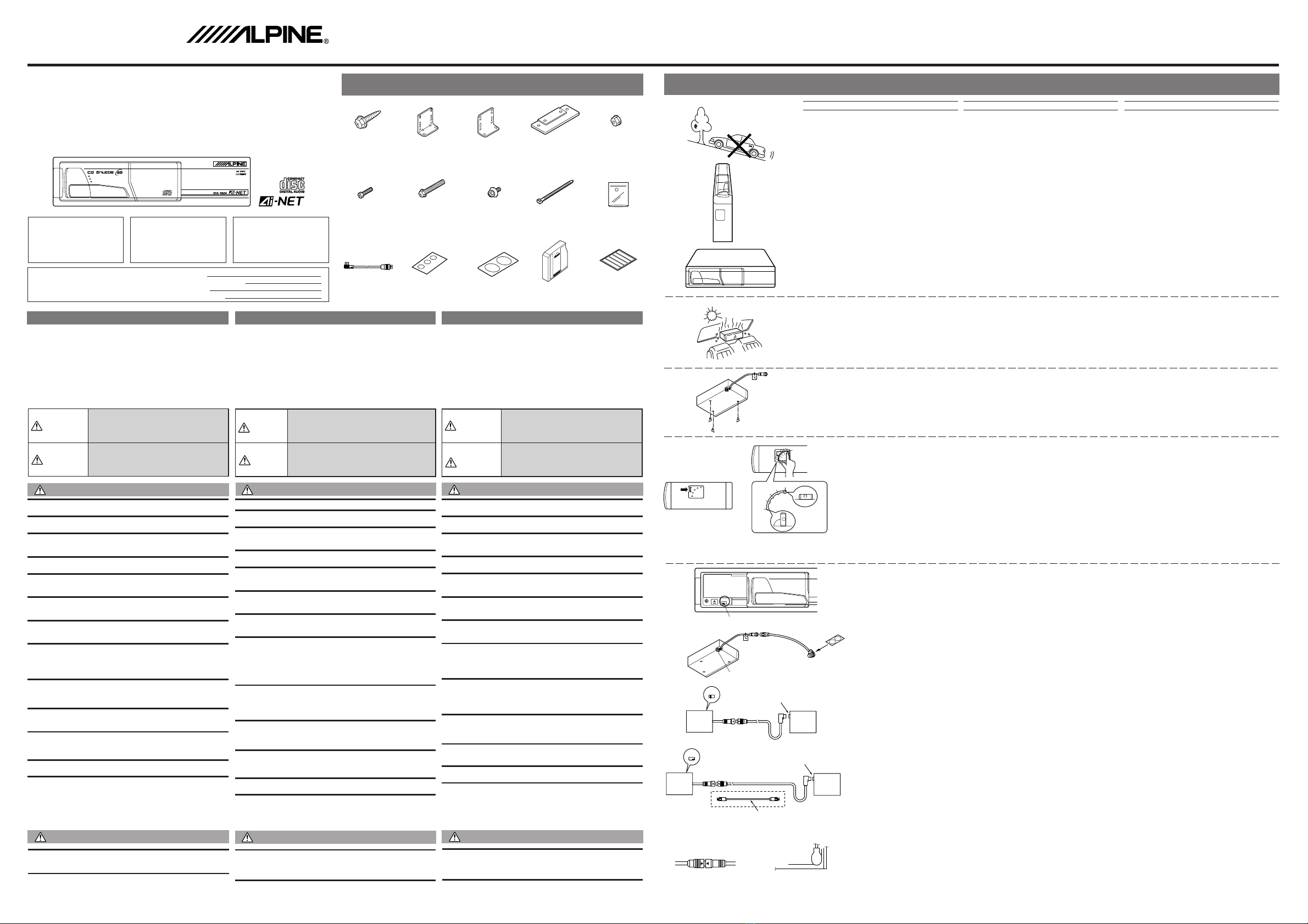
CAUTION:
Do not install the Shuttle near the vehicle's fuel tank. This will
prevent the mounting screws from damaging the tank.
Never install the Shuttle on the rear deck or front dashboard
ofthecar.The temperatures causedbydirect sunlight atthese
locations can reach extremes that could cause permanent
damage to the Shuttle. The Alpine Warranty will be voided in
cases where this caution has been ignored and results in
damage to the Shuttle.
ATTENTION:
N'installez pas le changeur (Shuttle) près du réservoir d'es-
sencedeI'automobile. Ceci empêcheraqueles visdemontage
endommagent le réservoir.
N'installezjamaislechangeur (Shuttle) sur laplagearrière ou
sur le tableau de bord avant d'une automobile. Les tempéra-
turesoccasionnéespar lesrayonsdirects dusoleilpeuvent être
extrêmes et peuvent endommager le changeur de façon per-
manente. La garantie Alpine sera annulée si vous ne tenez
aucun compte de cette précaution et le changeur en résulte
endommagé.
PRUDENCIA:
No instale el cambiador (Shuttle) cerca del depósito de com-
bustibledelvehículo.Esto evitará quelostornillos de montaje
dañen el depósito.
Nunca instale el cambiador en la repisa trasera o en el tablero de
instrumentos delantero del automóvil. La temperatura causada
por la luz directa del sol en dichos lugares puede ser extrema y
pude causar daños permanentes al cambiador. La garantía Alpine
perderá su validez si no tiene en cuenta esta precaución y el cam-
biador (Shuttle) resulta dañado por tal causa.
Verrouillage en vue du transport
Trois verrous ont été fixés sous le changeur pour
protéger le changeur lors de l'expédition. Enlevez
ces verrous avant d'utiliser le changeur et conser-
vez-les dans le sac de plastique attaché au connec-
teur du changeur.
Fiadores de transporte
En la parte inferior del cambiador han sido provis-
tos tres fiadores de transporte para protección
durante el transporte. Quite estos fiadores antes
de usar el aparato. Guarde los fiadores de trans-
porte en la bolsa plástica sujeta al conector del
cambiador.
H
V
R
H
V
(H)
(V)
90°
90°
0°
67.5°
45°
22.5°0°(H)
(V)
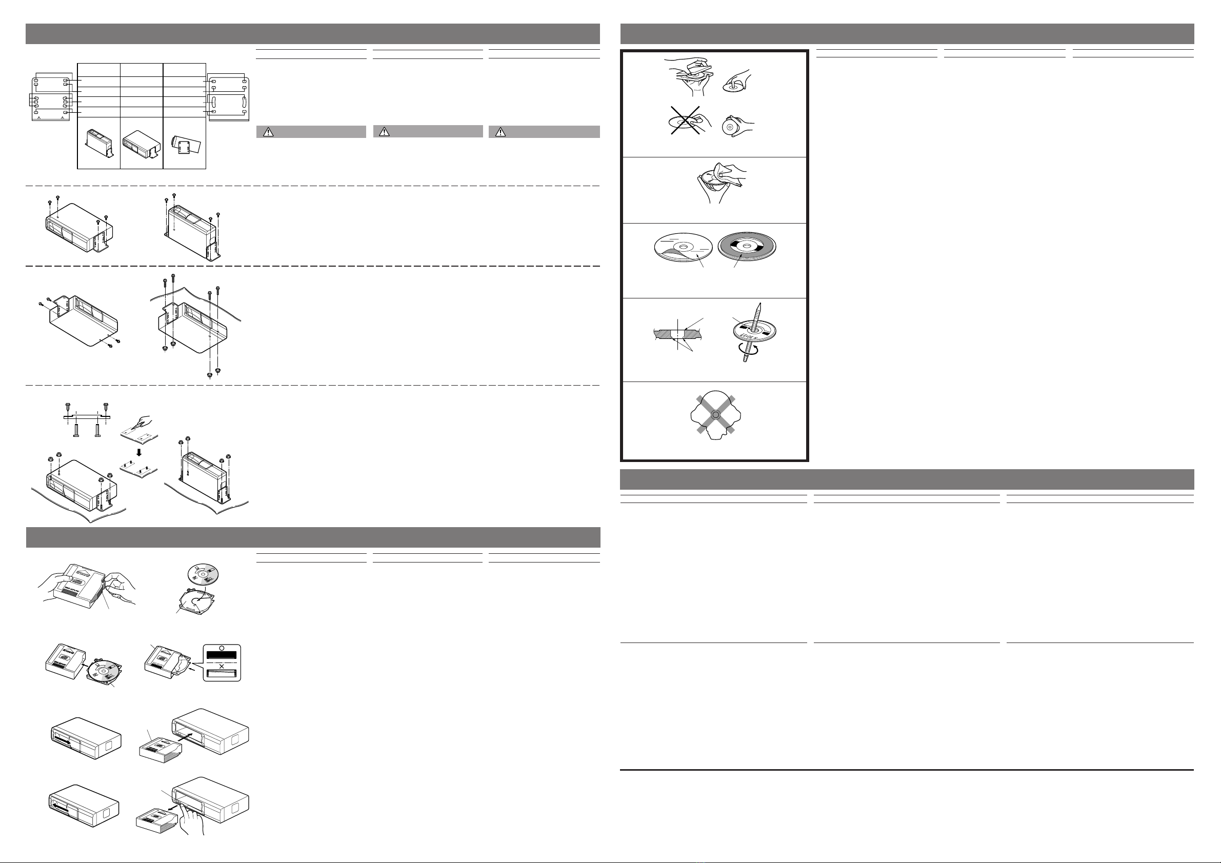
Instalación en el portaequipajes
Asegúrese de que el ángulo de montaje del Shuttle cor-
responda a una de las cinco posiciones preajustadas
(22,5˚ a 45˚ de la posición horizontal o vertical). El Shut-
tle viene preajustado de fábrica para ser montado
horizontalmente. Si usted desea instalarlo en cualquier
otro ángulo, cambie la configuración del resorte como
se muestra en las figuras.
1. Retire las cubiertas incluidas en el lado derecho e iz-
quierdodela unidadpresionandolos ganchosdelas
cubiertas en la dirección de la flecha.
2. Cambie la posición del resorte con su dedo. Utilice la
figura para determinar la posición del resorte más
adecuada al lugar de montaje elegido. Si la configu-
racióndelresorte es incorrecta,osi lasposicionesde
losresortesnosonlas mismaspara losladosizquier-
do y derecho, el mecanismo amortiguador no
funcionarácorrectamente.Esto hará queelCD Shut-
tle no opere debidamente.
3. Monte las cubiertas en los lados derecho e izquierdo
como estaban unidas originalmente.
Montage dans le coffre
Assurez-vousquel'angledemontagedel'installationdu
Shuttlecorrespondeàunedescinqpositionspréréglées
(22,5˚à45˚ dela positionhorizontaleou verticale).Étant
donné que le changeur (Shuttle) est préréglé en usine
pour un montage horizontal, si vous désirez installer le
changeur à un autre angle, vous devez changer la con-
figuration des ressorts comme indiqué aux figures.
1. Déplacer les couvercles se trouvant sur les cotés
gauche et droit de l'appareil en appuyant sur les cli-
quetsdescouverclesdanslesensindiquéparlaflèche.
2. Changezlapositiondesressortsavecvotredoigt.Uti-
lisez la figure pour déterminer la meilleure position
desressorts pourl'emplacement demontage choisi.
Si la configuration des ressorts est incorrecte ou si
leurspositionssontdifférentessur lagauche etsurla
droite. Le mécanisme amortisseur de choc ne fonc-
tionnerapas correctement.LechangeurCD(Shuttle)
pourrait ne pas donner le rendement escompté.
3. Monter les couvercles sur les cotés gauches et droit
tel qu'ils étaient fixés à l'origine.
Mounting in the Trunk
Makesurethe mountingangleof the Shuttleinstalla-
tion will fall within the five preset positions (22.5˚ to
45˚fromthe horizontalor verticalposition).The Shut-
tle is preset at the factory for horizontal mounting. If
you wish to install it at any other angle, change the
spring configuration as shown.
1. Remove the covers provided at both left and right
sides of the unit by pressing claws of the covers in
the direction shown by the arrow.
2. Changetheposition ofthespring withyourfinger.
Usethefigureto determine whichspringposition
wouldbebest suitedforyour chosenmounting lo-
cation.Ifthespringconfiguration isincorrect orthe
spring positions on the left and right sides are not
thesame,theshockabsorbing mechanismwillnot
function properly. This will prevent the CD Shut-
tle from operating at its best.
3. Mountthecovers at theleftand rightsidesasthey
were attached originally.
Fig. 1
Fig. 2
Fig. 3
Fig. 4
2
3
!
27
1 2
CHA-S624
Fig. 5 Fig. 6
Transport Locks
Three transport locks have been attached to the
bottom of the Shuttle for protection during ship-
ment. Remove these transport locks before using.
Keep the removed transport locks in the plastic bag
attached to the connector of Shuttle.
4
9
5
Caution
USE SPECIFIED ACCESSORY PARTS AND INSTALL THEM SECURELY. Use of other
than designated parts may damage this unit internally or may not securely install the
unit in place as parts that come loose may create hazards.
DO NOT INSTALL IN LOCATIONS WITH HIGH MOISTURE OR DUST. A high incidence
of moisture or dust that penetrates into this unit may cause smoke or fire.
1Digital/Analog Switch (Fig. 1)
The switch is used for switching the digital output/
analog output. Change the position with a pointed
object or sharp pencil, etc.
1: Analog output, 2: Digital output
Withthe systemnot usingthe digitaloutput, besure
to set the switch to "1" position.
2Ai-NET Cable (Included in the CHA-S624) (Fig. 2)
The Ai-NET Cable provided, allows connection to
anyAlpineAi-NETcompatible,CD ShuttleControl-
ler. Make sure that the "L" type connector of the
Ai-NET cable is attached to the Controller and the
straight connector is attached to the CHA-S624.
3Digital Output Terminal
This terminal may be used to connect the
CHA-S624tootherAlpine digitalproducts,incor-
porating optical digital inputs. These products
include a fiber optic cable that will plug directly
intotheDigital Output Terminalofthe CHA-S624.
4Input/Output Identification Label (Fig. 2)
The Ai-NET system has an input and an output.
The input connectors are Gray and outputs are
Black. Use the corresponding Input/Output ID
labels to maintain proper connections when ex-
tension cables are used.
• In combination with products not using optical
digital system (Fig. 3)
• In combination with products using optical digi-
tal system (Fig. 4)
5Ai-NET Input Connector
6Head Unit, etc. with Ai-NET System
7Optical Digital Unit with Ai-NET System
8Digital/Analog Switch Position: 1
9Digital/Analog Switch Position: 2
!Fiber Optic Cable (Included in the another facto-
ry unit or sold separately 4915/4916)
●Cautions for Connections
• Ai-NET Cable and CHA-S624 Cable (Fig. 5)
Match the arrows of Ai-NET cable and CHA-S624
cable.
• HeadunitwithAi-NET capability andAi-NETCa-
ble (Fig. 6)
Connect the Ai-NET cable as illustrated.
• Connectthecables by referringtothe illustration.
Incorrect connection may cause damage.
• Checkthecables andread theattachedlabels care-
fully.
1Commutateur numérique/analogique (Fig. 1)
Le commutateur est utilisé pour la commutation
delasortienumérique/sortieanalogique.Modifier
la position avec un objet ou un crayon pointu, etc.
1: sortie analogique, 2: sortie numérique
` Étant donné que le système n'utilise pas la sortie
numérique,s'assurerderéglerlecommutateursur
la position "1".
2Câble Ai-NET (fourni avec le CHA-S624) (Fig. 2)
Le câble Ai-NET fourni, permet la connexion à
n'importe quel contrôleur CD Shuttle Alpine com-
patibleAi-NET. S'assurerque leconnecteur detype
"L" du câble Ai-NET est fixé au contrôleur et que le
connecteur redressé est fixé au CHA-S624.
3Borne de sortie numérique
Cette borne peut être utilisée pour connecter le
CHA-S624 à d'autres appareils numériques Alpi-
ne, équipés d'entrées numériques optiques. Ces
appareilssontmunisd'uncâble àfibreoptiquequi
se branche directement dans la borne de sortie
numérique du CHA-S624.
4Marque d'identification d'entrée/sortie (Fig. 2)
Le système Ai-NET a une entrée et une sortie. Les
prises d'entrée sont grises et celles de sortie sont
noires.UtiliserlesmarquesID Entrée/Sortiecorre-
spondantes afin d'assurer des raccordements
correctsquandlescâblesd'extensionsontutilisés.
• Combiné à d'autres appareils n'utilisant pas le systè-
me numérique optique (Fig. 3)
• Combiné à d'autres appareils utilisant le système nu-
mérique optique (Fig. 4)
5Connecteur d'entrée Ai-NET
6Unité principale, etc. avec système Ai-NET
7Unité numérique optique avec système Ai-NET
8Positiondu commutateurnumérique/analogique: 1
9Positiondu commutateurnumérique/analogique: 2
!Câble à fibre optique (fourni en usine dans l'autre
unité ou vendu séparément 4915/4916)
●Précautions pour les connexions
• Câble Ai-NET et câble CHA-S624 (Fig. 5)
Faire correspondre les flèches d'un câble Ai-NET et d'un
câble CHA-S624.
• Unité pricipale avec système Ai-NET et câble Ai-
NET (Fig. 6)
Connecter le câble Ai-NET comme indiqué sur
l'illustration.
• Connecter les câbles en se reportant à l'illustration.
Une connexion incorrecte risque de provoquer des
dommages.
• Vérifierles câbleset lireattentivementlesautocollants.
1Interruptor digital/analógico (Fig. 1)
Este interruptor se utiliza para conmutar la salida
digital/analógica. Modifique la posición con un
objeto puntiagudo o un lápiz afilado, etc.
1: salida analógica, 2: salida digital
Debido a que el sistema no utiliza la salida digital,
asegúresedeajustarelinterruptoralaposición"1".
2Cable Ai-NET (incluido en el CHA-S624) (Fig. 2)
ElcableAi-NET, proporcionado,permitela conexión
a cualquierunidaddecontroldeShuttleCD,compati-
ble con el Ai-NET de Alpine. Aseqúrese de que el
conector de tipo "L" del cable Ai-NET sea fijado a la
unidad de control y de que el conector recto sea uni-
do al CHA-S624.
3Terminal de salida digital
Esteterminalpuedeser usado paraconectarelCHA-
S624 a otros productos digitales de Alpine, que
incorporen entradas digitales ópticas. Estos produc-
tosincluyenuncable de fibrasópticasque puede ser
insertado directamente en el terminal de salida digi-
tal del CHA-S624.
4Etiquetadeidentificacióndeentrada/salida(Fig.2)
ElsistemaAi-NET tieneunaentrada yunasalida. Los
conectores de entrada son grises y los de salida ne-
gros. Utilice las correspondientes etiquetas de
identificación de entrada y salida para mantener las
conexionescorrectascuandoseutilicenloscablesde
extensión.
• Combinado con otros aparatos que no utilicen el sis-
tema digital óptico (Fig. 3)
• Combinadoconotros aparatosque utilicenelsistema
digital óptico (Fig. 4)
5Conector de entrada Ai-NET
6Unidad principal, etc. con sistema Ai-NET
7Unidad digital óptica con sistema Ai-NET
8Posición del interruptor digital/analógico: 1
9Posición del interruptor digital/analógico: 2
!Cable de fibras ópticas (incluido de fábrica en la otra
unidad o vendido separadamente 4915/4916)
●Precauciones para las conexiones
• Cable Ai-NET y cable del CHA-S624 (Fig. 5)
Haga coincidir las flechas del cable Ai-NET y del cable
del CHA-S624.
• Uindadprincipal concapacidad Ai-NETy cableAi-NET
(Fig. 6)
Conecte el cable Ai-NET como se muestra en la ilus-
tración.
• Para conectar los cables vea la ilustratión. Una conex-
ión incorrecta puede causar daños.
• Revisecuidadosamente loscablesyleadetenidamente
sus etiquetas.
Dust Cover Label (L/R)/Eti-
quette de protection con-
tre la poussière (Gauche/
Droite)/Etiqueta de protec-
ción contra el polvo (iz-
quierda/derecha)
OPTICAL DIGITAL OUTPUT
DIGITAL SERVO
HIGH SPEED DISC CHANGE
COMPACT DISC CHANGER