CONTENTS/INHALT/TABLE
DE
MATIERES/SOMMARIO/INDICE/
INNEHALLSFORTECKNING
@
SYSTEM
CHARTS/SYSTEMAUFBAU/DIAGRAMMES
DU
SYSTEME/DISPOSIZIONI
DEL
SISTEMA/DIAGRAMAS
DEL
SISTEMA/SYSTEM-OVERSIKT
2.0.2.0...
200020
e
2,3
@
Fig.
1/ADD.
Toys
sees
eee
estes
es
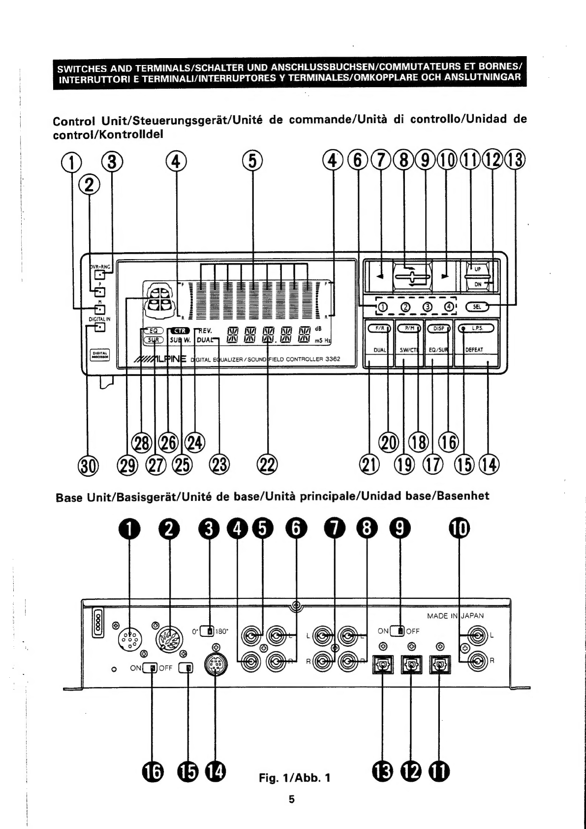
SWITCHES
AND
TERMINALS/SCHALTER
UND
ANSCHLUSSBUCHSEN/COMMUTATEURS
ET
BORNES/INTERRUTTORI
E
TERMINALI/INTERRUPTORES
Y
TERMINALES/
OMKOPPLARE
OCH
ANSLUTNINGAR
“ENGLISH”
INTRODUCTIONS.
i.cjekensuseeaiaces
6
PEAHORES
s
eeneecee
canes
Sone
ea
7
SWITCHES
AND
TERMINALS..........-.
8
OPERATION.......--.000eee
eee
9-18
PRECAUTIONS:
gviorcuis
Suede
nese
ate
19
CONNECTIONS
chmerreccta
coe
cy
20
—
27
INSTALLATIONS:
sia.
stte
cred
onsiesceee
28,
29
SPECIFICATIONS
wsausnaevenecthousas
30
“DEUTSCH”
EINFUHRUNG
..........2000seeeee
ees
31
MERKMALE.,
dec
ecveacuackeerentant
32
SCHALTER
UND
ANSCHLUSSBUCHSEN............505.
33
BEDIENUNG..............0.000-
34
—
43
ANSEHMUSSE
a
sccprututsvaanesicees
44-51
EINGAU
Ce
ts
accndoatiananetenr:
52
—
54
VORSICHTSMASSNAHMEN
.........---
54
TECHNISCHE
DATEN
...........-0
0055
55
“FRANGAIS”
INTRODUCTION
cinch
a
tcuee
tian
caine
56
CARACTERISTIQUES...........
000005.
57
COMMUTATEURS
ET
BORNES.........
58
FONCTIONNEMENT
...........-.
59
—
68
PRECAUMIONS,
ovata
eu
sateen
arias
acts
69
CONNEXIONS
2.0...
.00000
eee
70-77
INSTALLATION:
s3t.2.0..%
occxtar
eatin
78
—
80
SPECIFICATIONS
.....20.:ese0cesee
ees
80
Ba
teats
oh
craton
the
cha
Daten
et
et
ea
uae
erated
5
“ITALIANO”
INTRODUZIONE
..............00
0c
eee
81
CARATTERISTICHE............
00002
81,
82°
INTERRUTTORI
E
TERMINALI...........
83
FUNZIONAMENTO.............-.
84
—
93
COLLEGAMENTI................
94-101
INST
ALAZIONES
«0th
dree
ie
ar
102
—
104
PRECAUZION
45.6c00-ocua
soa
tee
aes
104
SPECIFICAZIONI:
4
chee
es
sare
a
de
ee
he
105
“ESPANOL”
INTRODUCCION
ecm
oxiartnsts
chutrace
oes
106
CARACTERISTICAS
...........005
106,
107
INTERRUPTORES
Y
TERMINALES
......
108
OPERACION
Gs
a
deles
eae
ls
109-118
PRECAUCIONES.............0
000000
119
CONEXIONES
&
2
sccvegaseetalen
120
—127
INS
TALACION:
b
ucetduedate®
oaues
128
—130
ESPECIFICACIONES...........
0.00005
130
“SVENSKA”
INTROBURKTION
35
¢..05.ce
lav
hewetien
aus
131
EGENSKAPER:.
«hc
s/oes
wean
eeebe
ove
132
OMKOPPLARE
OCH
ANSLUTNINGAR
..
.
133
MANOVRERING............00-
134-143
ANSLUTNINGAR.............-.
144-151
INSTALLATION.
acteces
i
stomeeute
152,153
FORSIKTIGHETSATGARDER
...........
154
SPECIFIKATIONER
............00
00
eee
155
@
CHARACTERISTIC
CURVES/CHARAKTERISTISCHE
ENTZERRERKURVEN/COURBES
CARACTERISTIQUES/CURVE
CARATTERISTICHE/CURVAS
CARACTERISTICAS/
FREKVENSKURVOR
occ
os
2
cus
oe
doe
aoe