Alstom MiCOM P50 Agile P15D User manual

MiCOM P50 Agile P15D
© - ALSTOM 2014. All rights reserved. Information contained in this document is indicative only. No representation or warranty is given or should be relied on that it
is complete or correct or will apply to any particular project. This will depend on the technical and commercial circumstances. It is provided without liability and is
subject to change without notice. Reproduction, use or disclosure to third parties, without express written authority, is strictly prohibited.
Technical Manual
Dual Powered overcurrent relay
Platform Hardware Version: A
Platform Software Version: 01
Publication Reference: P15D/EN M/B


P50 Agile P15D
1 Introduction
P15D/EN TM/B
1-1
INTRODUCTION
CHAPTER 1

1 Introduction
P50 Agile P15D
1-2
P15D/EN TM/B

P50 Agile P15D
1 Introduction
P15D/EN TM/B
1-3
1 CHAPTER OVERVIEW
This chapter consists of the following sections:
1Chapter Overview
2Introduction
2.1 Features
2.2 Functional Overview
2.3 Ordering information

1 Introduction
P50 Agile P15D
1-4
P15D/EN TM/B
2 INTRODUCTION
2.1 Features
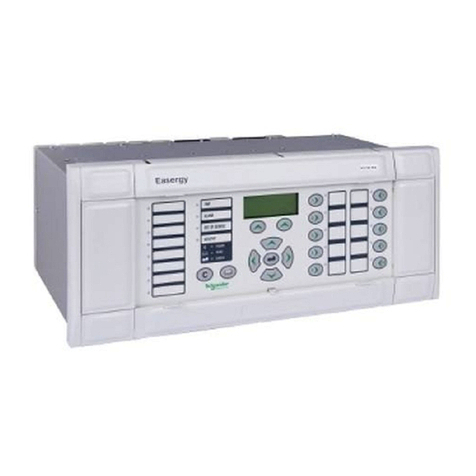
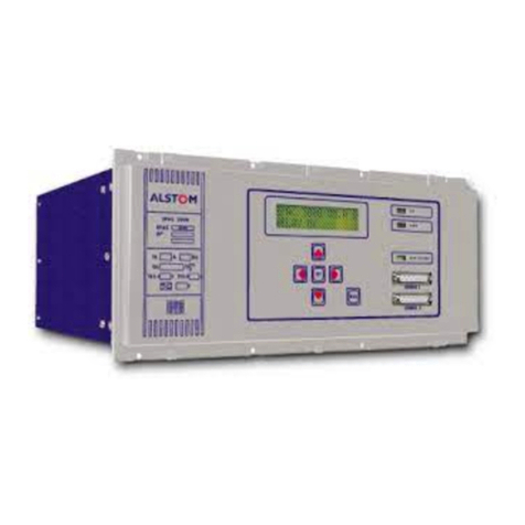
The P15D is a dual powered non-directional overcurrent and earth fault relay which provides
protection for applications where no external auxiliary power supply is available, or where the auxiliary
supply available does not guarantee the dependability required for protection applications. This relay
is mainly deployed in industrial installations, distribution network substations and most specifically in
Ring Main Unit (RMU) networks for monitoring and protection purposes.
The relay offers supervision functions including measurement, monitoring and recording functions.
Industry and utility protocols are available for transmitting relay data to a supervisory control system
via communication networks. The user-friendly operator interface facilitates easy reading of measured
values and simple configuration of the relay.
Protection & Control
•Timed and instantaneous phase and earth fault protection (3 independent stages)
•Wide range of IEC/IEEE curves
•Thermal overload protection
•Cold load pickup protection
•Inrush blocking
•4 Digital inputs
•2 Digital outputs
•1A/5A ordering option for CTs
•Low energy pulse output tripping for RMU
•Dual power supply option
•Internal battery for maintaining LCD/ communication during faults
•2 Setting groups
•Password protection
•Self-supervision & internal diagnostics
Measurement, Recording & Post fault analysis
•Metering of Phase & Neutral currents
•Measurement of thermal state
•Up to 100 time tagged event records
•Up to 5 disturbance records
•Battery-backed indication
Front Panel Interface
•4 LEDs for status indication
•Backlit LCD display (16 x 2)
•8 navigation keys for setting and interrogation
P50 Agile P15D 1 Introduction
P15D/EN TM/B 1-5
Communications
Front USB port for real-time data viewing, device setting, and upload/download.
Rear EIA (RS) 485 port for SCADA communication
Multiple protocols - Modbus/ IEC60870-5-103 (user selectable)
2.2 Functional Overview
ANSI FUNCTION P15D
50 Definite time overcurrent
50N Neutral/Earth definite time overcurrent
51 IDMT overcurrent
51N Neutral/Earth IDMT overcurrent
68 Inrush Blocking
49 Thermal Overload
37 Undercurrent detection (aux. power mode)
CLP Cold load pick-up
HMI
Back-Lit LCD display
8 x Touch Keys
4 x status LEDs
Communication
USB port
Modbus/IEC 60870-5-103 (RS485)
Binary Input/Output
Binary Input 4
Binary Output 2
Low energy pulse output for tripping
Energy output for external flag indicator
Analogue Input
Phase current input 3x1 ph
Phase current input 1x1 ph
General
Setting Groups 2
Self diagnostics
Measurements
Event records
Fault records
Disturbance records
Hardware
Auxiliary supply a. Internal from CT
b. External : 24-50V DC or
100-230V AC/DC (Option)
Climatic conditions Operating -25oC to +65oC
Storage -25oC to + 65oC
Housing IP 52

1 Introduction
P50 Agile P15D
1-6
P15D/EN TM/B
2.3 Ordering information
Figure 1: Ordering Information

SAFETY INFORMATION
CHAPTER 2

Safety Information
Pxxx
2

Pxxx
Safety Information
3
1 HEALTH AND SAFETY
Personnel associated with the equipment must be familiar with the contents of this Safety Information.
When electrical equipment is in operation, dangerous voltages are present in certain parts of the equipment.
Improper use of the equipment and failure to observe warning notices will endanger personnel.
Only qualified personnel may work on or operate the equipment. Qualified personnel are individuals who are:
● familiar with the installation, commissioning, and operation of the equipment and the system to which it
is being connected.
● familiar with accepted safety engineering practises and are authorised to energise and de-energise
equipment in the correct manner.
● trained in the care and use of safety apparatus in accordance with safety engineering practises
● trained in emergency procedures (first aid).
The documentation provides instructions for installing, commissioning and operating the equipment. It
cannot, however cover all conceivable circumstances. In the event of questions or problems, do not take any
action without proper authorisation. Please contact your local sales office and request the necessary
information.

Safety Information
Pxxx
4
2 SYMBOLS
Throughout this manual you will come across the following symbols. You will also see these symbols on
parts of the equipment.
Caution:
Refer to equipment documentation. Failure to do so could result in damage to
the equipment
Warning:
Risk of electric shock
Earth terminal. Note: This symbol may also be used for a protective conductor (earth) terminal if that
terminal is part of a terminal block or sub-assembly.
Protective conductor (earth) terminal
Instructions on disposal requirements
Note:
The term 'Earth' used in this manual is the direct equivalent of the North American term 'Ground'.

Pxxx
Safety Information
5
Caution:
All personnel involved in installing, commissioning, or servicing this equipment
must be familiar with the correct working procedures.
Caution:
Consult the equipment documentation before installing, commissioning, or
servicing the equipment.
Caution:
Always use the equipment as specified. Failure to do so will jeopardise the
protection provided by the equipment.
Warning:
Removal of equipment panels or covers may expose hazardous live parts. Do
not touch until the electrical power is removed. Take care when there is
unlocked access to the rear of the equipment.
Warning:
Isolate the equipment before working on the terminal strips.
Warning:
Use a suitable protective barrier for areas with restricted space, where there is a
risk of electric shock due to exposed terminals.
Caution:
Disconnect power before disassembling. Disassembly of the equipment may
expose sensitive electronic circuitry. Take suitable precautions against
electrostatic voltage discharge (ESD) to avoid damage to the equipment.
3 INSTALLATION, COMMISSIONING AND SERVICING
3.1 LIFTING HAZARDS
Many injuries are caused by:
● Lifting heavy objects
● Lifting things incorrectly
● Pushing or pulling heavy objects
● Using the same muscles repetitively
Plan carefully, identify any possible hazards and determine how best to move the product. Look at other
ways of moving the load to avoid manual handling. Use the correct lifting techniques and Personal Protective
Equipment (PPE) to reduce the risk of injury.
3.2 ELECTRICAL HAZARDS

Safety Information
Pxxx
6
Caution:
NEVER look into optical fibres or optical output connections. Always use optical
power meters to determine operation or signal level.
Caution:
Testing may leave capacitors charged to dangerous voltage levels. Discharge
capacitors by rediucing test voltages to zero before disconnecting test leads.
Caution:
Operate the equipment within the specified electrical and environmental limits.
Caution:
Before cleaning the equipment, ensure that no connections are energised. Use a
lint free cloth dampened with clean water.
Note:
Contact fingers of test plugs are normally protected by petroleum jelly, which should not be removed.
3.3 UL/CSA/CUL REQUIREMENTS
The information in this section is applicable only to equipment carrying UL/CSA/CUL markings.
Caution:
Equipment intended for rack or panel mounting is for use on a flat surface of a
Type 1 enclosure, as defined by Underwriters Laboratories (UL).
Caution:
To maintain compliance with UL and CSA/CUL, install the equipment using UL/
CSA-recognised parts for: cables, protective fuses, fuse holders and circuit
breakers, insulation crimp terminals, and replacement internal batteries.
3.4 FUSING REQUIREMENTS
Caution:
Where UL/CSA listing of the equipment is required for external fuse protection, a
UL or CSA Listed fuse must be used for the auxiliary supply. The listed
protective fuse type is: Class J time delay fuse, with a maximum current rating
of 15 A and a minimum DC rating of 250 V dc (for example type AJT15).

Pxxx
Safety Information
7
Caution:
Where UL/CSA listing of the equipment is not required, a high rupture capacity
(HRC) fuse type with a maximum current rating of 16 Amps and a minimum dc
rating of 250 V dc may be used for the auxiliary supply (for example Red Spot
type NIT or TIA).
For P50 models, use a 1A maximum T-type fuse.
For P60 models, use a 4A maximum T-type fuse.
Caution:
Digital input circuits should be protected by a high rupture capacity NIT or TIA
fuse with maximum rating of 16 A. for safety reasons, current transformer
circuits must never be fused. Other circuits should be appropriately fused to
protect the wire used.
Caution:
CTs must NOT be fused since open circuiting them may produce lethal
hazardous voltages
Warning:
Terminals exposed during installation, commissioning and maintenance may
present a hazardous voltage unless the equipment is electrically isolated.
Caution:
Tighten M4 clamping screws of heavy duty terminal block connectors to a
nominal torque of 1.3 Nm.
Tighten captive screws of terminal blocks to 0.5 Nm minimum and 0.6 Nm
maximum.
Caution:
Always use insulated crimp terminations for voltage and current connections.
Caution:
Always use the correct crimp terminal and tool according to the wire size.
Caution:
Watchdog (self-monitoring) contacts are provided to indicate the health of the
device on some products. We strongly recommend that you hard wire these
contacts into the substation's automation system, for alarm purposes.
3.5 EQUIPMENT CONNECTIONS

Safety Information
Pxxx
8
Caution:
Earth the equipment with the supplied PCT (Protective Conductor Terminal).
Caution:
Do not remove the PCT.
Caution:
The PCT is sometimes used to terminate cable screens. Always check the PCT’s
integrity after adding or removing such earth connections.
Caution:
Use a locknut or similar mechanism to ensure the integrity of stud-connected
PCTs.
Caution:
The recommended minimum PCT wire size is 2.5 mm² for countries whose
mains supply is 230 V (e.g. Europe) and 3.3 mm² for countries whose mains
supply is 110 V (e.g. North America). This may be superseded by local or
country wiring regulations.
For P60 products, the recommended minimum PCT wire size is 6 mm². See
product documentation for details.
Caution:
The PCT connection must have low-inductance and be as short as possible.
Caution:
All connections to the equipment must have a defined potential. Connections
that are pre-wired, but not used, should be earthed, or connected to a common
grouped potential.
Caution:
Check voltage rating/polarity (rating label/equipment documentation).
Caution:
Check CT circuit rating (rating label) and integrity of connections.
Caution:
Check protective fuse or miniature circuit breaker (MCB) rating.
3.6 PROTECTION CLASS 1 EQUIPMENT REQUIREMENTS
3.7 PRE-ENERGISATION CHECKLIST

Pxxx
Safety Information
9
Caution:
Check integrity of the PCT connection.
Caution:
Check voltage and current rating of external wiring, ensuring it is appropriate for
the application.
3.8 PERIPHERAL CIRCUITRY
Warning:
Do not open the secondary circuit of a live CT since the high voltage produced
may be lethal to personnel and could damage insulation. Short the secondary of
the line CT before opening any connections to it.
Note:
For most Alstom equipment with ring-terminal connections, the threaded terminal block for current transformer
termination is automatically shorted if the module is removed. Therefore external shorting of the CTs may not be
required. Check the equipment documentation and wiring diagrams first to see if this applies.
Caution:
Where external components such as resistors or voltage dependent resistors
(VDRs) are used, these may present a risk of electric shock or burns if touched.
Warning:
Take extreme care when using external test blocks and test plugs such as the
MMLG, MMLB and P990, as hazardous voltages may be exposed. Ensure that CT
shorting links are in place before removing test plugs, to avoid potentially lethal
voltages.
3.9 UPGRADING/SERVICING
Warning:
Do not insert or withdraw modules, PCBs or expansion boards from the
equipment while energised, as this may result in damage to the equipment.
Hazardous live voltages would also be exposed, endangering personnel.
Caution:
Internal modules and assemblies can be heavy and may have sharp edges. Take
care when inserting or removing modules into or out of the IED.

Safety Information
Pxxx
10
4 DECOMMISSIONING AND DISPOSAL
Caution:
Before decommissioning, completely isolate the equipment power supplies
(both poles of any dc supply). The auxiliary supply input may have capacitors in
parallel, which may still be charged. To avoid electric shock, discharge the
capacitors using the external terminals before decommissioning.
Caution:
Avoid incineration or disposal to water courses. Dispose of the equipment in a
safe, responsible and environmentally friendly manner, and if applicable, in
accordance with country-specific regulations.

Pxxx
Safety Information
11
5 STANDARDS COMPLIANCE
Compliance with the European Commission Directive on EMC and LVD is demonstrated using a Technical
File.
5.1 EMC COMPLIANCE: 2004/108/EC
Compliance with EN60255-26:2009 was used to establish conformity.
5.2 PRODUCT SAFETY: 2006/95/EC
Compliance with EN60255-27:2005 was used to establish conformity.
Protective Class
IEC 60255-27: 2005 Class 1 (unless otherwise specified in equipment documentation). This equipment
requires a protective conductor (earth) to ensure user safety.
Installation category
IEC 60255-27: 2005 Overvoltage Category 3. Equipment in this category is qualification tested at 5kV peak,
1.2/50
m
S,
500 Ohms, 0.5 J, between all supply circuits and earth and also between independent circuits.
Environment
IEC 60255-27: 2005, IEC 60255-26:2009. The equipment is intended for indoor use only. If it is required for
use in an outdoor environment, it must be mounted in a specific cabinet or housing which will enable it to
meet the requirements of IEC 60529 with the classification of degree of protection IP54.
5.3 R&TTE COMPLIANCE
Radio and Telecommunications Terminal Equipment (R&TTE) directive 99/5/EC.
Conformity is demonstrated by compliance to both the EMC directive and the Low Voltage directive, to zero
volts.
5.4 UL/CUL COMPLIANCE
If marked with this logo, the product is compliant with the requirements of the Canadian and USA
Underwriters Laboratories.
The relevant UL file number and ID is shown on the equipment.
5.5 ATEX COMPLIANCE
If marked with the logo, the equipment is compliant with article 192 of European directive 94/9/EC. It is
approved for operation outside an ATEX hazardous area. It is however approved for connection to Increased
Safety, "Ex e", motors with rated ATEX protection, equipment category 2, to ensure their safe operation in
gas zones 1 and 2 hazardous areas.

Safety Information
Pxxx
12
Equipment with this marking is not itself suitable for operation within a potentially explosive
atmosphere.
Compliance demonstrated by Notified Body Type Examination Certificate.
ATEX Potentially Explosive Atmospheres directive 94/9/EC for equipment.
Table of contents
Other Alstom Relay manuals

Alstom
Alstom MiCOM P846 User manual

Alstom
Alstom EPAC 3100 User manual

Alstom
Alstom Micom P14DB User manual

Alstom
Alstom EPAC 3100 Assembly instructions

Alstom
Alstom MCAG 14 User manual

Alstom
Alstom P50 Agile User manual

Alstom
Alstom MBCH User manual

Alstom
Alstom MX3IPG2A User manual

Alstom
Alstom MCAG User manual

Alstom
Alstom MiCOM P54 Series User manual
Popular Relay manuals by other brands

ABB
ABB Rellon 620 Series Communication protocol manual

Moeller
Moeller ZB65 Series Hardware and engineering

Kumu Networks
Kumu Networks Self Backhaul UE Relay user guide

Schweitzer Engineering Laboratories
Schweitzer Engineering Laboratories SEL-749M instruction manual

Woodward
Woodward MFR 11 manual

Siemens
Siemens SIRIUS 3UG4511 A Series operating instructions