Configuration
Inputs and outputs
• 8 or 16 user programmable,
optically isolated inputs
depending on the model selected.
• 13, 16, 26 or 32 user
programmable normally open
output contacts depending on the
model selected.
• 3, 6 or 12 normally open trip
contacts depending on the model
selected. These contacts may be
connected directly to the coil of
the circuit breaker.
• 1 or 2 normally open reclose
contacts depending on the model
selected. These contacts may be
connected directly to the coil of
the circuit breaker.
• 1 or 2 normally closed contacts,
depending on the model selected,
for watchdog alarm.
Alternative setting groups
Four sets of setting groups are
provided and stored in a non-
volatile memory. They can be used
to change the relay’s setting to
cover abnormal operating
conditions. The setting groups can
be selected locally via the front
panel display or WinEPAC
software, or remotely via the relay’s
communication system. Two inputs
can be allocated to the selection of
setting groups allowing them to be
changed by means of an external
system.
Ancillary Functions
The ancillary functions allow the
equipment to be used in specific
applications.
Instrumentation
The instrumentation functions of the
equipment can be accessed locally
via the relay’s front panel display or
the WinEPAC software, or remotely
via its communication system.
Values of frequency, phase currents
and voltages, active and reactive
power, the direction of the load
current, and the status of the relay’s
inputs and outputs are displayed.
Fault reports
When a fault occurs, causing a
relay to trip, a fault report is created
and stored in non-volatile memory.
t is possible to view via the relay’s
front panel or the WinEPAC
software, or print out, any or all of
the last ten fault reports.
Each fault report includes time
tagged details of the faulted phases,
trip type and fault location (fault
distance and apparent resistance).
Additionally, information on the
system frequency, fault currents and
voltages values.
Disturbance records
The internal disturbance recorder
has 8 analogue channels to record
current and voltage inputs to the
relay and up to 32 digital channels
to record the status of the
input/output relays. Data
compression allows the recording
and storage in non-volatile memory
of an average of forty 5-second
events. The information in the
disturbance recorder is accessed on
a personal computer connected to
the relay’s front panel or via the
communication system to provide a
graphical display and to conduct in-
depth fault analysis, using WinTPE
software.
Fault location
The fault location report provides
information about the distance to the
fault and the fault resistance. The
distance to the fault is in miles,
kilometres, ohms or as a percentage
of line length.
Fault location can be calculated
both for single and parallel lines.
Power-on diagnostics and self
monitoring
The relay continuously runs self-
checks. n the event of a failure of a
device, an alarm is triggered and a
self-diagnostics system enables
quick and easy trouble-shooting.
Hardware description
The EPAC is a fully numerical relay
providing:
• input circuit with anti-aliasing
filters.
• acquisition of residual quantities
allowing constant monitoring of
sampled values.
• 16-bit sampling of current values
and 12-bit sampling of voltage
values.
• filtering and computing of derived
quantities and protection
algorithms by a real-time signal
processor.
• tripping logic, management of
logic acquisitions and signals.
The oscillography, communication
and user interface dialogue are
managed by a special board
having a R SC microprocessor
NTEL 960.
User interface
The EPAC is programmed and
operated through its key-pad and
display, or through its RS-232 link
on the front panel of the unit, or via
the communications unit from a
personal computer running the
programming software WinEPAC.
User interface with WinEPAC
WinEPAC software is run on the
WindowsTM interface of which it
uses the graphic capabilities to their
fullest. All the functions are clearly
labelled and grouped by theme
screens. WinEPAC is a very
intuitive application and it is quick
and easy to learn.
Front panel user interface
Dialogue through the front panel
display offers the same features as
with the WinEPAC software.
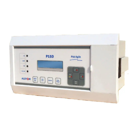
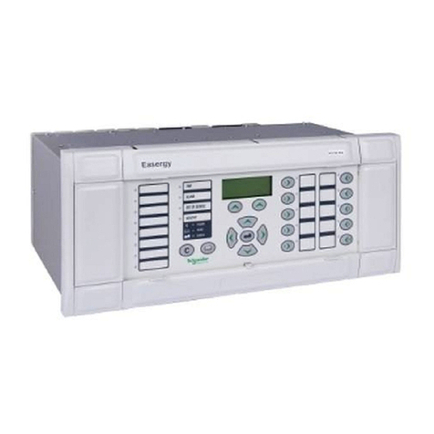
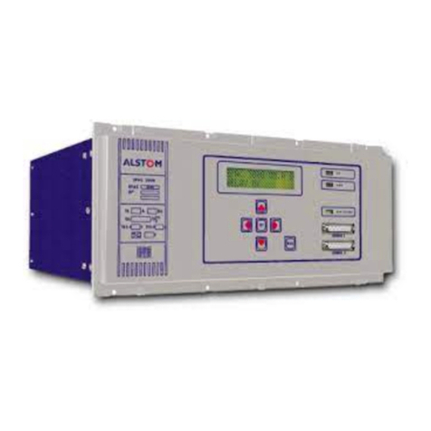
Functions are selected using six keys
on the key-pad. The display is a 2
line, 16 character back-lit LCD
screen.
8
Figure 11.
WinTPE software (WinANALYSE)
Figure 12.
WinEPAC software
Figure 13.
Front panel display
