CRH CRL SS96 User manual

GLASS DRILL INSTRUCTION MANUAL
PRODUCT MANUAL
crlaurence.com
C.R. Laurence Co., Inc. •2503 E. Vernon Ave., Los Angeles, CA 90058 •1.800.421.6144 •crlaurence.com
NOVEMBER 2020
AVDB3413_11/20
SS96 Hot Melt Unit
Cat. No. SS96

GLASS DRILL INSTRUCTION MANUAL
PRODUCT MANUAL
crlaurence.com
C.R. Laurence Co., Inc. •2503 E. Vernon Ave., Los Angeles, CA 90058 •1.800.421.6144 •crlaurence.com
NOVEMBER 2020
P. 2
□To avoid personal injury and damage to equipment and property, read the product manual completely before installing,
operating or servicing this equipment.
□Follow all safety warnings located on this product and in the product manual. Consult the safety precautions section of
the product manual for an explanation of all safety symbols used on this equipment.
□Retain the product manual for the life of this product.
□After reading this manual, if further assistance is needed, contact your factory authorized sales or service representative.
WARNING:
NOTE CONCERNING ILLUSTRATIONS: All illustrations within this product manual should be considered as general
representations of the parts or assemblies depicted, and should not serve as mechanical drawings, nor be consulted
for scope or scale. They are for reference only.
12 SS96 Hot Melt Unit 19600-135 Rev. B 10/26/00
DANGER: To avoid personal injury, follow all
safety labels. Failure to properly operate and
maintain equipment can lead to serious injury.
•Wear protective clothing, safety goggles and
safety gloves. Hot melt materials can cause
severe burns resulting in disfigurement or
blindness.
•Use only manufacturer recommended materials
in this system. Fire, explosion, personal injury,
property and equipment damage can result if
improper or unsafe materials are used.
•Disconnect electrical power from external
source to melt unit before undertaking
maintenance or troubleshooting. Failure to
disconnect power can result in fatal electrical
shock.
•Depressurize system before performing any
maintenance to pump, pump filter, flow control
valve or hose. Turn pump switch off and
depress trigger on handgun until there is no
flow. Air trapped in the system or in a
component can form a pressure pocket.
Loosen fittings cautiously. Adhesive under
pressure can cause severe burns and
blindness.
•Always read the manufacturer’s recommended
use of the material.
5.2 Startup Instructions
1. Become familiar with Section 5.1, Controls and Indicators.
2. Install melt unit as specified in Section 4, Installation.
3. Fill tank with hot melt material.
4. Turn melt unit on and allow sufficient warmup time for hot
melt material to thoroughly melt.
5. Align motor on receipt of a new unit or after transportation.
a. Loosen four screws holding motor pan to side of melt
unit.
b. Heat melt unit and run motor. This centers the motor.
c. With motor running, tighten four screws in a crisscross
pattern.
6. Set hose and tank temperatures to desired settings. Lower
settings increase pot life of the material. Materials degrade
over time due to oxidation.
7. To prevent motor stalling, adjust flow control valve to the
minimum flow requirement.
!

GLASS DRILL INSTRUCTION MANUAL
PRODUCT MANUAL
crlaurence.com
C.R. Laurence Co., Inc. •2503 E. Vernon Ave., Los Angeles, CA 90058 •1.800.421.6144 •crlaurence.com
NOVEMBER 2020
P. 3
TABLE OF CONTENTS
1 SAFETY PRECAUTIONS FOR HOT MELT APPLICATOR EQUIPMENT ..............................................................................5
1.1 INTENDED USE.......................................................................................................................................................................................... 5
1.2 PERSONAL SAFETY............................................................................................................................................................................... 5
1.3 ELECTRICAL SAFETY ...........................................................................................................................................................................5
1.4 EMERGENCY POWER DISCONNECT..........................................................................................................................................6
1.5 FOLLOW DIRECTIONS..........................................................................................................................................................................6
1.6 SAFETY SYMBOLS AND SIGNAL WORDS ...............................................................................................................................6
2 INTRODUCTION .....................................................................................................................................................................................................7
2.1 DESCRIPTION.............................................................................................................................................................................................7
2.2 FEATURES.....................................................................................................................................................................................................7
3 SPECIFICATIONS ....................................................................................................................................................................................................8
3.1 ELECTRICAL ............................................................................................................................................................................................... 8
3.2 PHYSICAL .....................................................................................................................................................................................................8
3.3 PERFORMANCE........................................................................................................................................................................................8
3.4 ENVIRONMENTAL ...................................................................................................................................................................................8
3.5 DIMENSIONS...............................................................................................................................................................................................9
4 INSTALLATION.........................................................................................................................................................................................................9
4.1 SETUP........................... ...................................................................................................................................................................................9
4.2 COMPONENT INSTALLATION .........................................................................................................................................................9
4.3 ELECTRICAL CIRCUITS AND WIRING .........................................................................................................................................10
4.3.1 POWER CORD........................... .................................................................................................................................................................10
4.3.2 SWITCHED HANDGUN PUMP MOTOR CIRCUIT...................................................................................................................10
5 OPERATION................................................................................................................................................................................................................11
5.1 CONTROLS AND INDICATORS........................... ..................................................................................................................................11
[1] SYSTEM POWER SWITCH/CIRCUIT BREAKER AND INDICATOR .............................................................................11
[2] PUMP ON/OFF BREAKER SWITCH.............................................................................................................................................11
[3] TANK THERMOMETER........................................................................................................................................................................11
[4] TANK HEATING INDICATOR ............................................................................................................................................................ 11
[5] TANK OVER TEMPERATURE INDICATOR................................................................................................................................ 11
[6] APPLICATOR.............................................................................................................................................................................................11
[7] FLOW CONTROL VALVE (NOT SHOWN)................................................................................................................................ 11
[8] TANK TEMPERATURE CONTROLLER (NOT SHOWN)...................................................................................................11
[9] HOSE TEMPERATURE CONTROLLER (NOT SHOWN)..................................................................................................11

GLASS DRILL INSTRUCTION MANUAL
PRODUCT MANUAL
crlaurence.com
C.R. Laurence Co., Inc. •2503 E. Vernon Ave., Los Angeles, CA 90058 •1.800.421.6144 •crlaurence.com
NOVEMBER 2020
P. 4
TABLE OF CONTENTS (CONT.)
5.2 STARTUP INSTRUCTIONS ..................................................................................................................................................................12
5.3 ADJUSTMENTS........................................................................................................................................................................................12
5.3.1 TANK TEMPERATURE CONTROLLER........................................................................................................................................12
5.3.2 HOSE TEMPERATURE CONTROLLER ......................................................................................................................................13
5.3.3 ADHESIVE FLOW ADJUSTMENT...................................................................................................................................................13
6 MAINTENANCE........................................................................................................................................................................................................14
6.1 PREVENTIVE MAINTENANCE..........................................................................................................................................................15
6.1.1 MONTHLY INSPECTION PROCEDURE.......................................................................................................................................15
7 TROUBLESHOOTING..........................................................................................................................................................................................15
8 REPAIR AND REPLACEMENT........................................................................................................................................................................17
8.1 HOSE REPLACEMENT..........................................................................................................................................................................17
8.1.1 REMOVAL OF EXISTING HOSE .......................................................................................................................................................17
8.1.2 INSTALLATION OF NEW HOSE........................................................................................................................................................18
8.2 HOSE CONTROLLER REPLACEMENT.......................................................................................................................................19
8.3 PUMP AND FLOW CONTROL REPLACEMENT ....................................................................................................................20
8.4 PUMP MOTOR REPLACEMENT......................................................................................................................................................21
8.5 TANK TEMPERATURE CONTROLLER REPLACEMENT...................................................................................................22
8.6 TANK HEATER REPLACEMENT.......................................................................................................................................................23
9 PARTS LIST ...............................................................................................................................................................................................................24
9.1 SS96 ASSEMBLY DRAWING............................................................................................................................................................. 24
9.2 FLOW CONTROL VALVE ASSEMBLY...........................................................................................................................................25
9.3 V1 PUMP ASSEMBLY...............................................................................................................................................................................26
9.4 MOTOR ASSEMBLY ...............................................................................................................................................................................27
9.5 L2 HANDGUN NOZZLES. ...................................................................................................................................................................28
9.6 RECOMMENDED SPARES...................................................................................................................................................................29

GLASS DRILL INSTRUCTION MANUAL
PRODUCT MANUAL
crlaurence.com
C.R. Laurence Co., Inc. •2503 E. Vernon Ave., Los Angeles, CA 90058 •1.800.421.6144 •crlaurence.com
NOVEMBER 2020
P. 5
1 . SAFETY PRECAUTIONS FOR HOT MELT APPLICATOR EQUIPMENT
This manual contains important safety information and instructions. Failure to comply with these instructions can result in
death, injury or permanent damage to this equipment and will void the warranty.
1.1 Intended Use
This equipment is designed for use with standard adhesive and sealant materials with flash points above 232 °C (450 °F).
Use of flammable material or material not compatible with the specifications of this equipment can cause injury to opera-
tor and damage to equipment.
The manufacturer has designed this equipment for safe operation. Specified models are in compliance with EN 60204-
1:1997. However, heated thermoplastics and other hot melt materials are dangerous and care must be exercised to ensure
operational safety. Handling must be in accordance with hot melt manufacturer specifications. Never exceed the maximum
application temperature recommended by the adhesive manufacturer.
Dispose of hot melt properly. Refer to the Safety Data Sheet (SDS) of the hot melt for recommended disposal methods.
1.2 Personal Safety
Wear the following protection when working on or around this equipment:
Always wear heat resistant gloves rated to 205 °C (400 °F) and allow all system temperatures to stabilize below 193 °C
(380 °F) before servicing. Properly ventilate equipment according to MSDS of equipment.
Trained operators and service technicians should be aware of exposed surfaces of the unit that cannot be practically
safeguarded. These exposed surfaces may be hot and take time to cool after the unit has been operating.
Keep parts of the body away from rotating parts. Do not wear loose articles of clothing when operating or servicing units
with rotating parts. Remove wristwatches, rings, necklaces, or other jewelry and cover or pin up long hair before performing
any work on or with the unit.
Trained operators may perform only external equipment adjustments. Trained service technicians must perform internal
adjustments and service.
1.3 Electrical Safety
Determine voltage of this equipment before installation and confirm compatibility with available power. Equipment must
be connected to a properly grounded circuit and installed in accordance with all applicable electrical codes. Ground fault
protection must be provided in supply circuitry at site installation.
Models designed to EN60204-1: 1997 require power cords be approved to a harmonized (HAR) standard and rated for 70
°C (158 °F). A HAR approved Type B plug and strain relief for power cord are required to meet standard IEC 309. Power
conducting wires must be nominal 5.3 mm2 (10 AWG) maximum and nominal 2.1 mm2 (14 AWG) minimum.
SS96 Hot Melt Unit 19600-135 Rev. B 10/26/00 1
1 Safety Precautions for Hot Melt Applicator Equipment
This manual contains important safety information and instructions.
Failure to comply with these instructions can result in death, injury or
permanent damage to this equipment and will void the warranty.
1.1 Intended Use
This equipment is designed for use with standard adhesive and sealant
materials with flash points above 232 °C (450 °F). Use of flammable
material or material not compatible with the specifications of this
equipment can cause injury to operator and damage to equipment.
The manufacturer has designed this equipment for safe operation.
Specified models are in compliance with EN 60204-1:1997. However,
heated thermoplastics and other hot melt materials are dangerous and
care must be exercised to ensure operational safety. Handling must be in
accordance with hot melt manufacturer specifications. Never exceed the
maximum application temperature recommended by the adhesive
manufacturer.
Dispose of hot melt properly. Refer to the Materials Safety Data Sheet
(MSDS) of the hot melt for recommended disposal methods.
1.2 Personal Safety
Wear the following protection when working on or around this equipment:
Always wear heat resistant gloves rated to 205 °C (400 °F) and allow all
system temperatures to stabilize below 193 °C (380 °F) before servicing.
Properly ventilate equipment according to MSDS of equipment.
Trained operators and service technicians should be aware of exposed
surfaces of the unit that cannot be practically safeguarded. These
exposed surfaces may be hot and take time to cool after the unit has
been operating.
Keep parts of the body away from rotating parts. Do not wear loose
articles of clothing when operating or servicing units with rotating parts.
Remove wristwatches, rings, necklaces, or other jewelry and cover or pin
up long hair before performing any work on or with the unit.
Trained operators may perform only external equipment adjustments.
Trained service technicians must perform internal adjustments and
service.
1.3 Electrical Safety
Determine voltage of this equipment before installation and confirm
compatibility with available power. Equipment must be connected to a
properly grounded circuit and installed in accordance with all applicable
electrical codes. Ground fault protection must be provided in supply
circuitry at site installation.
Models designed to EN60204-1: 1997 require power cords be approved
to a harmonized (HAR) standard and rated for 70 °C (158 °F). A HAR
approved Type B plug and strain relief for power cord are required to
meet standard IEC 309. Power conducting wires must be nominal
5.3 mm2(10 AWG) maximum and nominal 2.1 mm2(14 AWG) minimum.
1.4 Emergency Power Disconnect
In the event of a malfunction, turn off power to the equipment at the
power off switch and remove source power to the system at the nearest
main disconnect.
1.5 Follow Directions
Read the product manual thoroughly before installation, operation or
maintenance. Failure to do so can result in a serious accident or
equipment malfunction. The manufacturer will not be held liable for
injuries or damage caused by misuse of this equipment.
Wear Safety Goggles
Wear Heat-Resistant
Safety Gloves
Wear Protective Clothing
Table of contents
Other CRH Industrial Equipment manuals

CRH
CRH Leviat HALFEN HBB User manual

CRH
CRH Leviat HALFEN DEHA HA-N User manual

CRH
CRH Leviat HALFEN DEHA 6003 User manual

CRH
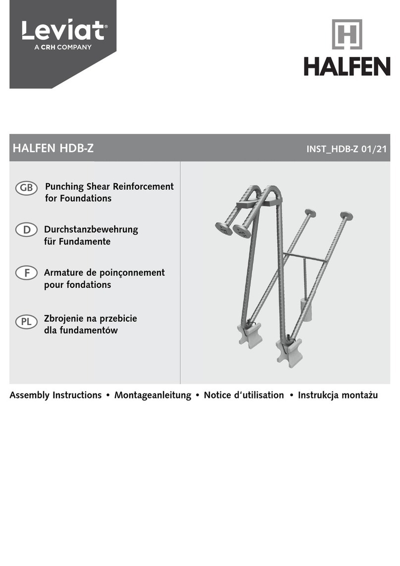
CRH Leviat HALFEN HDB-Z User manual

CRH
CRH Leviat HALFEN MBT User manual

CRH
CRH Leviat Halfen HCC User manual

CRH
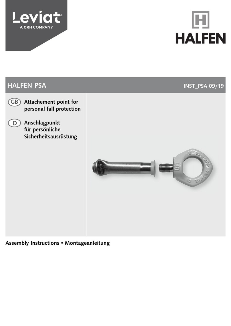
CRH Leviat HALFEN PSA User manual

CRH
CRH Leviat Ancon 2000 User manual

CRH
CRH Leviat HALFEN DETAN-S User manual

CRH
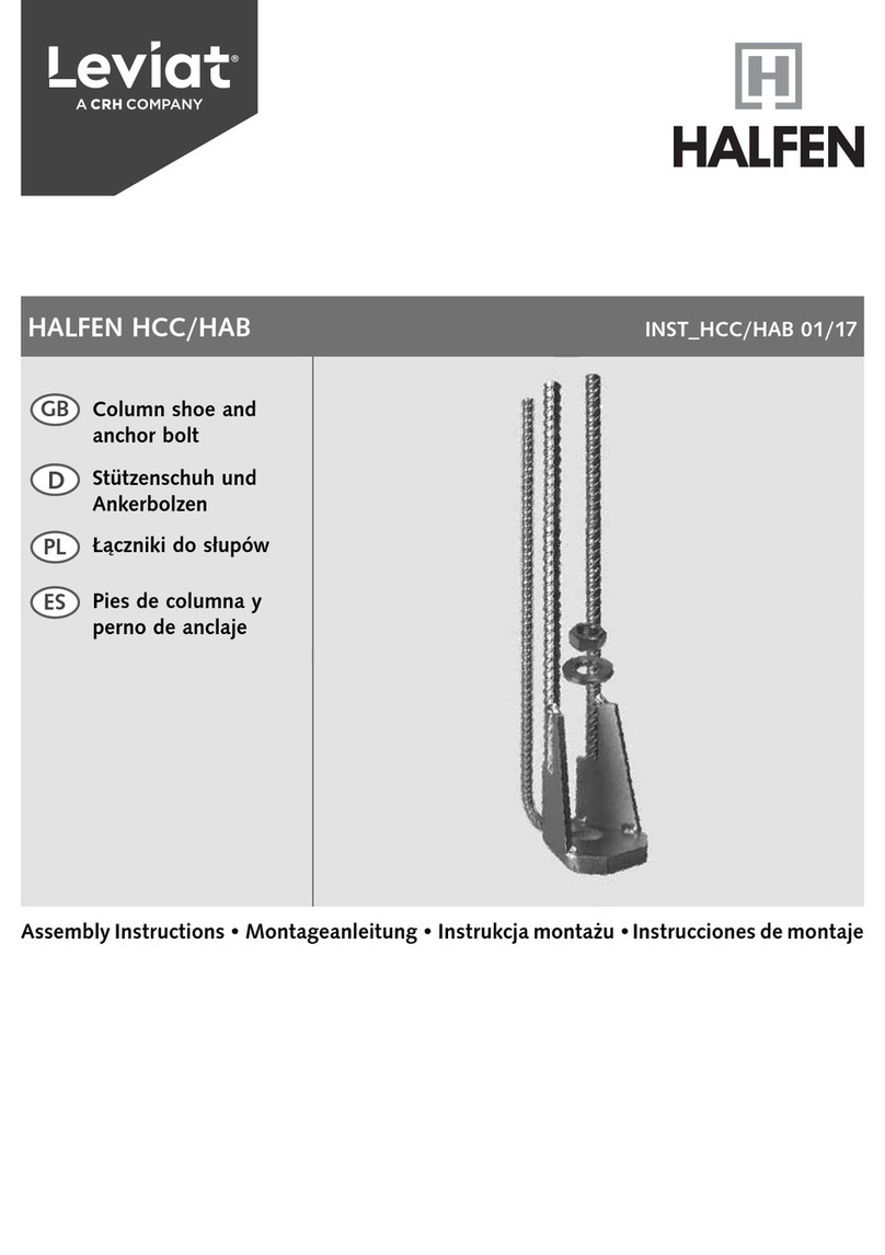
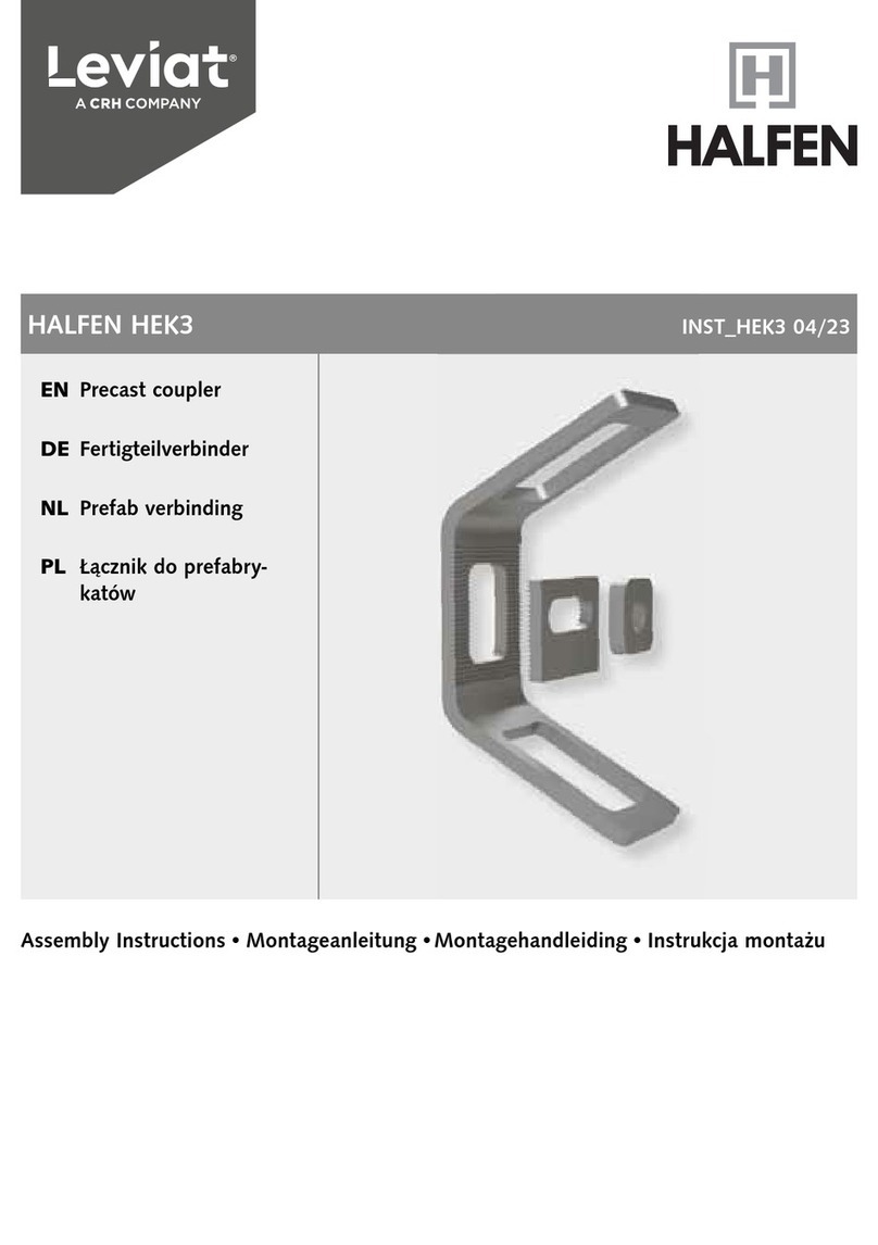
CRH Leviat HALFEN HEK3 User manual