ALUMAVENT 3100 Series User manual

222 Church St. Alliston, Ontario
Tel: (905) 857-4730 | 1-800-668-7214
Ventexinc.com 3100, 3900 series control dampers Pg. 1
Installation, Operation and Maintenance Manual
3100, 3900, Series Control Dampers
Safety Warning
Please read the installation, operation, and
maintenance instructions in whole preceding
to installing or servicing. Incorrect installation,
adjustment, change, service, or maintenance
can cause property damage, injury, or death.
Delivery and Handling
Once the dampers have been received, scan them for both visible and inconspicuous damage. If damage is
discovered, make a note of it on the bill of lading and proceed to file a claim with the transporter. Verify that
all elements of the package, including accessories, are accounted for and accurate.
Dampers need to be kept clean and dry at all times. It is highly advised that you store your items indoors and
protect them from dirt, dust, damage, and natural elements. It is advised to not store dampers in
temperatures above 100°F.

pg. 2
1) Review the schedules to see where the dampers should be installed in the building. Inspect the
damper for any signs of damage and dirt.
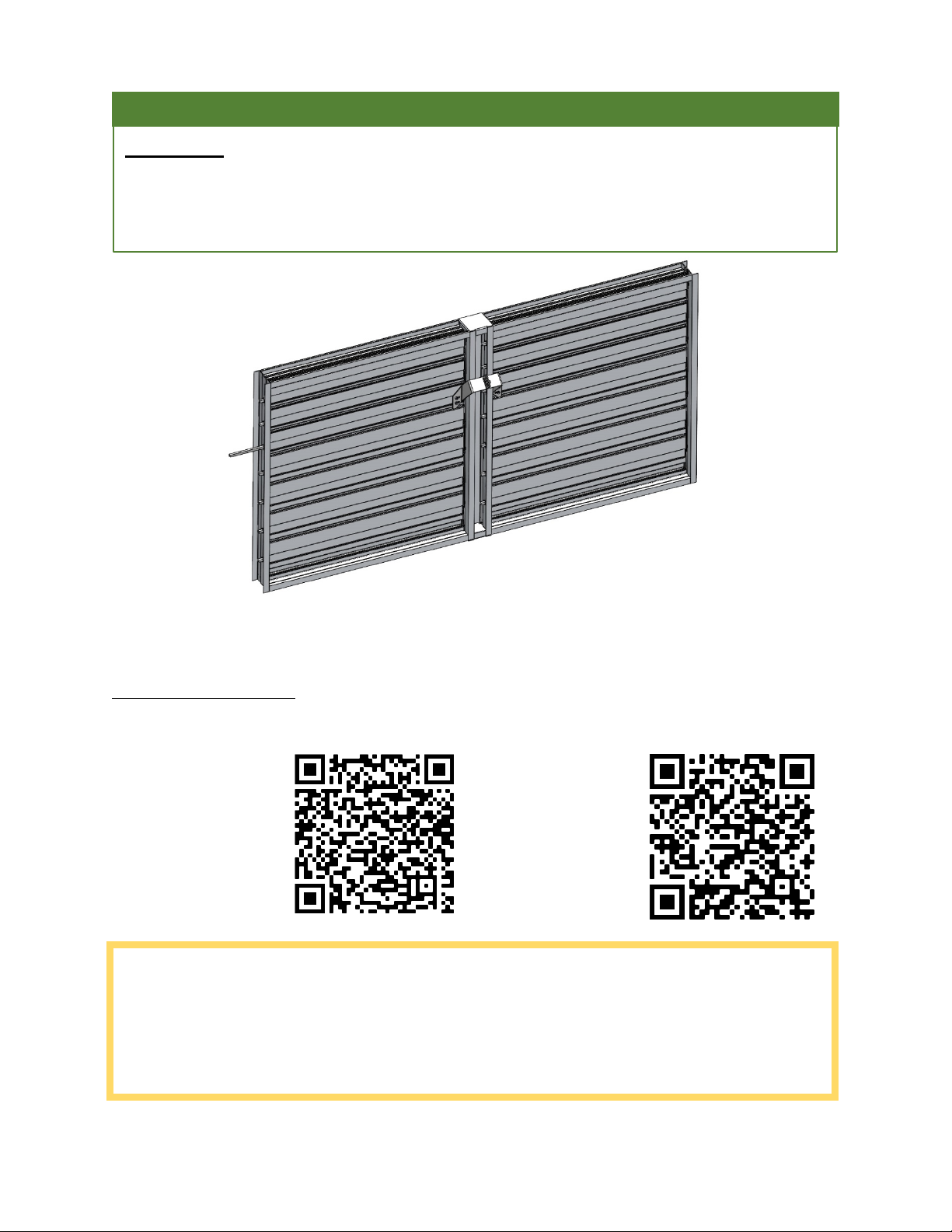
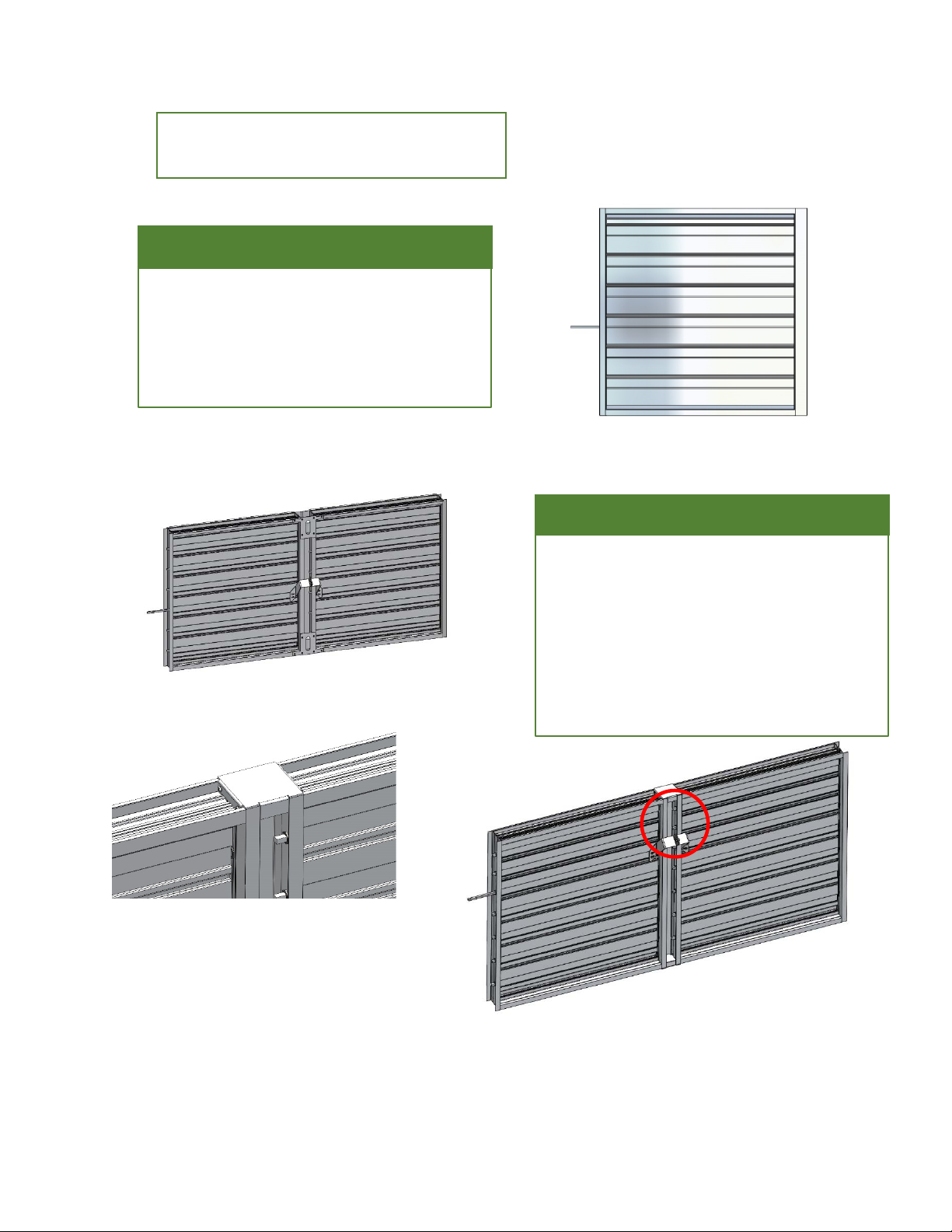
2) When moving the damper, only use the frame or sleeve. Do not use the blades, linkage, actuators,
or jackshafts to lift the damper as this could cause damage. Use enough support to raise each
section mullion uniformly when handling multi section dampers (see drawing). Avoid excessive
bending, twisting, or racking. The damper must not be dragged or stepped on.
3) Damper blades need to open and/or close properly. It is not recommended to install screws in the
damper frame that interfere with the blade linkage and prohibit this.
4) When putting dampers in ducts or apertures they need to be square and not have any twists.
Squeezing or stretching the damper into the duct or hole is NOT recommended. Dampers that
experience excessive leakage and/or torque needs that exceed damper/actuator design might result
from out of square, racked, twisted, or misaligned installations.
5) Before and after installation, the damper and actuator must be kept clean, dry, and free of debris,
dust, and other foreign materials. Metal shavings, sand, drywall dust, fireproofing materials, plaster,
and paint overspray are all examples of foreign materials.
6) If wall texturing or spray painting will be done within 10 feet (3 metres) of the damper, the damper
should be adequately covered to prevent overspray. Needless dirt and debris on the damper can
result in a higher chance of leakage and/or torque needs that are higher than the damper/actuator
design.
7) In order to maintain, inspect, and service the dampers, appropriate access to dampers and actuators
is needed. It will be required to install a removable section of duct if satisfactory size access cannot
be accomplished.
Electrical Guidelines:
All electrical and or pneumatic connections to damper actuators should be made in accordance with
applicable codes, ordinances and regulations according to region.
Pre-Installation Guidelines
The goal of a suitable installation is to attach the control damper into the opening in such a
way that damper action is not distorted or disrupted. The checklist below will help you
complete the damper installation in a timely and efficient manner.
Safety Danger
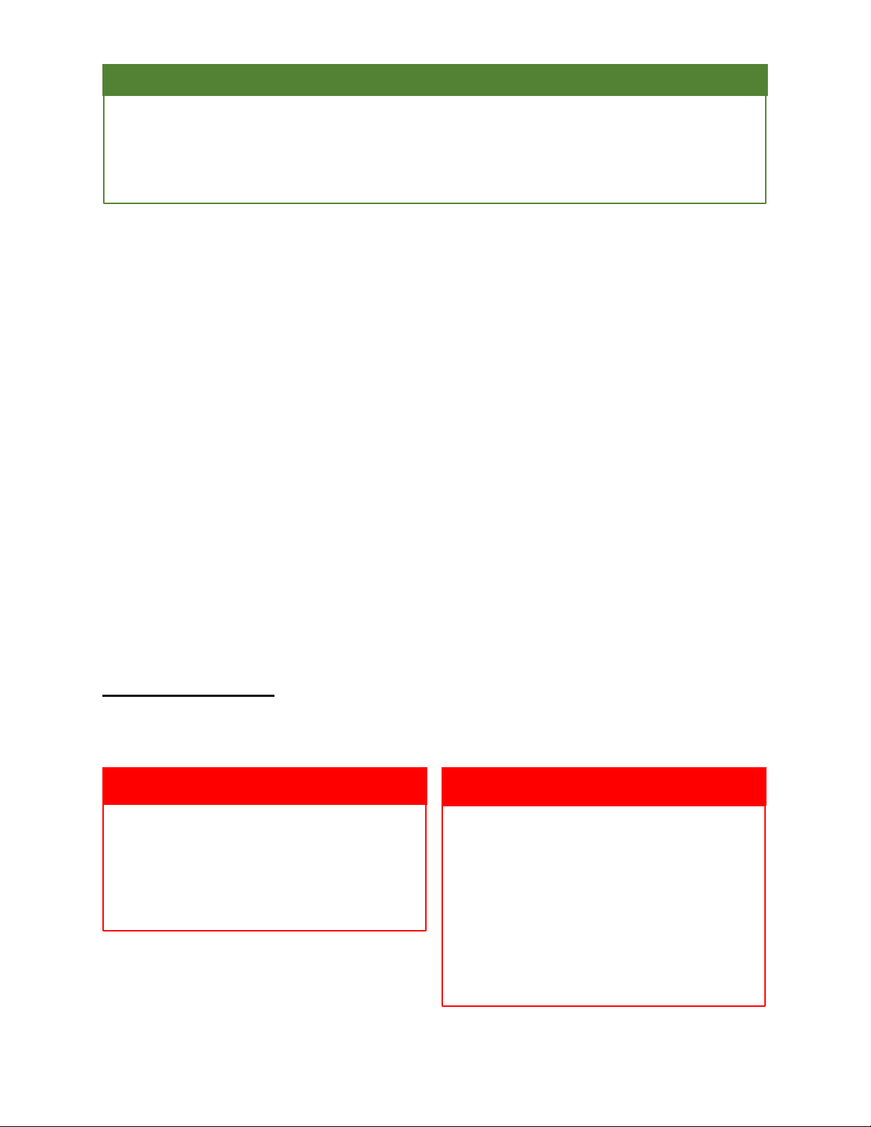
An electrical input may be needed for this
equipment. This work should be performed by
a qualified electrician only.
Safety Caution
Please verify power requirements before
wiring the actuator. Alumavent is not
responsible for any damage to, or failure of the
unit caused by incorrect field wiring. Electrical
and/or pneumatic connections to damper
actuators should be made in accordance with
wiring and piping diagrams developed in
compliance with applicable codes, ordinances
and regulations.

pg. 3
Installation Instructions
IMPORTANT: Failure to follow instructions will void all warranties.
IMPORTANT: MODEL SERIES’ 3100 AND 3900 DAMPERS WITH VISIBLE/EXPOSED SIDE BLADE
LINKAGE INSTALLED IN OR NEAR EXTERIOR WALLS MUST BE INSTALLED WITH EXPOSED
LINKAGE TOWARDS INTERIOR OF BUILDING.
3965 Series shown with jumper and mullion end caps installed
See Jackshaft
Instructions
See Jumper
Instructions
The number of sections in a damper assembly is not limited, however they must not exceed the
maximum section sizes listed below. Only the largest single piece of these dampers is designed to
be self-supporting. Bracing may be required for multiple section damper assemblies to sustain the
assembly's weight and keep it from collapsing under system pressure. To support the damper
horizontally, Alumavent suggests suitable bracing (installer is responsible for suitable bracing). To
avoid sagging due to damper weight, support ductwork in the area of the damper.

pg. 4
Damper Model Series – 3100 & 3900
Section Size – 48’’w x 60’’h (1219 x 1524)
Max. size for multi section dampers - unlimited
One Section Wide
Each damper section, including multi-section
assemblies are required to be square without
twisting, bending, or racking. Measure each
segment diagonally from the upper corners to
the opposite bottom corners.
Two Section Wide
Frame members are designed to overlay. The
offset overlaying frame comes with fasteners
installed. The installer may require bracing.
Ensure both sections are parallel, level, and
straight to each other. To add strength, add
multi-section brackets. Mullion end caps may
be used when linkages are to be clear of dirt
and debris
3961 Series
Series shown with mullion end caps. Follow multi section
brackets and end cap instructions.
3960 series shown with jumper and
multi section brackets installed.

pg. 5
3965 Series shown with jumper
(See jumper instructions QR code)
1) Shims shall be used between the damper frame and the duct aperture or opening gap to avoid the
frame from being distorted by the bolts that hold it in line. To reinforce for strength, brace every
horizontal mullion and every 8 feet of damper width vertically. High-velocity dampers (2000 fpm
[10.2 m/s]) could require further bracing. Alumavent dampers are built and engineered specifically
for structural integrity dependent on model and conditions. The installer is responsible for
attaching, framing, mating flanges, and anchoring damper assemblies into apertures, ducting, or
walls. Field engineers should determine the design calculations for these retaining and supporting
that particular installation.
2) The extension pin should extend roughly 4-6 inches (102-152mm) beyond the frame if the damper
actuator is to be installed out of the air stream. For jackshaft units, the jackshaft should extend
through the jackshaft bearing assembly and approximately 6 inches (152mm) beyond the frame for
jack shafted units.
3) Individual damper sections, as well as entire multi-section assemblies, need to be square and
without racking, twisting, or bending. Measure each portion diagonally from the upper corners to
the opposite bottom corners.
4) Damper blades, axles, and linkage must all function freely. Cycle dampers after installation to ensure
good operation before starting the system. All portions of a multi-section assembly should open and
close at the same time.
Multiple Section Wide
The bottom sections should be installed first. Set the second level of damper section(s) on top of the
bottom section(s), taking into consideration the alignment of all pieces. The installer may require
some bracing. It is important to ensuring both sections are straight, even, and parallel to each other.
To add strength, use multi-section brackets. Mullion end caps may be used when linkages are to be
kept free of dirt and debris (see two sections wide)

pg. 6
Operation:
Ensure that the blades open and close properly while running the damper through its full cycle. Check
for slack linkage, especially at the actuator, if there is a problem. Tighten the linkage as required.
Closure:
Remove any unnecessary objects that could hinder blade closure or appropriate blade-to-blade or
blade-to-frame seal.
Moving Parts:
Monitor those elements that are supposed to move freely, such as linkages, bearings, and blades, can.
Lubricating these components helps to keep them from rusting and accumulating unnecessary friction
over time. Only use Moli-spray oil or a related graphite-based dry lubricant since regular lubricating oil
attracts dirt more easily. When using ball bearings (without grease fittings) and synthetic, oil-
impregnated bearings lubrication is not necessary.
Foreign Matter:
Dirt and dirt can build up over time on damper surfaces. Wipe the damper surfaces with a non-oil-based
mild solvent/cleaner to avoid impeding airflow and buildup of debris.
Damper Trouble Shooting:
The following is a cause and correction list for common concerns regarding damper operation:
Symptom
Possible cause
Corrective Action
Damper fails to fully
open and/or fully
close
Frame is cracked/out of square
causing blades to bind on jamb seals
Adjust frame so that it is square and plumb
within the duct/opening
Linkage on actuator is loose
Close damper, disconnect power, adjust
and tighten linkage
Defective actuator
Replace actuator
Screws in damper linkage
Locate screws and remove or relocate
The linkage of the actuator is hitting
the wall or floor
Damper installed too far into wall. Move
out
Contaminants on damper
Clean with a non oil-based mild
solvent/cleaner
Actuator runs hot or
makes a humming
noise
Actuator prohibited from reaching
end of stroke
Disconnect linkage from
jackshaft, open damper, power actuator to
end of spring, tighten linkage. Verify
amperage draw
Warranty
Alumavent warrants this equipment to be free from defects in material and workmanship for a
period of one year from the purchase date. Any units or parts which prove to be defective during
the warranty period will be repaired or replaced at our option. Alumavent shall not be liable for
damages resulting from misapplication or misuse of its products. Alumavent will not be responsible
for any installation or removal costs. Alumavent will not be responsible for any service work or back
charges without prior written authorization.
This manual suits for next models
2
Table of contents
Popular Fire And Smoke Damper manuals by other brands

Advanced Air
Advanced Air 0160 Series quick start guide

Trox Technik
Trox Technik FKR-EU Supplementary Operating Manual

Trane
Trane BAYDMPR310 Series installation guide

System air
System air A-FDR-3G-OF instruction manual

Concept2
Concept2 Titanium TI100 Installation and operation manual

EWC Controls
EWC Controls PRD Technical bulletin

Lindab
Lindab WH45P Installation booklet

klimaoprema
klimaoprema FDSD product manual

Specified Technologies
Specified Technologies EZ PATH Installation sheet

Trane
Trane Precedent FIADMPR102 Series installation instructions

Advanced Air
Advanced Air 0160 Series Installation, operation and maintenance manual

Helios
Helios BRK Installation and operating instructions