Schako BSK-RPR Service manual

SCHAKO | Ferdinand Schad KG Phone +49 (0) 7463-980-0
Steigstraße 25-27 Fax +49 (0) 7463-980-200
Fig.: BSK-RPR with B10 drive
USABILITY CERTIFICATES
•Performance Reliability Certificate
according to EU-Bau PVO
0761 – CPR – 0245
•EC Certificate of Conformity
0761 – CPD – 0263
•Declaration of Performance
DoP-BSK-RPR-2017-08-09
CLASSIFICATION AND STANDARDS
•Classification
according to EN 13501-3, depending on the
mounting situation EI 90 (ve, hoi↔o) S
•Product standard
EN 15650
•Test standard
EN 1366-2
PERFORMANCE DATA
•For automatic locking of fire lobbies
•For use or connection of a smoke release device
with abZ (e.g. SCHAKO smoke detection system
RMS) in connection with suitable release de-
vices (e.g. spring return actuator)
SPECIAL FEATURES
•
ATEX
version available (at an extra charge)
•Extensive uses and applications
•Housing leakage class C according to EN 1751
•For optimum integration into the building con-
trol system via the SCHAKO EasyBus signalling
and switching bus system or the SCHAKO BKSYS
fire damper mini-controller
Technical documentation
Installation, mounting and operating instructions
BSK-RPR
Fire damper

Fire Damper Model BSK-RPR
Technical documentation
Table of Contents
Construction subject to change.
No return possible Version: 2017-08-09 | Page 2
TABLE OF CONTENTS
Table of Contents........................................................ 2
Description.................................................................. 3
Models and dimensions.............................................. 4
Installation details....................................................... 9
Installation in solid walls............................................. 9
Installation on solid walls with mounting frame AR . 10
Installation away from solid walls with mounting
frame AR ................................................................... 11
Installation in solid ceilings....................................... 12
Installation on solid ceilings with mounting frame AR
.................................................................................. 13
Installation with vertical concrete base on solid
ceilings ...................................................................... 14
Installation in lightweight partition walls with metal
posts and panelling on both sides ............................ 15
Installation in lightweight partition walls with metal
posts and panelling on both sides near the ceiling
(solid ceiling)............................................................. 16
Installation with mounting AR in lightweight partition
walls with metal posts and panelling on both sides . 17
Installation close to ceiling (solid ceiling) ................. 18
Installation kit GDL for installation in lightweight
partition walls with metal posts and panelling on both
sides with sliding ceiling connection......................... 20
Installation in lightweight partition walls with metal
posts and panelling on both sides (F30) ................... 22
Installation close to ceiling (solid ceiling) ................. 23
Installation with mounting AR in lightweight partition
walls with metal posts and panelling on both sides
(F30).......................................................................... 24
Installation close to ceiling (solid ceiling) ................. 26
Installation in shaft walls with metal post and
panelling on one side................................................ 27
Installation close to ceiling (solid ceiling) ................. 28
Installation in shaft walls with metal post and
panelling on one side with mounting frame AR ....... 29
Installation close to ceiling (solid ceiling) ................. 30
Installation information ............................................ 31
Technical data........................................................... 34
Accessories ............................................................... 37
Limit switch............................................................... 37
Spring return actuators............................................. 38
Magnets.................................................................... 43
Add-on parts ............................................................. 44
CE marking ................................................................ 47
Order code................................................................ 48
Specification texts..................................................... 50
Service....................................................................... 53
Foreign branch offices .............................................. 58
List of figures/tables/diagrams................................. 59

Fire Damper Model BSK-RPR
Technical documentation
Description
Construction subject to change.
No return possible Version: 2017-08-09 | Page 3
DESCRIPTION
Fire dampers, installed in ventilation ducts (air conditioning
systems), serve for the automatic locking of fire lobbies.
The fire damper BSK-RPR corresponds to EN 15650, EN 13501-
3 and EN 1366-2.
The BSK-RPR has been tested according to EN 1366-2 in compli-
ance with Declaration of Performance no. DoP-BSK-RPR-2017-
08-09. It has the Performance Reliability Certificate according to
EU-Bau PVO 0761-CPR-0245 and the EC Certificate of Conformity
0761-CPD-0263. Its category according to EN 13501-3 is EI 90 (ve,
hoi ↔ o) S.
According to Directive 2014/34/EU, EC Certificate of Conform-
ity Number EPS 09 ATEX 2 153 X, its use in areas subject to
explosion hazards is permitted, not only with spring return ac-
tuator X10 (ExMax-5.10-BF), including safety temperature lim-
iter (FireSafe or ExPro-TT), but also with mechanical trigger via
fusible link (manual actuation with or without ATEX limit
switch ES-Ex). The fire damper is marked as follows according
to ATEX:
II 2 G IIC T6
II 2D T80°C
II 3 D T80°C*)
EPS 09 ATEX 2 153 X
*)when using the safety temperature limiter FireSafe.
The national standards and guidelines must be observed in
connection with this technical documentation, installation,
mounting and operating instructions. Further information on
ATEX can be found in the additional operating instructions
BSK-RPR according to ATEX 2014/34/EU (document: Z09/46).
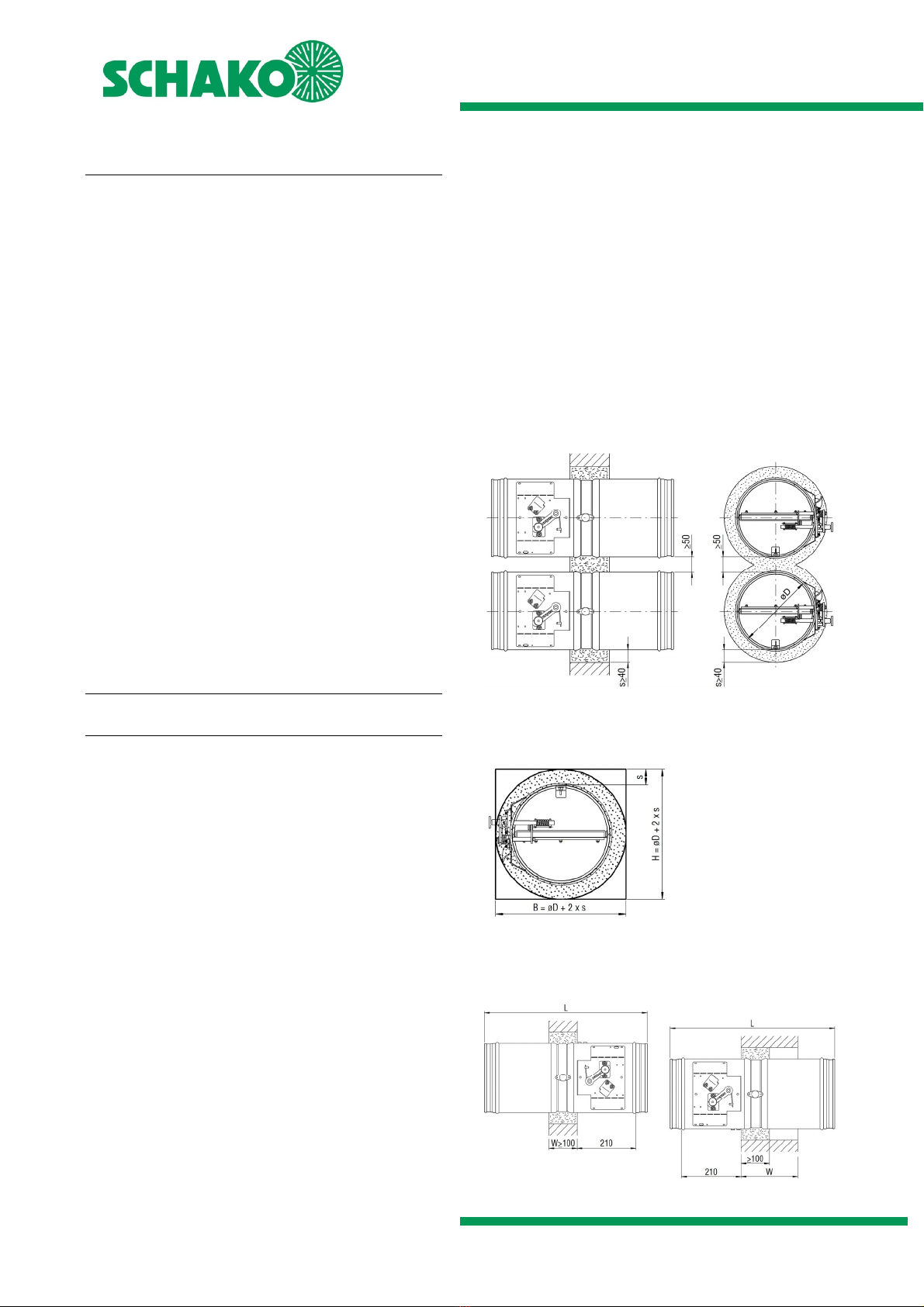
For service, retrofitting, etc., inspection openings must be pro-
vided on site in suspended ceilings, shaft walls, connected ven-
tilation ducts etc., if necessary. They must be built in in suffi-
cient numbers and sizes and must not impair the functioning
of the fire dampers.
The fire dampers must be connected to the ventilation system
by means of ventilation ducts either on one or on both sides.
When connected on one side, security grilles made of non-
flammable building materials (EN13501-1) must be provided
on opposite sides.
The fire dampers can be connected to non-flammable or to
flammable ventilation ducts.
Housing made of galvanised sheet steel (standard), option-
ally (at an extra charge):
Housing made of stainless steel material no. 1.4301
or material no. 1.4571
Housing with DD coating (two-component top coat
based on polyurethane varnish) inside / outside
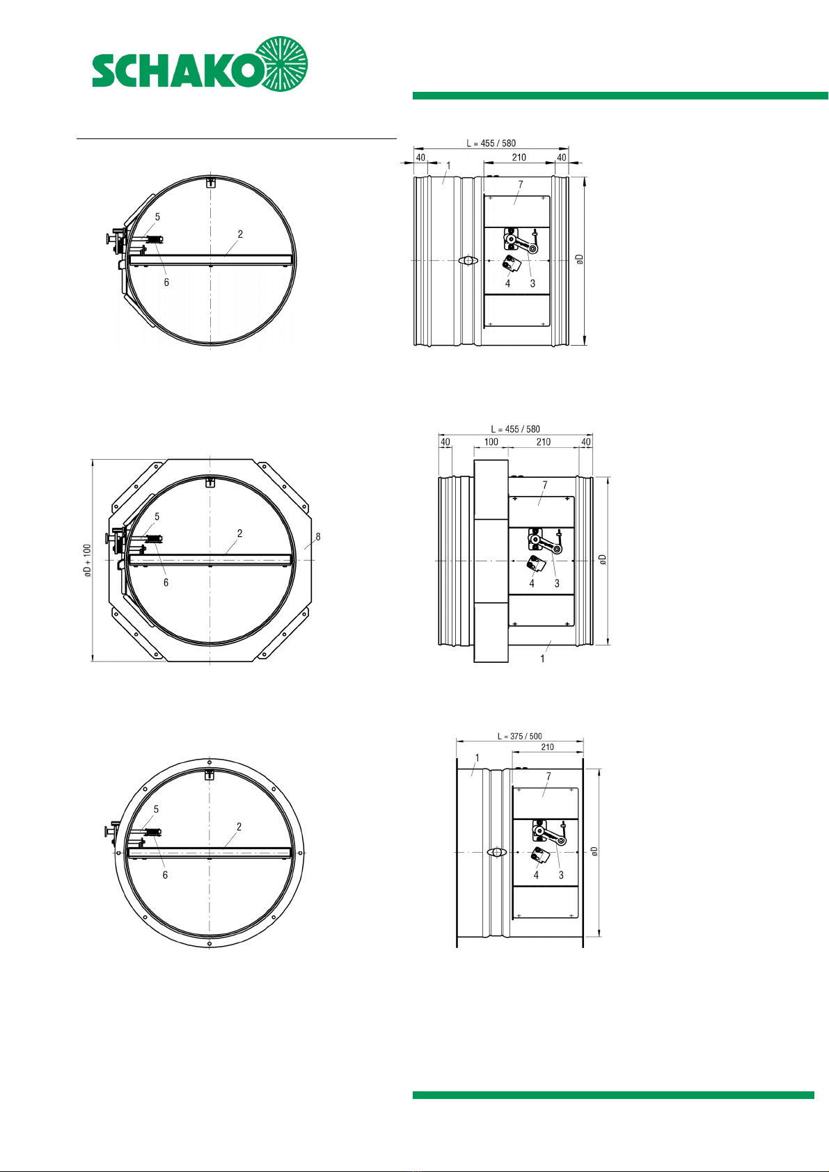
Model with plug-in connection (-S) or flanged connection
(-F) according to EN 12220 and DIN 24154-1, respectively.
Damper leaf made of silicate board,
optionally (at an extra charge):
DD coating (RAL 7035 / light-grey)
Cold and hot leakage requirements according to EN 1366-
2 are complied with using circumferential rubber and intu-
mescent seals.
Horizontal or vertical position of the damper leaf axle pos-
sible.
The installation position is independent of the air flow di-
rection.
Thermal release via fusible link 72°C or 98°C;
optionally (at an extra charge)
equipped with electrical or magnetic release de-
vices
Use: max. operating pressure of 1000 Pa at vface ≤10 m/s
Housing leakage class C according to EN 1751
Use or connection of a smoke release device with general
building supervisory approval (e.g. SCHAKO smoke detec-
tion system RMS, see technical documentation smoke de-
tection system RMS) in connection with suitable electric,
magnetic (magnetic clamp) release devices of the fire
damper is possible; only release devices working by the
"currentless closed" principle may be connected to the
RMS system; the propagation of fire and smoke is effec-
tively prevented. Optimal integration into the building
control system by means of the SCHAKO EasyBus signalling
and switching bus system (see technical documentation
EasyBus) or the SCHAKO fire damper mini-controller BKSYS
(see technical documentation BKSYS).
MAINTENANCE INFORMATION
We would like to point out that only suitable cleaning materi-
als may be used to clean the stainless steel version of fire
dampers!
ATTENTION
Building systems have to be arranged, installed and main-
tained in such a way that they prevent fire and propagation of
fire and smoke (fire propagation) and allow evacuation of per-
sons and animals as well as efficient fire extinguishing work in
case of fire. A propagation of smoke through the ventilation
and air-conditioning systems can effectively only be prevented
by means of suitable electric or magnetic (magnetic clamp) re-
lease devices in connection with a smoke detection system.
We therefore recommend fitting the fire dampers, for exam-
ple, with electric spring return actuators that can be triggered
by the smoke detector.

Fire Damper Model BSK-RPR
Technical documentation
Models and dimensions
Construction subject to change.
No return possible Version: 2017-08-09 | Page 4
MODELS AND DIMENSIONS
BSK-RPR – Nominal sizes 100 to ≤250
BSK-RPR-S (plug-in connection)
Fig. 1: Dimension BSK-RPR-S – Nominal sizes 100 to ≤250
BSK-RPR-S with mounting frame AR
(Mounting frame AR only possible in -S design, pre-mounted
ex works, delivery in loose form not possible)
Fig. 2: Dimension BSK-RPR-S with mounting frame AR –
Nominal sizes 100 to ≤250
BSK-RPR-F (flanged connection)
Fig. 3: Dimension BSK-RPR-F – Nominal sizes 100 to ≤250
1 Housing 5 Trigger device
2 Damper leaf 6 Fusible link
3 Hand lever 7 Actuator unit
4 Locking profile 8 Mounting frame AR

Fire Damper Model BSK-RPR
Technical documentation
Models and dimensions
Construction subject to change.
No return possible Version: 2017-08-09 | Page 5
BSK-RPR – Nominal sizes > 250 to 500
BSK-RPR-S (plug-in connection)
Fig. 4: Dimension BSK-RPR-S – Nominal sizes >250 to 500
BSK-RPR-S with mounting frame AR
(Mounting frame AR only possible in -S design, pre-
mounted ex works, delivery in loose form not possible)
Fig. 5: Dimension BSK-RPR-S with AR – Nominal sizes > 250
to 500
BSK-RPR-F (flanged connection)
Fig. 6: Dimension BSK-RPR-F – Nominal sizes > 250 to 500
1 Housing 5 Trigger device
2 Damper leaf 6 Fusible link
3 Hand lever 7 Actuator unit
4 Locking profile 8 Mounting frame AR

Fire Damper Model BSK-RPR
Technical documentation
Models and dimensions
Construction subject to change.
No return possible Version: 2017-08-09 | Page 6
Available sizes
No-
mi-
nal
size
øD
[mm]
L [mm]
BSK-RPR-S BSK-RPR-F
100 98
125 123
140 138
160 158
180 178 455 375
200 198
224 222
250 248
280 278 580 500
315 313 (standard) (standard)
355 353
400 398
450 448
500 498
Table 1: Available sizes
Rubber lip seal for BSK-RPR-S
Model BSK-RPR-S is delivered as standard with a rubber lip
seal.
Fig. 7: Rubber lip seal
Release devices (pos. 5)
Fig. 8: Release device BSK-RPR
Flange bores BSK-RPR-F
Fig. 9: Flange bores
Table to DIN EN 12220 or DIN 24154-1
Nomi-
nal
size
øD
[mm]
øC
[mm]
Bolt circle
øB
Number of
bores
(± 0.5mm) Ø9.5 (± 0.5mm)
100 98 150 132 4
125 123 175 157 4
140 138 190 172 6
160 158 210 192 6
180 178 230 212 6
200 198 250 233 6
224 222 274 257 6
250 248 300 283 6
280 278 340 317 8
315 313 375 352 8
355 353 415 392 8
400 398 460 438 8
450 448 510 488 8
500 498 560 538 8
Table 2: Flange bores
SCHAKO ASG-RF / VT-RF / FS-RF: Flange bores suitable for
BSK-RPR-F

Fire Damper Model BSK-RPR
Technical documentation
Models and dimensions
Construction subject to change.
No return possible Version: 2017-08-09 | Page 7
Damper leaf projecting ends
BSK-RPR-S
Fig. 10: Damper leaf projecting ends BSK-RPR-S
No-
minal
size
øD
Operating
side
(BS)
Non-operating side
(NBS)
L=455 / 580 L=455 L=580
100 98 256
x
107
Y
232
y
125 123 244 95 220
140 138 236 87 212
160 158 226 77 202
180 178 216 67 192
200 198 206 57 182
224 222 194 45 * 170
250 248 181 32 * 157
280 278 166 17 * 142
315 313 149 0 * 125
355 353 129 20 *
Y1
105
400 398 106 43 * 82
450 448 81 68 * 57
500 498 56 93 * 32 *
* Extension piece (on site) necessary
Table 3: Damper leaf projecting ends BSK-RPR-S
"a"= 50
mm:
Minimum distance between the front edge
of the open damper leaf and the security
grille (ASG) or flexible connection piece (FS).
BSK-RPR-F
Fig. 11: Damper leaf projecting ends BSK-RPR-F
No-
minal
size
øD
Operating
side
(BS)
Non-operating side
(NBS)
L=375 / 500 L=375 L=500
100 98 216
x
67
Y
192
y
125 123 204 55 180
140 138 196 47 * 172
160 158 186 37 * 162
180 178 176 27 * 152
200 198 166 17 * 142
224 222 154 5 * 130
250 248 141 8 *
Y1
117
280 278 126 23 * 102
315 313 109 40 * 85
355 353 89 60 * 65
400 398 66 83 * 42 *
450 448 41 * 108 *17 *
500 498 16 * 133 *8 * Y1
* Extension piece (VT-RF) necessary
Table 4: Damper leaf projecting ends BSK-RPR-F

Fire Damper Model BSK-RPR
Technical documentation
Models and dimensions
Construction subject to change.
No return possible Version: 2017-08-09 | Page 8
Use
The fire damper type BSK-RPR can be fitted as shown in the
following table.
Table 5: Usability
Use Installa-
tion
BSK-RPR
Nominal
size
from to
Material/Model
Mini-
mum
thickness
[mm]
Minimum
distance of
two
BSK-RPR
from one
another
[mm]
Fire resistance
class
Notes
Page °
WALL
solid
Apparent
density
≥450kg/m³
in 100 – 500
for example, concrete, masonry according
to EN 1996 or DIN 1053; solid plaster wall
boards according to EN 12859 or DIN 18163
100 50
EI 90 (ve, i↔o) S 9
on5) 100 – 500
for example, concrete, masonry according
to EN 1996 or DIN 1053; solid plaster wall
boards according to EN 12859 or DIN 18163
100 2003) EI 90 (ve, i↔o) S 10
away
from 1) 100 – 500
for example, concrete, masonry according
to EN 1996 or DIN 1053; solid plaster wall
boards according to EN 12859 or DIN 18163
100 2004) EI 90 (ve, i↔o) S 11
Lightweight
partition
wall
in
100 –500
in lightweight partition walls with metal
posts and panelling on both sides according
to classification to EN 13501-2 or compara-
ble national standards.
100 50
EI 90 (ve, i↔o) S 15
100 – 250
in lightweight partition walls with metal
posts and panelling on both sides according
to classification to EN 13501-2 or compara-
ble national standards.
75 200
EI 30 (ve, i↔o) S 22
in lightweight partition walls with metal
posts and panelling on one side according to
classification to EN 13501-2 or comparable
national standards
125 200
EI 90 (ve, i↔o) S 27
on5) 100 – 500
with mounting frame AR on lightweight par-
tition walls with metal posts and panelling
on both sides according to classification to
EN 13501-2 or comparable national stand-
ards
100 200
EI 90 (ve, i↔o) S 15
with mounting frame AR on lightweight par-
tition walls with metal posts and panelling
on both sides according to classification to
EN 13501-2 or comparable national stand-
ards, in the area of sliding ceiling connec-
tions 2)
100 170
EI 90 (ve, i↔o) S 20
with mounting frame AR on lightweight par-
tition walls with metal posts and panelling
on both sides according to classification to
EN 13501-2 or comparable national stand-
ards
75 200
EI 30 (ve, i↔o) S 24
with mounting frame AR on lightweight par-
tition walls with metal posts and panelling
on one side according to classification to EN
13501-2 or comparable national standards
125 200
EI 90 (ve, i↔o) S 29
CEILIN
G
solid
Apparent
density
≥500kg/m³
in 100 – 500
for example, concrete, aerated concrete
125 55
EI 90 (ho, i↔o) S 12
on5) 100 – 500 for example, concrete, aerated concrete 125 200 EI 90 (ho, i↔o) S 13
on 6) 100 - 500 for example, concrete, aerated concrete 125 55 EI 90 (ho, i↔o) S 14
The BSK-RPR may also be installed in walls or ceilings of lower fire resistance class. In this case, the BSK-RPR has the same fire
resistance class as the wall or ceiling.
1) Installation only in connection with a ventilation duct devoid of openings (fire resistance duration 90 min.) between the BSK-RPR and the fire-
resistant wall to be protected. Mounting only allowed in conjunction with mounting frame AR.
2) The exact wall thickness/es must be taken into account and specified when ordering. For installation, the accessories for sliding ceiling con-
nection plus mounting frame AR are required.
3) At nominal sizes of 100 - 250, mounting is allowed at a reduced distance (mounting frame AR to mounting frame AR).
4) The allowed minimum distance of the fire dampers to one another is at least 200 mm. However, due to the construction, the distance must
be selected as a function of the particular design of the panelling.
5) Mounting only allowed in conjunction with mounting frame AR.
6) Installation only in connection with a concrete base still to be made on site.

Fire Damper Model BSK-RPR
Technical documentation
Installation details
Construction subject to change.
No return possible Version: 2017-08-09 | Page 9
General information
During mounting or installation, there is a risk of injuries.
To avoid any possible injuries, personal protective equip-
ment (PPE) must be worn.
Fire dampers must be installed such that external forces
do not impair their permanent functioning. During mount-
ing it may be required to provide reinforcements for the
housing or the like. The requirement of statically load-
bearing lintels may have to be taken into consideration.
Improper transport/handling may result in damage/func-
tional impairment. In addition to that, the film of the
transport packaging must be removed and the delivery in-
spected for completeness.
In storage, fire dampers must be protected from dust, dirt,
moisture and the effects of temperature (e.g. direct sun-
light, heat-emitting light source, etc.). They must not be
exposed to direct effects of the weather and must not be
stored below -40 °C or above 50 °C.
The fire damper must be protected from dirt and damage.
After installation is complete, any dirt must be removed
immediately.
Enough space must be provided for installation, mortar lin-
ing, etc.
Carry out a functional check of the fire damper before and
after mounting and ensure ready access.
Electrical installations or work on electrical components
may only be carried out by skilled electricians. The supply
voltage must be switched off when performing this work
and secured against being switched on again.
INSTALLATION DETAILS
Installation in solid walls
Nominal sizes 100 to 500 – (wet installation)
Installation in solid walls (shaft walls, shafts, ducts and fire
walls) made of, for example, concrete, masonry according
to EN 1996 or DIN 1053; solid plaster wall boards according
to EN 12859 or DIN 18163; apparent density ≥450 kg/m³
and wall thickness W ≥100 mm.
Circumferential gaps "s" must be completely filled with
mortar of category M15 according to EN 998-2, NM III DIN
V 18580 (previously: MG III according to DIN 1053) or fire
protection mortar of suitable grades. The minimum gap
size smin is 40 mm. The filling with mortar must be executed
such that it is permanent. The information given by the
mortar manufacturer must be observed. If the fire damper
is installed during the construction of the wall, the gaps "s"
can be omitted. The mortar bed depth must be designed
according to the minimum wall thickness and may not be
less than this thickness. When performing a mortar lining
or direct installation, make sure that the housing is not
pressed toward the inside (reinforcement). If necessary, a
statically active lintel must be provided (e.g. with flexible
ceiling connection).
The distance of the fire dampers to one another (no more
than 2) must be at least 50 mm.
The distance to load-bearing, adjacent components (wall
/ solid ceiling) is at least 40 mm.
Installation at a reduced distance
Installation of the fire dampers in an existing wall recess or a
wall recess still to be constructed. It must be made such that
the minimum gap size smin between housing and solid ceiling is
40 mm. The gaps "s" and the void between the fire dampers
must be completely filled with mortar of category M15 to EN
998-2, NM III DIN V 18580 (previously: MG III to DIN 1053) or
fire protection mortar of suitable grades in the minimum wall
thickness. If during the construction of the solid ceiling, the fire
dampers are installed, the gaps "s" can be omitted, but the
cavity between the fire dampers must always be filled as de-
scribed above.
Fig. 12: Wet installation, reduced distance in solid walls
(round recess, as drawn or rectangular)
Minimum gap size with complete mortar lining
Fig. 13: Minimum gap size complete mortar lining, solid walls
(round recess, as drawn or rectangular)
Installation positions
Mortar lining entire wall thickness mortar lining in minimum wall thick-
ness
Fig. 14: Wet installation in solid walls

Fire Damper Model BSK-RPR
Technical documentation
Installation details
Construction subject to change.
No return possible Version: 2017-08-09 | Page 10
Installation on solid walls with mounting frame AR
Nominal sizes 100 to 500 - (dry installation)
Installation on solid walls (shaft walls, shafts, ducts and fire
walls) made of, for example, concrete, masonry according
to EN 1996 or DIN 1053; solid plaster wall boards according
to EN 12859 or DIN 18163; apparent density ≥450 kg/m³
and wall thickness W ≥100 mm only in conjunction with
mounting frame AR.
The distance of the fire dampers to one another must be
at least 200 mm. (For nominal sizes 100 - 250, mounting is
allowed at a reduced distance - mounting frame AR to
mounting frame AR of no more than 2 BSK-RPR).
The distance to load-bearing, adjacent components (wall /
solid ceiling) is at least 75 mm.
The installation opening of size øD+10 mm is produced us-
ing a core hole bore.
For fastening to massive walls, only approved fastening
materials (dowels, etc.) must be used. Fastening is effected
on all 4 existing fixing lugs (For nominal sizes 100 - 160 all
existing and for nominal sizes 180 - 500 the two outer
bores of each fixing lug must be used).
Fig. 15: Dry installation on solid walls
Abb. 16: Detail showing fastening to solid walls
Installation without clearance (mounting frame AR to mount-
ing frame AR)
Nominal sizes 100 to ≥250 - (dry installation)
For nominal sizes 100 to ≤250, mounting at a reduced dis-
tance -mounting frame AR to mounting frame AR
of no
more than 2 BSK-RPR
- is allowed.
Fig. 17: Dry installation on solid walls, BSK-RPR nominal size
≤250 - minimum distance from one another
Nominal sizes > 250 to 500 - (dry installation)
For nominal sizes > 250, the distance of fire dampers from
one another must be at least 200 mm.
Fig. 18: Dry installation on solid walls, BSK-RPR nominal size
> 250 - minimum distance from one another
Fixing lug
Fastening material accord-
ing to statics and on-site
fire protection certificate
Fixing lug
Detail A (drawn rotated by 90°)
A

Fire Damper Model BSK-RPR
Technical documentation
Installation details
Construction subject to change.
No return possible Version: 2017-08-09 | Page 11
Installation away from solid walls with mounting
frame AR
Nominal sizes 100 to 500 - (dry installation)
Installation away from solid walls (shaft walls, shafts, ducts
and fire walls) made of, for example, concrete, masonry
according to EN 1996 or DIN 1053; solid plaster wall boards
according to EN 12859 or DIN 18163; apparent density ≥
450 kg/m³ and wall thickness W ≥100 mm only in conjunc-
tion with mounting frame AR.
When fitting the fire damper away from solid walls, it must
be suspended from the ceiling.
Installation only in connection with a ventilation duct de-
void of openings (fire resistance duration 90 min.), made
of sheet steel with external insulation made of board ma-
terial.
The connection of the fire-resistant ventilation duct (with
proven fire resistance duration of 90 minutes) between
the fire damper and the fire-resistant wall to the protected
must be effected by form-fit, but not by force-fit, in the
area of the wall opening.
The duct must be connected to the side of the BSK-RPR op-
posite to the fire-resistant duct (operating side) by means
of a flexible connection piece (alternatively: flexible venti-
lation duct made of aluminium or in special cases made of
steel).
A distance of the fire dampers from one another of at least
200 mm must be observed. However, due to the construc-
tion, the distance must be selected as a function of the par-
ticular design of the panelling.
The same also applies to the distance from load-carrying,
adjacent components (wall / solid ceiling).
1) Fire damper model BSK-RPR with mounting frame AR
2) Fire-resistant ventilation duct (with proven fire resistance
duration of 90 minutes)
3) Promatect-LS support 60 mm wide 200 mm long, adjust
thickness to the selected fire-resistant duct
4) Promatect-LS faceplate 35 mm (opening centrally in face-
plate = BSK-RPR øD +10 mm)
5) Countersunk head screw 4.5x35 or 5.0x30 or equivalent
with U-washer. Fastening is effected on all 4 existing fix-
ing lugs (For nominal sizes 100 - 160 all existing and for
nominal sizes 180 - 500 the two outer bores of each fixing
lug must be used).
6) Drywall screws 4.0x60, distance from the edge approx. 80
mm, screw distances a ≤180 mm or at least 2 screws per
side
7) Hilti MQ 41/3 or equivalent or U-profile 50 to DIN 1026
8) Fastening by means of fasteners with proven fire protec-
tion
9) The suspensions have to be executed with sufficiently di-
mensioned threaded rods. For information on the sus-
pension, see page 33.
10) Solid ceiling
FS Flexible spigot type FS-RS (normally inflammable to EN
13501-1)
Wall connections as specified by duct manufacturer. form-fit,
but not force-fit
Fig. 19: Installation away from solid walls
Installation procedure
Attach fire protection insulation made of board material
(pos. 2), to the existing ventilation duct, according to spec-
ifications of the duct manufacturer. A Promatect-LS sup-
port (pos. 4) must be provided on the non-operating side.
Attach a faceplate (pos. 4) with central installation ope-
ning.
Suspensions and fastenings (pos. 3/6/7) of the ducts and
of the insulation made of board material must be executed
with sufficiently dimensioned threaded rods according to
the duct manufacturer.
Mount the BSK-RPR (pos.1) on the existing ventilation duct
made of sheet steel, if necessary, with the additional use
of mounting suspensions, etc.
Mount the ventilation duct on the operating side using a
flexible connection piece.
Remove mounting aids (mounting suspensions etc.)

Fire Damper Model BSK-RPR
Technical documentation
Installation details
Construction subject to change.
No return possible Version: 2017-08-09 | Page 12
Installation in solid ceilings
Nominal sizes 100 to 500 – (wet installation)
Installation in solid ceilings made, for example, of con-
crete, aerated concrete, apparent density ≥500 kg/m³ and
ceiling thickness D ≥125 mm.
Installation with complete mortar lining (the circumferen-
tial gaps "s" must be completely filled with mortar of cate-
gory M15 to EN 998-2, NM III DIN V 18580 (previously: MG
III to DIN 1053) or fire protection mortar of suitable grades.
The minimum gap size smin is 40 mm. The filling with mortar
must be executed such that it is permanent. The infor-
mation given by the mortar manufacturer must be ob-
served. If the fire damper is installed during the construc-
tion of the ceiling, the gaps "s" can be omitted. The mortar
bed depth must not be less than 125 mm. When perform-
ing a mortar lining or direct installation, make sure that the
housing is not pressed toward the inside (reinforcement).
The distance of the fire dampers to one another (no more
than 2) must be at least 55 mm.
The distance to load-bearing, adjacent components (wall)
is at least 40 mm.
Installation at a reduced distance
Installation of the fire dampers in an existing ceiling recess or
a ceiling recess still to be made. It must be made such that the
minimum gap size smin between housing and solid ceiling is 40
mm. The gaps "s" and the void between the fire dampers must
be completely filled with mortar of category M15 to EN 998-2,
NM III DIN V 18580 (previously: MG III to DIN 1053) or fire pro-
tection mortar of suitable grades in the minimum ceiling thick-
ness. If during the construction of the solid ceiling, the fire
dampers are installed, the gaps "s" can be omitted, but the
cavity between the fire dampers must always be filled as de-
scribed above.
Fig. 20: Wet installation at a reduced distance, solid ceilings
(round recess as drawn or rectangular)
Minimum gap size with complete mortar lining
Fig. 21: Minimum gap size complete mortar lining, solid ceil-
ings (round recess as drawn or rectangular)
Installation positions
vertical suspended
For large ceiling thicknesses
vertical suspended
Fig. 22: Installation in solid ceilings - (wet installation)

Fire Damper Model BSK-RPR
Technical documentation
Installation details
Construction subject to change.
No return possible Version: 2017-08-09 | Page 13
Installation on solid ceilings with mounting frame AR
Nominal sizes 100 to 500 - (dry installation)
Installation on (directly on/directly under) solid ceilings
made, for example, of concrete, aerated concrete, appar-
ent density ≥500 kg/m³ and ceiling thickness D ≥125 mm,
only in connection with a mounting frame AR.
The distance between the fire dampers must be min. 200
mm.
The distance to load-bearing, adjacent components (wall)
is at least 75 mm.
The installation opening of size øD+10 mm is produced us-
ing a core hole bore.
For fastening to solid ceilings, only approved fastening ma-
terials (dowels, etc.) must be used. Fastening is effected on
all 4 existing fixing lugs (For nominal sizes 100 - 150 the
central bore or one bore of each fixing lug must be used).
vertical
suspended
Fig. 23: Installation positions on solid ceilings - (dry installa-
tion)
Abb. 24: Detail showing fastening to solid ceilings
Fastening material accord-
ing to statics and on-site
fire protection certificate
Fixing lug
Detail A (drawn rotated by 90°)
Fixing lug
A

Fire Damper Model BSK-RPR
Technical documentation
Installation details
Construction subject to change.
No return possible Version: 2017-08-09 | Page 14
Installation with vertical concrete base on solid ceil-
ings
Nominal sizes 100 to 500 – (wet installation)
Vertical installation on solid ceilings made, for example, of
concrete, aerated concrete, apparent density ≥500 kg/m³
and ceiling thickness
D ≥125 mm.
•Construction of a circumferential, straight reinforced con-
crete base (concrete grade: C20/25; concrete cover ≥35
mm; reinforcement: concrete steel BSt500S concrete steel
mats B500A).
The base must be constructed circumferentially with a wall
thickness of at least 100 mm, measured from the housing
of the fire damper. The height of the base must be main-
tained up to the prescribed installation dimension (210
mm). The maximum base height is ≤550 mm.
The damper leaf clearance of the installed fire damper
must be guaranteed. Make sure that there is nothing left
that may affect the function of the new fire damper.
Prior to installation of the fire damper, fastening materials
(e.g. screws, press-in nuts, etc.) must be provided and at-
tached on the non-operating side for mounting duct com-
ponents or, if subsequent mounting is no longer possible,
the ventilation duct must be connected prior to installa-
tion. Alternatively, extension pieces (on site or as accesso-
ries, e.g. SCHAKO type VT-RF for BSK-RPR) can be
mounted.
During the formation of the concrete base on solid ceilings,
in addition to the constructive crack reinforcement, it must
be ensured that the concrete base is applied directly to the
reinforced concrete ceiling or connected to the raw ceiling.
Any separating layers (floor coverings, seals, insulations,
floating screeds, etc.) must be removed or must not be
present in this area.
During the construction of the concrete base, make sure
that the housing of the fire damper is not pressed inwards
(reinforcement).
•The distance of the fire dampers to one another (no more
than 2) must be at least 55 mm.
•If an adjacent solid component (wall) is closer than 100
mm to the housing of fire damper, the existing gap to this
component must be filled as described above. This option
becomes available if the adjacent component has F90
characteristics.
•Flexible spigots are not required if the ventilation ducts to
be connected have been installed in accordance with the
ventilation system guidelines (LüAR).
Fig. 25: BSK-RPR with vertical concrete base on solid ceilings
Reinforcement of the reinforced concrete upstand
(Concrete cover ≥35 mm; Note: Mounting reinforcement not
drawn):
- Horizontal reinforcement (pos. 1):
closed bracket Ø 8, e ≤150 mm or steel bar with appropriate
overlap lengths or equivalent mesh reinforcement (Q335A);
arranged in centre of base (pos. 2).
- Connecting reinforcement to the reinforced concrete ceiling,
if an annular gap is present in the immediate ceiling opening
area, it must be sealed with concrete in the appropriate grade:
Ø 8 e ≤500 mm (splice bar in ceiling, pos. 3) centre of base
(=/=), but at least 4 pieces/base (arranged in the corner areas
of the base)
- Connecting reinforcement to the reinforced concrete ceiling,
if no annular gap is present in the immediate ceiling opening
area.
Ø 8 e ≤500 mm (splice bar in ceiling, pos. 3) centre of base
(=/=), but at least 4 pieces/base (arranged in the corner areas
of the base); to be glued into ceiling using, for example, Hilti
HIT HY 200.
1) for example brackets (Ø 8; e ≤150 mm)
2) Concrete base (concrete C20/25)
3) Splice bars (Ø 8; e ≤500 mm; at least 4 pieces/base
4) Solid ceiling (ceiling thickness D ≥125 mm; ρ≥500 kg/m³)

Fire Damper Model BSK-RPR
Technical documentation
Installation details
Construction subject to change.
No return possible Version: 2017-08-09 | Page 15
Installation in lightweight partition walls with metal
posts and panelling on both sides
Nominal sizes 100 to 500 – (wet installation)
Installation in lightweight partition walls with metal posts
and panelling on both sides (gypsum-bonded wall boards;
wall thickness ≥100 mm) according to classification to EN
13501-2 or comparable national standards.
Use of flexible connection pieces required on both sides
(alternatively: flexible ventilation duct made of aluminium)
No additional, permanent suspensions or attachments of
the BSK-RPR are allowed, and installation and mounting
aids must be removed.
Mortar lining: circumferential gaps must be completely
filled with mortar of category M15 to EN 998-2, NM II DIN
V 18580 (previously: MG III to DIN 1053) or fire protection
mortar of suitable grades. The gap dimension is approx. 40
mm (housing / reveal). The mortar bed depth must not be
less than 100 mm. For mortar lining, make sure that the
housing is not pressed inwards (reinforcement).
The distance of the fire dampers to one another (no more
than 2) must be at least 50 mm.
The distance from load-carrying, adjacent components is,
due to the construction, at least 105 mm from the wall and
at least 95 mm from the solid ceiling. The actual minimum
distance may slightly differ from the distances mentioned
above and must be executed and adapted as a function of
the wall connection type.
Mounting information:
In the overlap area of the exchangeable profiles, they must be
riveted, crimped or screwed once on both sides. These connec-
tions are only for fastening the individual metal profiles during
mounting.
Fig. 26: Metal posts plus required exchange parts for BSK-
RPR at a reduced distance (wet installation)
Fig. 27: Wet installation in lightweight partition wall
Installation sequence:
Mount the metal posts and the wall in accordance with the
specifications of the wall manufacturer and the required
exchange parts as shown on Fig. 26. Take into account cir-
cumferential lining of the reveals with plasterboards (12.5
mm).
Insert the BSK-RPR into the wall recess (operating side -
observe the installation dimension of 210 mm). Average
out the circumferential annular gap evenly between the
wall and the BSK-RPR. Mount the BSK-RPR with the help of
mounting suspensions, etc.
Insert mortar (pos. 9) into the circumferential gap 40 mm
in width between the housing of the BSK-RPR and the wall
recess.
After the mortar has set, the mounting aids (mounting sus-
pensions, etc.) must be removed.

Fire Damper Model BSK-RPR
Technical documentation
Installation details
Construction subject to change.
No return possible Version: 2017-08-09 | Page 16
Installation in lightweight partition walls with metal
posts and panelling on both sides near the ceiling
(solid ceiling)
Installation in lightweight partition walls with metal posts
and panelling on both sides (gypsum-bonded wall boards;
wall thickness ≥100 mm) according to classification to EN
13501-2 or comparable national standards, close to the
ceiling (rigid wall connection solid ceiling).
Use of flexible connection pieces required on both sides
(alternatively: flexible ventilation duct made of aluminium)
No additional, permanent suspensions or attachments of
the BSK-RPR are allowed, and installation and mounting
aids must be removed.
Mortar lining: circumferential gaps must be completely
filled with mortar of category M15 to EN 998-2, NM II DIN
V 18580 (previously: MG III to DIN 1053) or fire protection
mortar of suitable grades. The gap dimension is 40 mm
(housing / exchange part). The mortar bed depth must not
be less than 100 mm. For mortar lining, make sure that the
housing is not pressed inwards (reinforcement).
The distance of the fire dampers to one another (no more
than 2) must be at least 50 mm.
The distance from load-carrying, adjacent components is,
due to the construction, at least 105 mm from the wall and
at least 95 mm from the solid ceiling. The actual minimum
distance may slightly differ from the distances mentioned
above and must be executed and adapted as a function of
the wall connection type.
Fig. 28: Wet installation in lightweight partition wall - close
to ceiling (solid ceiling)
Installation sequence:
Mount the metal posts and the wall in accordance with the
specifications of the wall manufacturer and the required
exchange parts as shown on Fig. 26. Before attaching the
UW-profile (pos. 5) necessary for the circumferential metal
profile frame in the ceiling area, a mineral wool strip ap-
prox 50 x 40 mm (pos. 4) must be incorporated in the UW-
profile at the ceiling. Take into account circumferential lin-
ing of the reveals with plasterboards (12.5 mm).
Insert the BSK-RPR into the wall recess (operating side -
observe the installation dimension of 210 mm). Average
out the circumferential annular gap evenly between the
wall and the BSK-RPR. Mount the BSK-RPR with the help of
mounting suspensions, etc.
Insert mortar (pos. 9) into the circumferential gap 40 mm
in width between the housing of the BSK-RPR and the wall
recess.
After the mortar has set, the mounting aids (mounting sus-
pensions, etc.) must be removed.
1) Fire damper type BSK-RPR
2) Reveal, circumferential (-on site- 12.5-mm)
3) Panelling of the lightweight partition wall made of gypsum-
bonded wall boards
4) Mineral wool (according to the wall manufacturer's specifi-
cations)
5) Profile UW 50/40/06 (with wall thickness = 100 mm, for
larger wall thicknesses, the profiles must be adapted ac-
cordingly).
6) Profile CW 50/50/06 (with wall thickness = 100 mm, for
larger wall thicknesses, the profiles must be adapted ac-
cordingly).
7) Solid ceiling
9) Mortar of category M15 to EN 998-2, NM II DIN V 18580
(previously: MG III to DIN 1053) or fire protection mortar
of suitable grades.

Fire Damper Model BSK-RPR
Technical documentation
Installation details
Construction subject to change.
No return possible Version: 2017-08-09 | Page 17
Installation with mounting AR in lightweight partition
walls with metal posts and panelling on both sides
Nominal sizes 100 to 500 - (dry installation)
Installation with mounting frame AR in lightweight parti-
tion walls with metal posts and panelling on both sides
(gypsum-bonded wall boards; wall thickness ≥100 mm) ac-
cording to classification to EN 13501-2 or comparable na-
tional standards.
Installation of flexible connection pieces required on both
sides (alternatively: flexible ventilation duct made of alu-
minium).
No additional suspensions or attachments of the BSK-RPR
are allowed, and installation and mounting aids must be
removed.
The distance between the fire dampers must be min. 200
mm.
The distance from load-carrying, adjacent components
(wall / solid ceiling) is at least 75 mm. The actual minimum
distance may slightly differ from the distances mentioned
above and must be executed and adapted as a function of
the wall connection type.
The BSK-RPR can be installed with mounting frame AR at
any desired position, taking into account the minimum dis-
tances in the lightweight partition wall, independently of
the existing metal post profiles associated with the wall.
This allows the damper to be installed in a previously com-
pletely panelled wall.
The proposed installation shown refers to the damper sizes
dia. 224 to dia. 500 mm. For all other nominal sizes, installa-
tion details can be seen from page 18.
Mounting information:
In the overlap area of the exchangeable profiles, they must be
riveted, crimped or screwed once on both sides. These connec-
tions are only for fastening the individual metal profiles during
mounting.
Fig. 29: Metal posts plus required exchange parts for BSK-
RPR with mounting frame AR (dry mounting)
Detail XC
Fig. 30: Dry installation on lightweight partition wall with
mounting frame AR
Installation sequence:
Mount the metal posts and the wall in accordance with the
specifications of the wall manufacturer and the required
exchange parts as shown on Fig. 29.
Leave a recess for dry installation of the BSK-RPR (pos.1) in
the panelling (pos. 2) and provide mineral wool in the ex-
change area.
If necessary, fill the square recess with the wall mineral
wool. Slide in UW-exchange profiles (pos. 5) and screw
them down (drywall screws TN 3.5x35) to the wall panel-
ling.
Introduce mineral wool into the exchange area according
to the exchange dimensions.
Insert the BSK-RPR along with the mounting frame AR into
the recess of the wall (flush with the wall). Average out the
circumferential annular gap evenly between the wall and
the BSK-RPR.
Fastening is effected on all 4 existing fixing lugs using dry-
wall screws TN 3.5x45 and suitable U-washers (pos. 4) (For
nominal sizes 100 - 160 all existing bores of the fixing lugs
and for nominal sizes 180 - 500 the two outer bores of each
fixing lug must be used).

Fire Damper Model BSK-RPR
Technical documentation
Installation details
Construction subject to change.
No return possible Version: 2017-08-09 | Page 18
Overview of the installation of the fastening profiles during
wall assembly
Fig. 31: Dry installation on lightweight partition wall with
mounting frame AR - Fastening profiles during wall assembly
Overview of the installation of the fastening profiles for sub-
sequent mounting
Fig. 32: Dry installation on lightweight partition wall with
mounting frame AR - Fastening profiles for subsequent mount-
ing
a = for ø180 - ø500 use the two outer fastening points per lug and screw them down in the circumferential profiles!
Nominal size øD 160
a = for ø180 - ø500 use the two outer fastening points per lug and screw them down in the UW profiles (4 pieces)!
Nominal size øD 224 - 500
Nominal size øD Nominal size øD Nominal size øD
UW profile
UW profile
UW profile
UW profile 50/40/06 for wall thickness = 100 mm, for larger wall thickness, the UW profiles must be adapted accordingly.
UW profile
a = for ø100 - ø160 use all fastening points per lug and screw them down in the circumferential profiles!
Nominal size øD Nominal size øD 200
Nominal size øD Nominal size øD Nominal size øD Nominal size øD
UW profile
a = for ø100 - ø160 use all fastening points per lug and screw them down in the UW profiles (4 pieces)!
UW profile
a
a
UW profile
a
Nominal size øD
180
Nominal size øD
a a
Nominal size øD 224 -
500
a
UW profile 50/40/06 for wall thickness = 100 mm, for larger wall thickness, the UW profiles must be adapted accordingly.
a
UW profile UW profile
UW pro-UW profile
a
a
UW profile
a
a a a
a

Fire Damper Model BSK-RPR
Technical documentation
Installation details
Construction subject to change.
No return possible Version: 2017-08-09 | Page 19
Installation close to ceiling (solid ceiling)
Installation with mounting frame AR in lightweight parti-
tion walls with metal posts and panelling on both sides
(gypsum-bonded wall boards; wall thickness ≥100 mm) ac-
cording to classification to EN 13501-2 or comparable na-
tional standards.
Installation of flexible connection pieces required on both
sides (alternatively: flexible ventilation duct made of alu-
minium).
No additional suspensions or attachments of the BSK-RPR
are allowed, and installation and mounting aids must be
removed.
Installation directly under the solid ceiling must be carried
out during assembly of the wall and does not constitute a
sliding ceiling connection, but requires additional accesso-
ries.
The distance between the fire dampers must be min. 200
mm.
The distance from load-carrying, adjacent components
(wall / solid ceiling) is at least 75 mm. The actual minimum
distance may slightly differ from the distances mentioned
above and must be executed and adapted as a function of
the wall connection type.
The BSK-RPR can be installed with mounting frame AR at
any desired position, taking into account the minimum dis-
tances in the lightweight partition wall, independently of
the existing metal post profiles associated with the wall.
This allows the damper to be installed in a previously com-
pletely panelled wall.
The proposed installation shown refers to the damper sizes
dia. 224 to dia. 500 mm. For all other nominal sizes, installa-
tion details can be seen from page 18.
Fig. 33: Dry installation on lightweight partition wall with
mounting frame AR directly under the solid ceiling
Installation sequence:
Mount the metal posts and the wall in accordance with the
specifications of the wall manufacturer and the required
exchange parts as shown on Fig. 29.
Leave a recess for dry installation of the BSK-RPR (pos.1) in
the panelling (pos. 2) and provide mineral wool in the ex-
change area.
If necessary, fill the square recess with the wall mineral
wool. Slide in UW-exchange profiles (pos. 5) and screw
them down (drywall screws TN 3.5x35) to the wall panel-
ling.
Introduce mineral wool into the exchange area according
to the exchange dimensions.
Insert the BSK-RPR along with the mounting frame AR into
the recess of the wall (flush with the wall). Average out the
circumferential annular gap evenly between the wall and
the BSK-RPR.
Fastening is effected on all 4 existing fixing lugs using dry-
wall screws TN 3.5x45 and suitable U-washers (pos. 4) (For
nominal sizes 100 - 160 all existing bores of the fixing lugs
and for nominal sizes 180 - 500 the two outer bores of each
fixing lug must be used).
1) Fire damper model BSK-RPR with mounting frame AR
2) Panelling of the lightweight partition wall made of gyp-
sum-bonded wall boards
3) Mineral wool (according to the wall manufacturer's spec-
ifications)
4) Drywall screws TN 3.5x45 and suitable U-washers
5) Profile UW 50/40/06 (for wall thickness = 100 mm, for
larger wall thickness, the profiles must be adapted ac-
cordingly).
6) Profile CW 50/50/06 (for wall thickness = 100 mm, for
larger wall thicknesses, the profiles must be adapted ac-
cordingly).
7) Solid ceiling
8) Mineral wool (non-flammable according to EN13501-1,
apparent density ≥100 kg/m³, melting point ≥1000°C)
Detail XD

Fire Damper Model BSK-RPR
Technical documentation
Installation details
Construction subject to change.
No return possible Version: 2017-08-09 | Page 20
Installation kit GDL for installation in lightweight par-
tition walls with metal posts and panelling on both
sides with sliding ceiling connection
Installation of BSK-RPR-S (L=580) with mounting frame AR
and installation kit GDL on lightweight partition walls with
metal posts and panelling on both sides (gypsum-bonded
wall boards; wall thickness W ≥100 mm) according to clas-
sification to EN 13501-2 or comparable national standards,
in the area of sliding ceiling connections (sliding/ceiling
bending up to 20 mm).
Installation of flexible connection pieces required on both
sides (alternatively: flexible ventilation duct made of alu-
minium).
No additional suspensions or attachments of the BSK-RPR
are allowed, and installation and mounting aids must be
removed.
The distance of the fire dampers to one another must be
at least 170 mm.
The distance from load-carrying, adjacent components
(wall) is at least 75 mm. The actual minimum distance may
slightly differ from the distances mentioned above and
must be executed and adapted as a function of the wall
connection type.
Fig. 34: Installation kit GDL for installation in lightweight
partition walls with metal posts and panelling on both sides
with sliding ceiling connection
Installation sequence:
Mount the ceiling connection strips (pos.2) for the sliding
ceiling connection under the solid ceiling (pos. 7). Mount
the metal posts and the wall in accordance with the speci-
fications of the wall manufacturer and the required ex-
change parts as shown on Fig. 32. In the area of the sliding
ceiling connection, the exchange parts and CW-profiles
(pos. 6) have been mounted loosely. In the ceiling profile
(UW-profile) (pos. 5), a recess (width b = øD + 40 mm) must
be made in the area of the BSK-RPR (pos. 1).
Mount the wall panellings on both sides (pos. 3) and pro-
vide an installation opening.
In the area of the installation opening, on both sides of the
ceiling connection strips (pos. 2), attach the mineral wool
strip (pos. 4, dimension b= 50 x d= 25 mm).
The baffle plate (pos. 8) to which previously two suspen-
sion brackets (pos. 9) and four spacers (pos. 10) had been
fastened is mounted on one side to the installation open-
ing of the solid ceiling (on-site fastening material).
2 mineral wool plates (pos. 11) are slid into the remaining
wall opening.
Finally, the still open side of the wall is sealed with the sec-
ond baffle plate and screwed to the four spacers (pos.10)
of the first baffle plate and also mounted on the solid ceil-
ing using two suspension brackets
(pos. 9) (on-site fastening material).
Drill an installation opening in both mineral wool plates
(pos. 11)
Insert the BSK-RPR along with the mounting frame AR and
the additional circumferential intumescent seal (pos.
12+13) into the recess of the wall/baffle plates (flush with
the baffle plates). Average out the circumferential annular
gap evenly between the baffle plate and the BSK-RPR. Av-
erage out the circumferential annular gap evenly between
the baffle plate and the BSK-RPR.
Fastening is effected on all 4 existing fixing lugs using dry-
wall screws 5x25 and suitable U-washers (pos. 14) (For
nominal sizes 100 - 160 all existing bores of the fixing lugs
and for nominal sizes 180 - 500 the two outer bores of each
fixing lug must be used).
1) Fire damper model BSK-RPR with mounting frame AR
2) GKF plasterboard ceiling connection strips for the sliding
ceiling connection:
4 strips of d = 12.5 mm and b = 50 mm each (for wall
thickness = 100 mm; for larger wall thicknesses, the
width b must be adjusted accordingly) are screwed to
one another with screws at a distance a < 200 mm.
3) Panelling of the lightweight partition wall made of gyp-
sum-bonded wall boards
4) Mineral wool (according to the wall manufacturer's spec-
ifications)
4.1) Mineral wool strips (accessories: non-flammable to EN
13501-1, apparent density ≥100 kg/m³, melting point ≥
1000 °C)
5) Profile UW 50/40/06 (for wall thickness = 100 mm, for
larger wall thickness, the profiles must be adapted ac-
cordingly).
6) Profile CW 50/50/06 (for wall thickness = 100 mm, for
larger wall thicknesses, the profiles must be adapted ac-
cordingly).
7) Solid ceiling
Detail XG
Other manuals for BSK-RPR
2
Table of contents
Other Schako Fire And Smoke Damper manuals

Schako
Schako BSK-EN Service manual

Schako
Schako BKP-EN Operating instructions

Schako
Schako BSK-RPR Series Operating instructions

Schako
Schako BKA-EN Operating instructions

Schako
Schako BKA-EN Service manual

Schako
Schako ERK-MB Series Guide

Schako
Schako BSK-RPR Guide

Schako
Schako BSK-RPR-EU Service manual

Schako
Schako BKA-U Service manual

Schako
Schako ERK-SO Guide