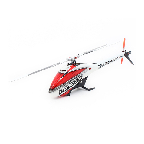
ALZRC DEVIL 380 FAST User manual

Instruction Manual
Version 1.0
Juny 2016
German market
english version

ALZRC DEVIL 380 FAST Manual
Version 1.0 - Juny 2016
Dongguan TONY Electronic Technology Co., Ltd.
www.alzrc.com
Attention: If you are a consumer and have questions or need of assistance,
please contact the retailer where you made the purchased first.
GERMAN DISTRIBUTION
www.kingsta-helis.com
Attention: If you are a consumer and have questions or need of assistance,
please contact the retailer where you made the purchased first.
MANUAL DEVIL 380
FAST
MANUAL DEVIL 380
FAST
CHAPTER 1 / INTRO PAGE 03
PAGE 02 WWW.ALZRC.COM

MANUAL DEVIL 380
FAST
MANUAL DEVIL 380
FAST
CHAPTER 1 / INTRO PAGE 03
PAGE 02 WWW.ALZRC.COM

MANUAL INDEX
PAGE 05 Specifications
06 Important Notes
07 Components and Box
08 Carbon frame Assembly
11 Transmission Assembly
13 Main Rotor Assembly
14 Assembling The Modules
15 Installation of Swashplate Servos
17 Tail Servo Assembly
18 Installation of The Motor
20 Installation of The ESC
22 Installation of Flybarless Unit and RX
23 Tail Assembly
26 Installation of the Boom, Canopy
29 Battery
30 In flight
31 Maintenance
32 Exploded view
1-SPECIFICATIONS
MANUAL INDEX
CHAPTER 1 / SPECIFICATIONS PAGE 05
PAGE 04 WWW.ALZRC.COM

1-SPECIFICATIONS
MANUAL INDEX
CHAPTER 1 / SPECIFICATIONS PAGE 05
PAGE 04 WWW.ALZRC.COM
SPECIFICATIONS
Main rotor diameter: 856 mm
Main blade length: 380 mm
Tail rotor diameter: 192 mm
Tail blade length: 70 mm
Main shaft diameter: 8 mm
Tail shaft diameter: 5 mm
Spindle diameter: 5 mm
Motor size: max. 41 mm diameter
max. height 41 mm
Battery
compartment: 44x44x130 mm

IMPORTANT NOTES
•This radio controlled helicopter is not a toy.
•This radio controlled helicopter can be very dangerous.
•This radio controlled helicopter is a technically complex device which has to be built and handled very carefully.
•This radio controlled helicopter must be built following these instructions. This manual provides the necessary
information to correctly assemble the model. It is necessary to carefully follow all the instructions.
•Inexperienced pilots must be monitored by expert pilots.
•All operators must wear safety glasses and take appropriate safety precautions.
•A radio controlled helicopter must only be used in open spaces without obstacles, and far enough from people to
minimize the possibility of accidents or of injury to property or persons.
•A radio controlled helicopter can behave in an unexpected manner, causing loss of control of the model, making it very
dangerous.
•Lack of care with assembly or maintenance can result in an unreliable and dangerous model.
•Neither ALZRC nor its agents have any control over the assembly, maintenance and use of this product.
•Therefore, no responsibility can be traced back to the manufacturer. You hereby agree to release ALZRC from
any responsibility or liability arising from the use of this product.
SAFETY GUIDELINES
•Fly only in areas dedicated to the use of model helicopters.
•Follow all control procedures for the radio frequency system.
•It is necessary that you know your radio system well. Check all functions of the transmitter before every flight.
•The blades of the model rotate at a very high speed; be aware of the danger they pose and the damage they may cause.
•Never fly in the vicinity of other people.
NOTES FOR ASSEMBLY
Please refer to this manual for assembly instructions for this model.
Follow the order of assembly indicated. The instructions are divided into chapters, which are structured in a way that
each step is based on the work done in the previous step. Changing the order of assembly may result in additional or
unnecessary steps.
Use thread lockers and retaining compounds as indicated. In general, each bolt or screw that engages with a metal part
requires thread lock.
It is necessary to pay attention to the symbols listed below:
3-COMPONENTS AND BOX
IMPORTANT NOTES
CHAPTER 3 / COMPONENTS AND BOX PAGE 07
PAGE 06 CHAPTER 2 / IMPORTANT NOTES
Use retaining
compound
(eg Loctite 648)
Use retaining
compound
(eg Loctite 243)
Use CA Glue Use Proper
Lubricant
Important

3-COMPONENTS AND BOX
IMPORTANT NOTES
CHAPTER 3 / COMPONENTS AND BOX PAGE 07
PAGE 06 CHAPTER 2 / IMPORTANT NOTES
ADDITIONAL COMPONENTS REQUIRED
•Electric Motor: 850 - 1000Kv:
Maximum diameter 41mm.
Maximum height 41mm.
Pinion shaft diameter 5 mm.
•Speed controller: minimum 60A,
extreme 3D Flight 70-90A.
•Batteries: 6S-1800 mAh ( 1500 - 2600 mAh ) .
•1 flybarless 3 axis control unit.
•Radio power system, if not integrated with the ESC.
•3 micro cyclic servos.
•1 mini (midi) tail rotor servo.
•6 channel radio control system on 2.4 GHz.
TOOLS, LUBRICANTS, ADHESIVES
•Generic pliers.
•Hexagonal driver, size 1.5,2,2.5mm.
•5.5mm Socket wrench (for M3 nuts).
•7mm Hex fork wrench (for M4 nuts).
•Medium threadlocker (eg. Loctite 243).
•Strong retaining compound (eg. Loctite 648).
•Spray lubricant (eg. Try-Flow Oil).
•Grease ( eg. Microlube GL261 ).
•Cyanoacrylate adhesive.
•Pitch Gauge (for set-up).
•Soldering equipment (for motor and ESC wiring).
INSIDE THE MAIN BOX THERE ARE:
MANUAL BOX 2
BOX 1
BOX 4
BOX 3
MAIN BOX
INSIDE THE MAIN BOX
BOX 1
Canopy
Frames
Blade Holder
Landing Gear
Battery Support
Tail Fin Assembly
BOX 2
Combo Components (Optional)
BOX 3
Tail boom
Carbon Rod
Blades + Tail Blades
BOX 4
Mechanical parts & Bags
The assembly process is described in the following chapters. Each chapter
provides you with the box and bag you will need for that chapter.
The information is printed at the bottom of every page.

4-CARBON FRAME
4-CARBON FRAME
CHAPTER 4 / CARBON FRAME PAGE 09
PAGE 08 CHAPTER 4 / CARBON FRAME
The manufacturing process of the carbon parts often leaves micro-burrs and sharp edges.
We recommend de-burring the edges to minimize the risks of electrical wire cuts, etc.
This is particularly important in the areas shown in red.

4-CARBON FRAME
4-CARBON FRAME
CHAPTER 4 / CARBON FRAME PAGE 09
PAGE 08 CHAPTER 4 / CARBON FRAME
LEFT MAIN FRAME ASSEMBLY
SUGGESTION
If you have the tail servo, we
suggest you install it at this time as
it will be more convenient to do so
before assembling the main frames.
Please refer to page 13 now for
more information.
RIGHT MAIN FRAME ASSEMBLY
NOTE
Use Loctite 243 to
lock the bolts in the
correct position.
Battery Aluminum Block
Button Head Cap
Screw M2x5mm
Main Frame
Button Head Cap
Special M2.5x6mm
Button Head Cap
Special M2.5x6mm
Button Head Cap
Special M2.5x6mm
Tail Servo
Support
Main Frame
Plastic Battery
Support

5-TRANSMISSION ASSEMBLY
4-CARBON FRAME
CHAPTER 5 / TRANSMISSION ASSEMBLY PAGE 11
PAGE 10 CHAPTER 4 / CARBON FRAME
MAIN FRAME ASSEMBLY
NOTE
Use Loctite 243 to
lock the bolts in the
correct position.
Button Head Cap
Special M2.5x6mm
Button Head Cap
Special M2.5x6mm
Button Head Cap
Special M2.5x6mm
Plastic
Landing gear
Finishing
Washer M2.5
Finishing
Washer M2.5
Socket Head Cap
Screw M2.5x10mm
Main Frame
Assembly

5-TRANSMISSION ASSEMBLY
4-CARBON FRAME
CHAPTER 5 / TRANSMISSION ASSEMBLY PAGE 11
PAGE 10 CHAPTER 4 / CARBON FRAME
SUGGESTION
Shims Ø8xØ12x0,1mm
(HC462-S)
Tighten the three screw M2.5.
After tightening, check the
axial play of the main shaft. It
is possible to reduce any axial play
by adding shims.
IMPORTANT:
Very carefully
check to make sure you can
turn the main shaft freely.
If you feel too much friction,
you have used too many
shims, you can remove a shim until
the shaft turns freely. Main Shaft
Main Plate
Main Shaft Assembly Main Shaft
Support
Socket Head Cap
Screw M2.5x8mm
Main Shaft Support
Assembly
Socket Head Cap
Screw M2.5x8mm
Socket Head Cap
Screw M2.5x8mm
Bearing Ø8xØ16x5mm
MAIN SHAFT
ASSEMBLY
MAIN SHAFT SUPPORT ASSEMBLY
Bearing Ø8xØ16x5mm
Already Assembled
Already Assembled

6-MAIN ROTOR ASSEMBLY
5-TRANSMISSION ASSEMBLY
CHAPTER 6 / MAIN ROTOR ASSEMBLY PAGE 13
PAGE 12 CHAPTER 5 / TRANSMISSION ASSEMBLY
MAIN FRAME ASSEMBLY
Socket Head Cap
Screw M2.5x6
120T Pulley
Assembly
120T PULLEY ASSEMBLY
120T Pulley
One Way Bearing
Ø8xØ12x12mm
Flanged Bearing
Ø8xØ12x3,5
Flanged Bearing
Ø8xØ12x3,5
Socket Head Cap
Screw M2x5
Socket Head Cap Screw
Shouldered M2.5x18mm
Plastic Servo Support
Main Plate
Assembly
Anti-Rotation
eg: Microlube GL261
NOTE
Add or remove shims to get
approximately 0.2-0.4mm play
Shims
Ø8xØ14x0,2mm
Socket Head Cap
Shoulder M2.5x15mm Front Tail Pulley
Assembly
FRONT TAIL PULLEY ASSEMBLY
Socket Head Cap
Screw M2x8mm
(HC008-S)
Front Tail Pulley
Assembly
Already Assembled

6-MAIN ROTOR ASSEMBLY
5-TRANSMISSION ASSEMBLY
CHAPTER 6 / MAIN ROTOR ASSEMBLY PAGE 13
PAGE 12 CHAPTER 5 / TRANSMISSION ASSEMBLY
Button Head Cap
Screw M4x6mm
Washer
ø 5x ø 7x0.1
Socket Head Cap
Screw M2x10mm
Radius Arm
Flanged Bearing
ø 2x ø 5x2.5mm
Flanged Bearing
ø 2x ø 5x2.5mm
Radius Plastic
Arm Assembly
RADIUS ARM ASSEMBLY ... X 2
Radius Arm
Assembly
NOTE:
Tighten with care, the arm must move freely.
RADIUS PLASTIC ARM ASSEMBLY ... X 2
Washer
ø 2.1x ø 5 x0.5mm
Radius Plastic Arm
NOTE:
eg: Microlube GL261
Inside:
Main Spindle
Center Hub
Oring Damper
CENTER HUB ASSEMBLY MAIN BLADE GRIP ASSEMBLY ....X2
Main Blade Grip
Socket Head Cap
Screw M2.5x8mm
Bearing
ø 5x ø 10x4mm
Uniball M2
HEAD HPS ASSEMLY
Bearing
ø 10x ø 19x5mm
Main Blade Grip
Assembly
Washer
ø 7.5x ø 10x0.5
Linkage Rod A
Socket Head Cap
Screw M2x10mm
NOTE:
We recommend assembling without shims for sport flying. However, for 3D flight or
high RPM, the best setup is assembling with at least one shim between the damper
and bearing.
After approximately 20/30 flights, please manually check the head dampening, you
can add one 0.1mm shim (HC450) if the dampening feels loose.
NOTE:
Larger ID inside
LINKAGE ROD A ASSEMBLY .....X2
Plastic Ball Link
Linkage Rod
M2x22mm
Plastic Ball Link
(Initial length for the rods from the
swashplate to the Blade Grip)

8-INSTALLATION OF SWASHPLATE SERVOS
7-ASSEMBLING THE MODULES
CHAPTER 8 / INSTALLATION OF SWASHPLATE SERVOS PAGE 15
PAGE 14 CHAPTER 7 / ASSEMBLING THE MODULES
SWASHPLATE ASSEMLY
Button Head Cap
Special M2.5x6mm
Uniball M2
Head Assembly
Metric Hex
Nylon Nuts M3
Swashplate
Assemly
Cup Point Set
Screws M4x20mm
Uniball M2 Uniball M2
Socket Head Cap
Shouldered M3x16mm
Swashplate
Assembly
Button Head Cap
Special M2.5x6mm
Button Head Cap
Special M2.5x6mm
Cup Point Set
Screws M4x20mm
NOTE:
Keep the distance between the end of the canopy
retainer H0542 and the frame at approximately 12mm.

8-INSTALLATION OF SWASHPLATE SERVOS
7-ASSEMBLING THE MODULES
CHAPTER 8 / INSTALLATION OF SWASHPLATE SERVOS PAGE 15
PAGE 14 CHAPTER 7 / ASSEMBLING THE MODULES
Uniball M2
Socket Head Cap
Screw M2.5x6mm
ALZRC Servo Arm
( Option)
INSTALLATION OF SWASHPLATE SERVOS
The linkage ball must be positioned approximately 13-15 mm out on the servo arm (figure 1), it is recommended to use the ALZRC / KST servo arm p/n [HA052]. Because of the
120° placement of the servos in the Devil380, the arms are difficult to access. For this reason it is advisable to ensure alignment of the servo arms (and sub trim) before installa-
tion of the servos in the model (figure 2). Proceed with installation following the instructions below. Figure 3 shows a completed installation.
The rods going from the servos to the swash plate must be as vertical as possible. (Red line in Figure 4). Not all servos are equal, so for proper alignment you can choose to use the
supplied spacer H0566 under the uniball H0538.
Servo 1
NOTE
:Do not over tighten,
be careful to not strip plastic.
Servo 2
Servo 3
NOTE
:Do not over tighten,
be careful to not strip plastic.
Button Head Cap
Screw M2x5mm
Button Head Cap
Screw M2x5mm

9-TAIL SERVO ASSEMBLY
8-INSTALLATION OF SWASHPLATE SERVOS
CHAPTER 9 / TAIL SERVO ASSEMBLY PAGE 17
PAGE 16 CHAPTER 8 / INSTALLATION OF SWASHPLATE SERVOS

9-TAIL SERVO ASSEMBLY
8-INSTALLATION OF SWASHPLATE SERVOS
CHAPTER 9 / TAIL SERVO ASSEMBLY PAGE 17
PAGE 16 CHAPTER 8 / INSTALLATION OF SWASHPLATE SERVOS
Servo Spacer
Socket Head Cap M3x6mm
Uniball M2 5H6
Tail servo
The distance between the servo spline and the ball
must be between 13-15 mm. You can use the
ALZRC servo horn.
Socket Head
Cap M2x8mm
Socket Head Cap
Screw M2.5x10mm
Servo Spacer
Socket Head Cap
Screw M2.5x10mm

10-INSTALLATION OF THE MOTOR
CHAPTER 10 / INSTALLATION OF THE MOTOR PAGE 19
PAGE 18 CHAPTER 10 / INSTALLATION OF THE MOTOR
It is important to choose the right reduction ratio to maximize efficiency based on your required flight performance.
It is possible to optimize any motor and battery combination.
It is recommended to use wiring and connectors appropriate for the currents generated in a helicopter of this class.
If you are using a head speed calculator which requires a main gear and pinion tooth count, use 120 teeth for the main gear and
the tooth count of your pulley as the pinion count.
Below is a list of available reduction ratios:
19T Pinion = ratio 6.3:1 22T Pinion = ratio 5.5:1
20T Pinion = ratio 6:1 23T Pinion = ratio 5.2:1
21T Pinion = ratio 5.7:1 24T Pinion = ratio 5:1
The Devil 380 accepts a wide selection of batteries with different capacities. The suggested number of cells is 6.
All batteries from 1500 to 2600 mAh offer good performance.
We recommend the use of an 1800 mAh battery for the perfect compromise between weight and performance (3D flight).
Larger capacity batteries (2200-2600) increase flight times at the expense of weight and reduced agility (Sport flight).
TRANSMISSION SETUP
CONFIGURATION
MOTOR ESC MOTOR PULLEY RPM MAX PITCH
NOTE
:Although the Devil can handle even higher RPMs, for safety reasons we suggest to not exceed 3600 RPM.

10-INSTALLATION OF THE MOTOR
CHAPTER 10 / INSTALLATION OF THE MOTOR PAGE 19
PAGE 18 CHAPTER 10 / INSTALLATION OF THE MOTOR
Cone Point Set
Screws M3x6mm
Motor Pulley 21T
Motor Support
Flat Head Socket
Cap M3x5mm
Motor
NOTE
:
Correct position for the motor wires.
Socket Head Cap
Screws M2.5x8mm
Metrix Hex
Nylon Nut M4
Finishing Washer M2.5
Cone Point Set
Screws M4x12mm
Socket Head Cap
Screws M2.5x8mm
Finishing Washer M2.5
Washer
ø 4.3x ø 11x1mm
NOTE
:
To maximize space for the batteries, it is
advisable to shorten the motor shaft.
Follow the dimensions given in this drawing.
For the cut, you can use an electric tool like a
“Dremel” with a cutoff disc.
Additionally, ensure the motor shaft has an
appropriate ‚flat‘ for one of the set screws.

11-INSTALLATION OF THE ESC
10-INSTALLATION OF THE MOTOR
CHAPTER 11 / INSTALLATION OF THE ESC PAGE 21
PAGE 20 CHAPTER 11 / INSTALLATION OF THE ESC
Belt 304-2GT-09
•Assemble the motor and pulley to its mounting plate.
•Install the motor assembly in the helicopter.
•It is easy to install the belt with the motor assembly pushed back towards the helicopter as far as it can go.
•First put the belt on the motor pulley.
•Then put the belt around the big pulley.
•Rotate the motor several times by hand.
•Pull and hold the motor slightly.
•Tighten the M4 nut first (It is suggested to use tool nut driver).
•The belt must be very tight.
•Tighten the rest of the bolts.
Motor Assembly
NOTE
:
Check for vertical alignment of the motor pulley. To do this, simply turn the motor several times by hand and check to you see if
the belt is aligned properly with the big pulley (one way bearing pulley).
If the belt is riding too high, simply loosen up the motor pulley and drop it just a little bit, if it is riding too low, loosen up the
motor pulley and raise it a bit.
CORRECT INCORRECT
MOTOR BELT TENSION
Other manuals for DEVIL 380 FAST
2
Table of contents
Other ALZRC Toy manuals
Popular Toy manuals by other brands

MGA Entertainment
MGA Entertainment BABY born SURPRISE Little Gems quick start guide

RACE TRACK SCENICS
RACE TRACK SCENICS 1S9 Assembly instructions

Estes
Estes GBU-24 PAVEWAY III EST 1247 instructions

Zhehua Toys
Zhehua Toys A730-2 instruction manual

Faller
Faller 130520 manual

roundhouse
roundhouse FOWLER Owner's handbook