manuals.online logo
Brands
  1. Home
  2. •
  3. Brands
  4. •
  5. Amada
  6. •
  7. Welding Accessories
  8. •
  9. Amada PULSETIG MAWA-300B Series User manual

Amada PULSETIG MAWA-300B Series User manual

This manual suits for next models

3

Other Amada Welding Accessories manuals

Amada MK-110B User manual

Amada

Amada MK-110B User manual

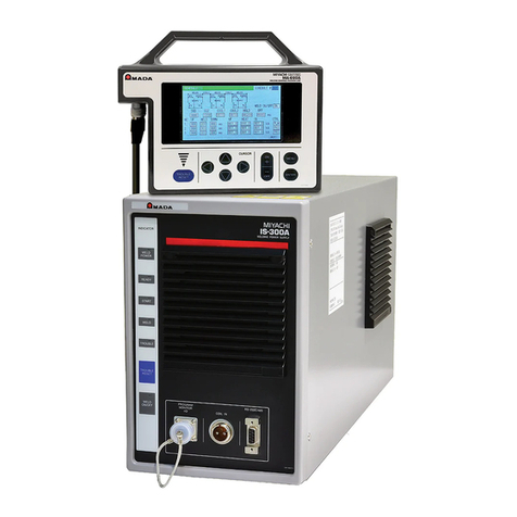
Amada IS-300A User manual

Amada

Amada IS-300A User manual

Amada Thin-Line TL-080B Series User manual

Amada

Amada Thin-Line TL-080B Series User manual

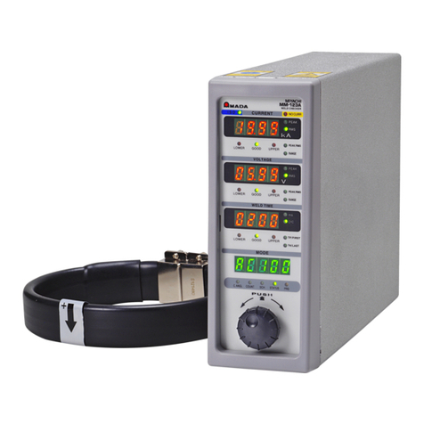
Amada WELD CHECKER MM-123A User manual

Amada

Amada WELD CHECKER MM-123A User manual

Amada MK-108B User manual

Amada

Amada MK-108B User manual

Amada IS-200A User manual

Amada

Amada IS-200A User manual

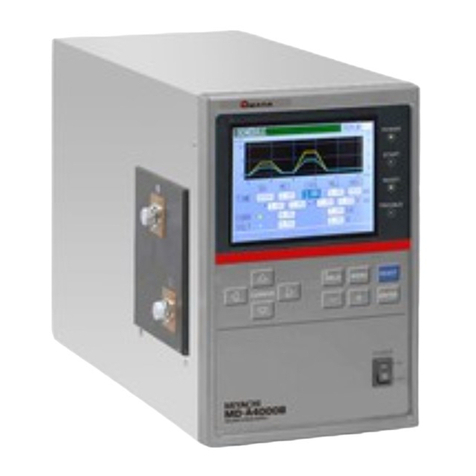
Amada MD-A4000B-05 Series User manual

Amada

Amada MD-A4000B-05 Series User manual

Amada MM-122A User manual

Amada

Amada MM-122A User manual

Amada SR-071A User manual

Amada

Amada SR-071A User manual

Amada WELTOUCH CT-110D User manual

Amada

Amada WELTOUCH CT-110D User manual

Amada MacGregor DC 13-T Series User manual

Amada

Amada MacGregor DC 13-T Series User manual

Amada WELD SENTRY User manual

Amada

Amada WELD SENTRY User manual

Amada WELTOUCH CY-210E User manual

Amada

Amada WELTOUCH CY-210E User manual

Amada Miyachi PA-T0200A User manual

Amada

Amada Miyachi PA-T0200A User manual

Amada FX Series User manual

Amada

Amada FX Series User manual

Amada WELTOUCH CY-210D User manual

Amada

Amada WELTOUCH CY-210D User manual

Amada MH-1201A User manual

Amada

Amada MH-1201A User manual

Amada MM-140A User manual

Amada

Amada MM-140A User manual

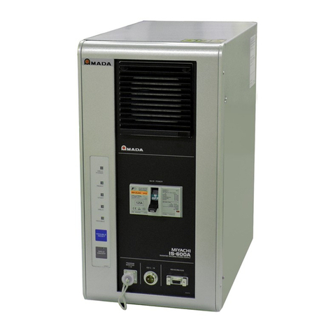
Amada IS-600A User manual

Amada

Amada IS-600A User manual

Amada VT-SS User manual

Amada

Amada VT-SS User manual

Amada MH-P20B-2 Series User manual

Amada

Amada MH-P20B-2 Series User manual

Amada MH-21AC User manual

Amada

Amada MH-21AC User manual

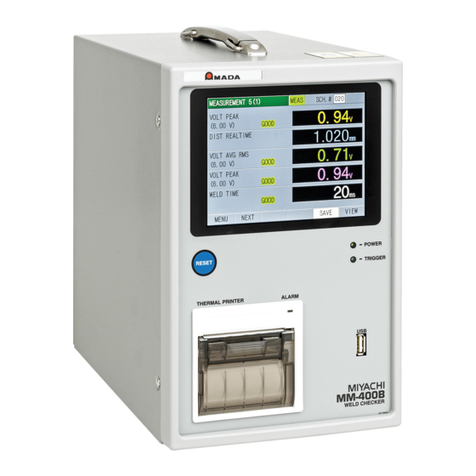
Amada WELD CHECKER MM-400B User manual

Amada

Amada WELD CHECKER MM-400B User manual

Amada MM-601B User manual

Amada

Amada MM-601B User manual

Popular Welding Accessories manuals by other brands

RelFar FWH20-S10A manual

RelFar

RelFar FWH20-S10A manual

Lincoln Electric LT-7 Tractor Technical specifications

Lincoln Electric

Lincoln Electric LT-7 Tractor Technical specifications

Cornwell Tools MMWC1 Operator's manual

Cornwell Tools

Cornwell Tools MMWC1 Operator's manual

Dohle ExOn2A operating instructions

Dohle

Dohle ExOn2A operating instructions

Nederman Fume Eliminator FE 840/2500/P150 user manual

Nederman

Nederman Fume Eliminator FE 840/2500/P150 user manual

3M Speedglas 9100 Series user manual

3M

3M Speedglas 9100 Series user manual

Miller Electric OM-842 owner's manual

Miller Electric

Miller Electric OM-842 owner's manual

Miller A-200 Series owner's manual

Miller

Miller A-200 Series owner's manual

Abicor Binzel ABIMIG WT Series operating instructions

Abicor Binzel

Abicor Binzel ABIMIG WT Series operating instructions

Miller MIGmatic M-25 owner's manual

Miller

Miller MIGmatic M-25 owner's manual

Abicor Binzel xFUME PRO Original operating instructions

Abicor Binzel

Abicor Binzel xFUME PRO Original operating instructions

iWeld NORED EYE user manual

iWeld

iWeld NORED EYE user manual

Sthor 74483 manual

Sthor

Sthor 74483 manual

Miller I-22 CE owner's manual

Miller

Miller I-22 CE owner's manual

LAHTI PRO L1540400 instruction manual

LAHTI PRO

LAHTI PRO L1540400 instruction manual

Lincoln Electric K3091-1 Operator's manual

Lincoln Electric

Lincoln Electric K3091-1 Operator's manual

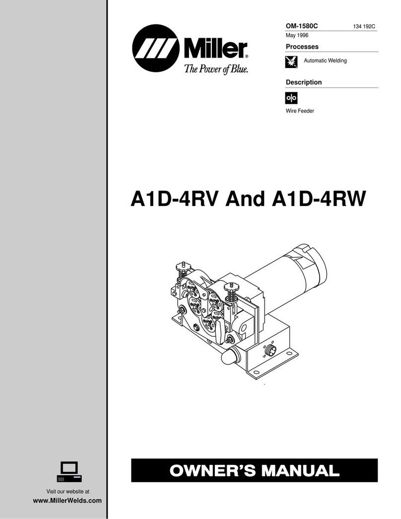
Miller Electric A1D-4RV owner's manual

Miller Electric

Miller Electric A1D-4RV owner's manual

Tregaskiss TOUGH GUN TT3 Reamer owner's manual

Tregaskiss

Tregaskiss TOUGH GUN TT3 Reamer owner's manual

manuals.online logo
manuals.online logoBrands
  • About & Mission
  • Contact us
  • Privacy Policy
  • Terms and Conditions

Copyright 2025 Manuals.Online. All Rights Reserved.

U12OM1190506-01
OPERATION MANUAL
PULSETIG® WELDING POWER SUPPLY
MAWA-300B
MAWA-300B
Contents
i
Thank you for purchasing the Amada Miyachi PULSETIG®Welding Power Supply MAWA-300B.
This operation manual describes its method of operation and precautions for use.
Read this operation manual carefully prior to use. Store appropriately for ready reference.
Contents
Notification of Risk Information
(1) Responsibility for Overall Management ····································································· 2
(1) -1. Observance of laws, regulations and safety standard related to
the pulse TIG welding machine ····························································· 2
(1) -2. Execution of safety and health education ·············································· 2
(1) -3. Clothes for operations ··········································································· 2
(2) Prohibition of Disassembly, Repair and Modification of the Welding Power Supply · 2
(3) Map of Residual Risks ······························································································· 3
(3) -1. Map of residual risks of the welding power supply unit·························· 3
(3) -2. Map of residual risks of the standard system········································· 4
(4) Table of Residual Risks······························································································ 5
(4) -1. Installation ····························································································· 5
(4) -2. Machine operation ················································································· 7
(4) -3. Maintenance ··························································································11
(4) -4. Scrapping ····························································································· 13
(5) On Disposal··············································································································· 14
(6) Warning Labels ········································································································· 14
1. Overview
(1) Features ····················································································································1-1
(2) Names of Parts ·········································································································1-2
(2) -1. Front panel ···························································································1-2
(2) -2. Rear panel ····························································································1-3
(3) Specifications ············································································································1-4
(3) -1. Product specifications···········································································1-4
(3) -2. Product dimensions ··············································································1-8
(3) -2-1. Main unit························································································1-8
(3) -2-2. Panel unit ······················································································1-8
(3) -3. Duty cycle graph···················································································1-9
(4) Operational Principle Diagram ·················································································1-10
(5) Main Parts List ·········································································································1-10
(6) Accessories··············································································································1-10
(7) Options·····················································································································1-11
2. Installation and Connections
(1) Installing Conditions ··································································································2-1
(2) Connections ··············································································································2-3
This operation manual is common to both MAWA-300B-00-00 and MAWA-300B-00-01.
MAWA-300B-00-00 is used in the explanatory drawings unless there is a significant
difference.
ATTENTION
MAWA-300B
Contents
ii
(2) -1. Preparation for connections··································································2-3
(2) -2. Connecting the power supply ·······························································2-5
(2) -3. Connecting the ground ·········································································2-7
(2) -4. Connecting the torch ············································································2-9
(2) -4-1. Improvement against an accidental fire········································ 2-11
(2) -5. Connecting the argon gas····································································2-12
(2) -6. Connecting the external input/output devices ······································2-13
(2) -7. Connecting the external communication device ··································2-14
(2) -8. Connecting the torch head for touch start············································2-15
(2) -9. Removing the panel unit ······································································2-16
(3) Interface ···················································································································2-19
(3) -1. Explanation of external input/output signals ········································2-19
(3) -1-1. Input connector (D-Sub 37-pin, female) ·······································2-19
(3) -1-2. Output connector (D-Sub 25-pin, female)·····································2-21
(3) -1-3. Option input/output connector (D-Sub 25-pin, male) ····················2-22
(3) -1-4. Current/voltage monitor connector (D-Sub 15-pin, female) ··········2-23
(3) -2. Connection diagram of external input/output signals ···························2-24
(3) -2-1. Input connector (D-Sub 37-pin, female) ·······································2-24
(3) -2-2. Output connector (D-Sub 25-pin, female)·····································2-25
(3) -2-3. Option input/output connector (D-Sub 25-pin, male) ····················2-26
(3) -3. External input/output signal table·························································2-27
(3) -3-1. User input terminals ·····································································2-27
(3) -3-2. User output terminals ···································································2-28
(3) -4. Input signal connecting method ···························································2-30
3. Operating Unit
(1) Front Panel················································································································3-1
4. Explanation of Screens
(1) Screen Structure ·······································································································4-1
(2) Menu Screen·············································································································4-3
(3) Monitor Screen··········································································································4-5
(4) Envelope Screen······································································································4-10
(5) Basic Setting Screen································································································4-15
(6) Switch Select Screen ·······························································································4-17
(7) Initialize Memory Screen··························································································4-21
(8) External I/O Setting Screen ·····················································································4-22
(9) Welding Condition Setting Screen ···········································································4-23
(10) Schedule Setting Screen··························································································4-27
(11) Monitor Select Screen······························································································4-30
(12) Upper/Lower Limit Set Screen ·················································································4-32
(13) SCH Copy Screen····································································································4-33
(14) External I/O Check Screen ······················································································4-36
(15) Count Setting Screen ·······························································································4-39
(16) Error History Screen·································································································4-40
(17) Password Setting Screen·························································································4-41
(18) Maintenance Screen ································································································4-42
(19) Set Values of Each Screen at Delivery from the Factory·········································4-43
5. Welding
(1) Pre-Start Inspection···································································································5-1
(2) Turning on the Power Supply····················································································5-2

MAWA-300B
Contents
iii
(3) Basic Function Setting ······························································································5-3
(3) -1. Common detail item setting ··································································5-4
(4) Welding Condition Setting·························································································5-5
(4) -1. Registering the welding conditions ·······················································5-5
(4) -2. Welding current pulse modulation setting ·············································5-6
(4) -3. Welding condition copy·········································································5-7
(5) Monitor Function Setting ···························································································5-8
(5) -1. Monitor item setting ··············································································5-8
(5) -2. Upper/lower limit value setting······························································5-9
(6) Touch Start ···············································································································5-10
(6) -1. Overview······························································································5-10
(6) -2. Operations ···························································································5-10
(6) -2-1. Normal mode················································································ 5-11
(6) -2-2. Auto mode····················································································5-12
(6) -2-3. Fine weld mode············································································5-13
(6) -3. Adjustment···························································································5-14
(6) -4. Start using an external input/output signal ···········································5-14
(7) Preparation for Starting Welding ··············································································5-15
(8) Checking and Registering the Envelope Waveform Data········································5-16
(9) Shutting off the Power Supply··················································································5-17
6. Timing Chart
(1) Touch Start (servo motor type welding head)····························································6-1
(2) Touch Start (when the customer-prepared motor head is used)·······························6-2
(3) Touch Start (when the auto mode is set)···································································6-3
(4) Touch Start (when the fine weld mode is set) ···························································6-4
(5) Touch Start (at occurrence of LOST) ········································································6-5
(6) Touch Start (air type welding head)···········································································6-6
(7) Touch Start Option Input/Output Signals···································································6-7
(8) High-voltage Start······································································································6-9
(9) High-voltage Start (at occurrence of LOST)·····························································6-11
(10) Schedule Changeover······························································································6-13
(11) Schedule No. and SCH Select Terminals ································································6-14
7. External Communication Function
(1) Overview ···················································································································7-1
(2) Data Transfer ············································································································7-1
(3) Configuration·············································································································7-2
(4) Protocol ·····················································································································7-3
(5) Data Code Table········································································································7-7
8. Troubleshooting
(1) Error Screen··············································································································8-1
(2) Error Messages·········································································································8-2
(3) Error other than Above······························································································8-5
9. Maintenance
(1) Pre-Start Inspection···································································································9-1
(1) -1. Cable inspection ···················································································9-1
(1) -2. Torch inspection····················································································9-1
(1) -3. Argon gas inspection ············································································9-1
(2) Periodic Maintenance································································································9-3
MAWA-300B
Contents
iv
(2) -1. Monthly maintenance ···········································································9-3
(2) -1-1. Cleaning the cooling fan filter ························································9-3
MAWA-300B
Notification of Risk Information
1
Notification of Risk Information
This “Notification of Risk Information” is intended to notify the risk or others related to this machine
(Ordinance on Industrial Safety and Health, Article 24-13) so as to promote the execution of risk
assessment (Industrial Safety and Health Act, Article 28-2) on the enterprise side for prevention of
labor disasters.
The risk map and residual risk table in this chapter include the matters to be described which are
specified in the guide (Notification No.132 of the Ministry of Health, Labor and Welfare issued in
2012) related to the promotion of notice of the risk or others on the machine by the transferor of the
machine.
This chapter is a part of the operation manual. Accordingly, do not operate the machine with an
understanding of only this chapter. Be sure to read through all the operation manual with a good
understanding of its contents before operating the machine.
In this “Notification of Risk Information” and the operation manual, “Injury Levels” are classified
according to the following definitions.
WARNING This indicates the existence of potential hazard which, if not avoided, may
result in death or serious injury of a personal.
CAUTION This indicates the existence of potential hazard which, if not avoided, may
result in a less serious injury of a personal.
MAWA-300B
Notification of Risk Information
2
(1) Responsibility for Overall Management
(1) -1. Observance of laws, regulations and safety standard related to the
pulse TIG welding machine
When selecting an installation place of the pulse TIG welding machine, performing the
power supply work on the input side, handling and taking charge of high-pressure gas, and
taking charge of products after welding, and disposing wastes, please observe the laws,
regulations and safety standard of your company.
(1) -2. Execution of safety and health education
For the operator of the pulse TIG welding machine, give a special education of arc welding.
(Labor Safety and Health Regulations, Article 36)
In particular, execute an education and training about the following items.
yStructure of the pulse TIG welding machine
yHow to handle the pulse TIG welding machine
yPerformance and handling of the light-shielding protector
yMeasures to be taken in an emergency
yProhibition of using the machine for other purposes than welding
(1) -3. Clothes for operations
For executing welding operations, put on clothes with long sleeves, foot covers, leather
protective globes, and other protectors such as apron. If scattered wastes (spatters) are
directly applied to the skin, this will result in a burn.
In accordance with the contents of each operation, put on an appropriate protector such as
safety cap, protective glasses and dust-proof mask.
Select each protector based on the safety standard for each operation.
(2) Prohibition of Disassembly, Repair and Modification of
the Welding Power Supply
A high voltage is applied to the inside of the welding power supply. Even after the supply power to
the welding power supply is shut off, a high voltage status is kept for a certain time. If the case of
the welding power supply is removed, this may result in a serious accident. Do not operate the
machine in the status where the terminal cover on the rear side of the welding power supply is
removed.
MAWA-300B
Notification of Risk Information
3
(3) Map of Residual Risks
For the details of various residual risks, refer to “(4) Table of Residual Risks.”
(3) -1. Map of residual risks of the welding power supply unit
Terminal cover
- Collapse
Welding power supply unit and welding power supply inside
- Electric shock
Input terminal and output terminal
- Electric shock
Input cable and connection cable
- Electric shock
Output cable (torch cable and grounding cable)
- Electric shock
Terminal cover
- Collapse
Emergency stop button
Main power switch
Welding power supply fan
- Rolling-in
Residual risk No.
Source of danger
Result of the source of
danger
1
Explanation of the map (example)
MAWA-300B
Notification of Risk Information
4
(3) -2. Map of residual risks of the standard system
(Welding power supply + Torch + Torch driving unit + Wire supply unit)
Remarks
yThis is supposed on the case where the standard welding machine is incorporated.
Execute risk assessment by using the customer’s actual specification.
Argon gas
- Poisoning
- Suffocation
Gas cylinder
- Collapse
Gas flow rate adjuster
- Breakage
Dust and argon gas
- Poisoning
- Suffocation
- Respiratory trouble
Wire supply unit
- Rolling-in
- Fire
Emergency stop button
Main power switch
Emergency stop button
Electrode and torch
- Electric shock
Gas generated from workpiece
- Respiratory trouble
Combustible
- Fire
- Explosion
Dust
- Fire
- Respiratory
Electromagnetic wave from the vicinity of
the welding power supply and torch
- Effect on the medical devices in the body
Arc light
- Optic trouble
- Burn
Welding jig
- Electric shock
Workpiece and electrode immediately after welding
- Burn
1
Explanation of the map (example)
- Collapse
Terminal cover
Residual risk No.
Source of danger
Result of the source of
danger
MAWA-300B
Notification of Risk Information
5
(4) Table of Residual Risks
For concrete positions of residual risks, refer to “(3) Map of Residual Risks.”
(4) -1. Installation
1 WARNING Transporting the welding power supply
[Source of risk] Terminal cover
[Contents of risk] If the welding power supply is transported by holding such a
projection as the terminal cover, the foot may be collapsed if it is
fallen down.
[Protective measure] When transporting the welding power supply by holding it with
hands, hold its bottom.
2 WARNING Installing the welding power supply
[Source of risk] Arc light
[Contents of risk] In the pulse TIG welding machine, strong arc light will be scattered
at welding. If this arc light is caught by eyes, the eyes may be
inflamed.
[Protective measure] Install a light-shielding partition or light-shielding curtain around
the welding machine to mark off the welding work place so that arc
light may not be applied to the human eyes directly. (Ordinance
on Industrial Safety and Hygiene, Article 325)
3 WARNING Electric wiring
[Source of risk] Welding power supply unit
[Contents of risk] Unless the specified primary supply voltage and Class D
grounding work are omitted, an electric shock may be caused by
electric leakage or by high voltage due to mis-operation.
[Protective measure] Execute the primary power supply work and grounding work
according to the electric connection diagram. Connect the
welding power supply to the ground independently.