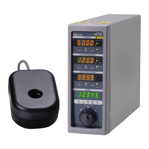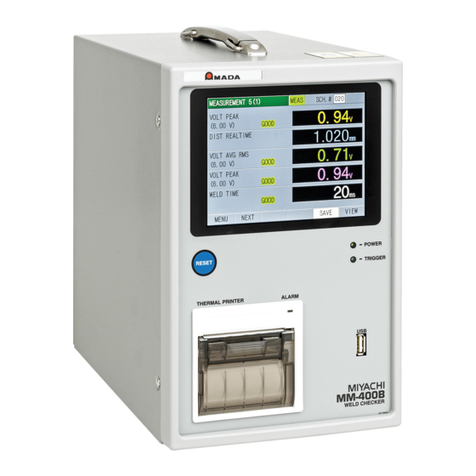
MM-123A
Contents
2
e. Selecting Peak or Effective Value of Voltage .....................................................................................7-13
f. Selecting the Voltage Range .............................................................................................................7-14
g. Setting the Measurement Start Time (FIRST) and the Measurement End Time (LAST) ...................7-15
h. Selecting TP/TH (in the current measurement mode CAP-S and CAP-L only)..................................7-18
(4) Upper/Lower Limit Judgment Function ...................................................................... 7-20
a. Setting the Upper and Lower Limits of the Current ............................................................................7-20
b. Setting the Upper and Lower Limits of the Voltage ............................................................................7-22
c. Setting the Upper and Lower Limits of the Weld Time .......................................................................7-24
(5) Settings in the Program Mode ................................................................................... 7-26
a. Setting the Preset Counter (COUNT).................................................................................................7-26
b. Setting the Step Counter....................................................................................................................7-27
c. STATUS Setting ................................................................................................................................7-29
d. Difference between the Original Mode and the ISO17657-compliant Mode ......................................7-30
e. Setting the Various Levels .................................................................................................................7-32
f. Impulse Measurement .......................................................................................................................7-34
g. Communication Setting......................................................................................................................7-36
h. System Setting...................................................................................................................................7-39
i. Setting the Upper/Lower Limit Judgment when Using the Step Counter Function.............................7-44
j. Password Setting ...............................................................................................................................7-46
(6) Checking Settings and Initializing.............................................................................. 7-48
a. Checking the Setting and the Previously Measured Value ................................................................7-48
b. Initializing the Schedule Setting .........................................................................................................7-49
8. Data Communication ...................................................................................................... 8-1
(1) Data Transfer............................................................................................................... 8-1
(2) Configuration ............................................................................................................... 8-1
(3) Communication Protocol (Single-Directional Communication) .................................... 8-5
a. Monitor Data ........................................................................................................................................8-5
b. Error Data ............................................................................................................................................8-9
(4) Communication Protocol (Bi-Directional Communication)......................................... 8-10
a. Reading the Monitor Data ..................................................................................................................8-10
b. Reading and Writing the Upper and Lower Limit Value Data of Current ............................................8-12
c. Reading and Writing the Upper and Lower Limit Value Data of Current of Each Step.......................8-14
d. Reading and Writing the Upper and Lower Limit Value Data of Voltage............................................8-19
e. Reading and Writing the Upper and Lower Limit Value Data of Voltage of Each Step ......................8-21
f. Reading and Writing the Upper and Lower Limit Value Data of Weld Time.......................................8-25
g. Reading and Writing the Upper and Lower Limit Value Data of Weld Time (TP/TH) .........................8-28
h. Reading and Writing the System Setting Data...................................................................................8-30
i. Reading and Writing the Counter Data of Each Step.........................................................................8-34
j. Reading and Writing the I/O Setting Data ..........................................................................................8-36
k. Reading and Writing the Communication Setting Data ......................................................................8-38
9. Fault Code List ................................................................................................................ 9-1
10. Specifications ................................................................................................................ 10-1
(1) Measurement Specification ....................................................................................... 10-1
(2) Specification of the MM-123A.................................................................................... 10-5
11. Calibration...................................................................................................................... 11-1
12. Outline Drawing............................................................................................................. 12-1
(1) Body .......................................................................................................................... 12-1
(2) Drawings for Mounting Bracket.................................................................................. 12-2
a. Front and Rear Mounting ...................................................................................................................12-2
b. Right and Left Mounting.....................................................................................................................12-2
Index............................................................................................................................................1
EU Declaration of Conformity

