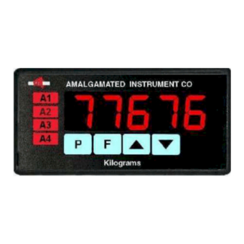
AMALGAMATED INSTRUMENT PM5-TR Guide

Model PM5-TR
Ratemeter/Totaliser
Panel Mount Display/Controller
Operation and Instruction Manual
AMALGAMATED INSTRUMENT CO ABN: 80 619 963 692
NSW 2077 Australia Facsimile: +61 2 9476 2902 Internet: www.aicpl.com.au

1 Introduction
General description
This manual contains information for the installation and operation of the the PM5-TR Monitor.
The instrument may be set to operate as a ratemeter or totaliser or allow toggling between rate and
total displays. A “grand total” display is also viewable and can be separately reset. The OPEr
function allows selection of one of these three modes. A brief description of each mode is given
below. The “Explanation of functions” chapter details functions available for all modes, consult
the separate function table for each mode to view the available functions for these modes.
The 5 digit display version has 4 annunciator LED’s on the front panel. These LED’s indicate which
alarm is activated, not necessarily the relay activated. When in alarm condition the annunciator
will flash. If the Fbutton is pressed and the alarm is still in alarm condition the annunciator for
that alarm will be solidly lit. The annunciator will extinguish only when outside of alarm condition.
This applies even if the relay selected by the alarm has itself been acknowledged and reset.
Up to 8 alarms can be set and each alarm can be set to operate from either the rate or total value.
The three modes of operation relevant to this manual selectable at the OPEr function are:
1. totL - totaliser/counter display. The input pulses are totalised, scaled in engineering units
and displayed e.g. Total litres, mm etc. Count up or count down is possible. A total and
grand total may be viewed and reset separately. The grand total is a separate total memory
which allows storage of all the previous totals. If a front Pbutton is fitted this can be
programmed to reset the total or set it to a preset. If no Pbutton is fitted then remote
input 1 or 2 can be programmed to force the display to reset or to go to the preset value.
2. RAtE - frequency/rate display. The frequency or rate of the input may be scaled in engineer-
ing units and displayed e.g. R.P.M., Bottles/min., Litres/hour etc.. For frequencies below
1kHz there is a choice of displaying rate, averaged rate or rolling average rate each of which
are scaleable.
3. both - total/rate display (display may be toggled to either total or rate) This mode is
primarily used when the display is required to toggle between a rate and total display via
an external contact closure or via the front panel ^and vbuttons (only fitted on certain
display options). A total and grand total may be viewed and reset separately.
Up/Down count totalising
The The tOt dir function can be used to select up (UP) or down (doWn) counting or input 2
can be used to control the down direction as described below.
Input 2 can be set to control whether the pulses on input 1 cause the total to increase or decrease.
The tOt dir function must be set to UP.dn for this input to be used. Input 2 is configured by
the IN 2 group of functions
Rate scaling methods
Three different methods are provided for scaling the rate display, the selection is made at the USER
CAL function. Refer to the individual functions in the “Explanation of Functions” chapter for
further description.
1. INPt - with this method values for INPt and SCL are entered to provide the correct scaling.
e.g. for a scaling in RPM with 100 pulses per revolution the INPt function will be set to 100 and
the SCL to 60.
PM5TRMAN-1.7-0 3 of 73

2. USER - with this method the user enters two frequencies via the pushbuttons and applies a
scale value to each frequency. The CAL IN 1 and CAL SCL.1 functions are used to set the first
frequency and the CAL IN 2 and CAL SCL.2 functions are used to set the second frequency.
The display takes these two points as points in a straight line for calculating and displaying inputs
above, between and below these two points. For example if it is required that for a zero Hz input
the display should show 100 and at a frequency of 500Hz the display should show a frequency of
1000 then CAL IN 1 would be set to 0, CAL SCL.1 would be set to 100 and CAL IN 2 would
be set to 500 with CAL SCL.2 set to 1000.
3. LIUE - using this method two live frequency inputs need to be applied and scale values are set
for each input. The two frequencies are applied at the CAL1 and CAL2 and a scale value SCLE
value will be asked for at each input. When using this method a single point offset can also be
applied to the scaling at the OFSt function.
1.1 Selecting and altering access levels
This subsection details the use ”access levels”. Access levels can be used to obtain easy access to
functions which are regularly required and to limit access to functions which are not required or
which restricted access is required. These access level settings can be ignored if no restrictions to
access are required and no easy access to selected functions is required.
Each setup function has a default access level allocated to it, for example the relay 1 high alarm
function AL1 high is allocated a default level of 2. There is a facility for the user to change the
access levels for a limited number of functions to make them either easier to access or harder to
access as required, see the Fn.1 CodE function.
There are different ways of accessing setup functions, these are explained in the following section.
Each mode allows a selection of access levels i.e. allows some choice of which functions are accessible.
The access levels available are:
None - no access to functions
1- access to functions allocated to level 1
2- access to functions allocated to level 2
3- access to functions allocated to level 3
4- access to functions allocated to level 4
5- access to functions allocated to level 5
6- access to functions allocated to level 6
CAL - access to all normal operation functions
1.2 Accessing setup functions
The setup functions allow adjustment of the instruments operation functions. There are five dif-
ferent ways of accessing setup functions. Each mode allows a selection of access levels i.e. allows
some choice of which functions are accessible.
As as summary the methods available are:
•Easy mode - this is the easiest access mode simply requiring the Fbutton to be pressed
for 3 seconds. This mode would normally be used to gain access to functions which require
frequent adjustment.
4 of 73 PM5TRMAN-1.7-0
•Remote input mode - this uses the Easy method of access but also requires the use of a
remote input switch.
•PIN 1 mode - this method allows a PIN to be set with access via PIN entry.
•PIN 2 mode - this method also requires a PIN and would generally be use to allow a higher
access level than the first PIN.
•Super Cal mode - this method requires a power up procedure and will allow access to all
functions.
These modes are explained in more detail below.
•Easy mode - Allows access to the level set by the EASY LEUL function in the
ACCS menu. By default the Easy access is set to NONE which blocks access to all setup
functions. To allow access to functions using this method choose the access level required at
the EASY LEUL function.
The Easy mode simply requires that the Fbutton is held pressed until the message FUNC
is seen followed by the first function message, this should take approximately 3 seconds. If
the message FUNC End or no response is seen at this point it means that the access level
has been set to NONE. The default access for this level is NONE so the access level will need
to be changed if access via this method is required.
P F
Press and
hold F for
approx.
3 seconds
Easy mode
•Remote input mode - Allows access to the level set by the R.INP LEUL function in the
ACCS menu. By default the Remote input access is set to CAL level allowing access to all
setup functions.
The remote input mode uses the same access method as the Easy mode but also requires
that one of the available remote inputs is set to ACCSS and that the selected remote input
is activated i.e. shorted to GND. The default access for this level is NONE so the access level
will need to be changed if access via this method is required.
P F
Press and
hold F for
approx.
3 seconds
Also requires that the selected
remote input is set to ACCSS
and is activated.
Remote input
mode
•PIN 1 mode - Allows access to the level set by the USR.1 LEUL function in the
ACCS menu.
The PIN 1 mode requires the Fbutton is pressed and released then within 2 seconds press
the ^and vbuttons at the same time. The PIN can be set via the USR.1 Pin function
in the ACCS menu. A USR.1 LEUL setting of 0disables the PIN which means that there
is no need to enter the PIN. If the USR.1 LEUL function has been set to a number other
than NonE then the first function seen when entering via PIN 1 mode will be the function
PM5TRMAN-1.7-0 5 of 73

CodE. When this function is seen the PIN value set at the USR.1 Pin function must be
entered via the ^or vpushbuttons followed by pressing Fto accept the PIN before the
user can progress to the setup functions.
P
P
F
F
Press and
release F then:
If a PIN has been set the
message Code will be seen.
Use ^ or v to enter the PIN
then press F to accept the PIN.
Press and
release Up
and Down
simultaneously
PIN 1
and
PIN 2
mode
•PIN 2 mode - Allows access to the level set by the USR.2 LEUL function in the
ACCS menu.
This method uses the same access method as PIN 1 mode above. A USR.2 Pin setting
of 0disables the PIN. If the USR.1 LEUL or a USR.2 Pin function has been set to a
number other than 0then the first function seen when entering via PIN 1/PIN2 mode will
be the function CodE. When this function is seen the PIN value set at the USR.1 Pin
function can be entered for access to the level set at the USR.1 LEUL function or enter the
USR.2 Pin PIN to gain access to the level set at the USR.2 LEUL function. A correct
code will allow access to the functions at the selected level. An incorrect code will result
in the FUNC End message being seen indicating that access to setup functions has been
refused and the display will return to normal measurement mode.
•Super Cal mode - This method can be used to gain access to all functions. If a PIN has
been set and forgotten use this method to access the PIN functions to check the settings. To
access via Super Cal mode with the instrument switched off hold in the Fbutton whilst the
instrument powers up. Keep the button pressed until the S.CAL message is seen, you can
then release the Fbutton. Next press and release Fthen within 2 seconds press and release
the ^and vpushbuttons simultaneously.
P
P
P
F
F
F
Press and
release F then:
Hold F when
powering up,
wait for S.CAL
message then
release F then:
Press and
release Up
and Down
simultaneously
Super Cal
mode
6 of 73 PM5TRMAN-1.7-0

The setup functions are organised in blocks or sections e.g. all the settings for channel 1 alarms are
in the AL1 section. Once access to setup functions has been gained use the ^and vbuttons to
select the section required then press Fto enter this section and again us the ^and vbuttons
to select the required function for alteration and press Fto allow alteration of this function.
Typical sections for a basic instrument are illustrated below. In any particular instrument addi-
tional sections may appear depending on the part number and any optional outputs fitted.
Relay setup
functions
e.g. AL1
Relay mode
functions
e.g. RLY1
Operation
functions
e.g. OPEr
Input setup
functions
e.g. RAtE
Input
functions
e.g. INP 1
Etc.
Excitation setup
functions
e.g. P.Out
Use ^ or v to move to
the section required then
press F to access the
functions in that section.
Press P to escape the
section you are in or
press F at the End
function in the section.
Remote input/
P button setup
functions R.INP
PM5TRMAN-1.7-0 7 of 73

The example in the flowchart (for 4 digit display) below shows the method using alarm relay 1
setup function.
Use ^ or v to adjust
to any setting or press
^ and v together to disable
and set to OFF. Press F to
accept the change.
Use ^ or v to adjust
to any setting or press
^ and v together to disable
and set to OFF.
accept the change.
Press F to
Use ^ or v to adjust,
range 0 to 9999. Press F to
accept the change.
Use ^ or v to adjust,
range 0.0 to 999.9. Press
F to accept the change.
Use ^ or v to adjust,
range 0.0 to 999.9. Press
F to accept the change.
Use ^ or v to choose the
required relay then use
F to select or
Use or to until is seen.
Press F to accept the change.
On OFF.
^ v End
Choose the channel RAte or totL.
Press F to accept the change.
Use ^ or v to choose
Latch or Auto
Press F to accept the change.
Use ^ or
v to move
between the
alarm 2
settings
Press F
to go to
To go to
back to
measurement
display
press P
or use ^
or v
to go to
End then
press F
To scroll
through
to other main
sections
press ^
or v
Alarm 2
setting section
Settings for
alarm 2
Press F to
go to setting
Press F to
go to setting
Press F to
go to setting
Followed by
the setting
Followed by
the setting
Followed by
the setting
Followed by
the setting
Followed by
the setting
Followed by
the setting
Followed by
the setting
Followed by
the setting
Press F to
go to setting
Press F to
go to setting
Press F to
go to setting
Press F to
go to setting
Press F to
go to setting
Press F or P to return to
the beginning of the section
AL 2 HiGh
Lo
HySt
triP
RSt
RLYS
Ch
Ltch
End
8 of 73 PM5TRMAN-1.7-0

2 Mechanical Installation
Choose a mounting position as far away as possible from sources of electrical noise such as motors,
generators, fluorescent lights, high voltage cables/bus bars etc. An IP67 access cover which may
be installed on the panel and surrounds is available as an option to be used when mounting the
instrument in damp/dusty positions. A wall mount case is available, as an option, for situations
in which panel mounting is either not available or not appropriate. A portable carry case is also
available, as an option, for panel mount instruments.
Prepare a panel cut out of 45mm x 92mm +1 mm / – 0 mm (see diagram below). Insert the
instrument into the cut out from the front of the panel. From the rear of the instrument fit the
two mounting brackets into the recess provided (see diagram below). Whilst holding the bracket
in place, tighten the securing screws being careful not to over-tighten, as this may damage the
instrument. Hint: use the elastic band provided to hold the mounting bracket in place whilst
tightening securing screws.
92mm
45mm PANEL CUT OUT 92mm
45mm
PANEL
CUT
OUT
115mm
104mm
53mm
44mm
96mm
9mm
9.5mm
max
48mm
91mm
111mm
10mm
Mounting bracket
(2 off)
Horizontal mounting
Vertical mounting
(bar graph displays)
PM5TRMAN-1.7-0 9 of 73

3 Electrical installation
3.1 Electrical installation
The PM5 Panel Meter is designed for continuous operation and no power switch is fitted to the
unit. It is recommended that an external switch and fuse be provided to allow the unit to be
removed for servicing.
The plug in, screw type, terminal blocks allow for wires of up to 2.5mm2to be fitted for power,
relays and options and 1mm2for sensor and other wiring. Connect the wires to the appropriate
terminals as indicated below. Refer to connection details provided in this chapter to confirm proper
selection of voltage, polarity and input type before applying power to the instrument.
When power is applied the instrument will cycle through a display sequence indicating the software
version and other status information, this indicates that the instrument is functioning. Acknowl-
edgement of correct operation may be obtained by applying an appropriate input to the instrument
and observing the reading.
Instrument rear view for instruments with front pushbuttons
1 2 3 4 5
Mains Earth
AC Active
Supply type is
factory configured
AC Neutral
COM
Relay 1
RS485
For setup
use only
A B
Input 1
Input 2 (Up/Down Control)
GND
Remote input 1
Remote input 2
DC sensor supply
N/O
(DC+)
(DC-)
AB HC D E F J K
7
613
8910 1112
SETUP
PUSHBUTTONS
F^v
10 of 73 PM5TRMAN-1.7-0

3.2 Input connections
The display will accept many common input sensor types on inputs 1 and 2. Input 1 is used
as the rate/total input pulse terminal. Input 2 (terminal 8) can be used to change the totaliser
count direction i.e. change from count up (input 2 inactive) or to count down (input 2 active).
The totaliser direction function dir must be set to UP.dn when this count up/down control
is required. The input circuit setups for input 1 (terminals 9 and 10) shown below are software
configured via the IN1 or INP1 functions e.g. IN1 PULL UP . The input circuit setups for
input 2 (terminals 8 and 10) are software configured via the IN2 or INP2 functions.
Inductive sensor input
PM5 TERMINALS
INDUCTIVE INPUT
10 GND
9 Input 1
IN1 function settings settings for inductive input
•PULL UP Set to Lo
•bIAS Set to OFF
•Lo F Set to OFF
•HYSt Set to OFF for very low amplitude inputs (25mV to 250mV) or On for inputs with
amplitude 250mV to 48VDC or RMS
•Attn Set to OFF for no attenuation or On to reduce the input amplitude by a factor of 5
•dC Set to On
•EdgE Select Lo (trigger from low going edge) or Hi (trigger from rising edge) as required
•d.bnc Normally only required for contact closure e.g. relay or switch input. Select a
debounce time which allows operation without false triggering due to contact bounce
AC input
AC MEASUREMENT PM5 TERMINALS
10 GND
9 Input 1
IN1 function settings settings for AC input
PM5TRMAN-1.7-0 11 of 73

•PULL UP Set to Lo
•bIAS Set to OFF
•Lo F Set to OFF
•HYSt Set to OFF for very low amplitude inputs (25mV to 250mV) or On for inputs with
amplitude 250mV to 48VDC or RMS
•Attn Set to OFF for no attenuation or On to reduce the input amplitude by a factor of 5
•dC Set to On for input frequencies less than 10 Hz, otherwise set to OFF
•EdgE Select Lo (trigger from low going edge) or Hi (trigger from rising edge) as required
•d.bnc Normally only required for contact closure e.g. relay or switch input. Select a
debounce time which allows operation without false triggering due to contact bounce
Square wave input
OR
0V
0V
SQUARE WAVE INPUT PM5 TERMINALS
10 GND
9 Input 1
IN1 function settings for square wave input
•PULL UP Set to Lo
•bIAS Set to ON if signal is never negative polarity, otherwise set to OFF
•Lo F Set to OFF
•HYSt Set to OFF for very low amplitude inputs (25mV to 250mV) or On for inputs with
amplitude 250mV to 48VDC or RMS
•Attn Set to OFF for no attenuation or On to reduce the input amplitude by a factor of 5
•dC Set to On
•EdgE Select Lo (trigger from low going edge) or Hi (trigger from rising edge) as required
•d.bnc Normally only required for contact closure e.g. relay or switch input. Select a
debounce time which allows operation without false triggering due to contact bounce
12 of 73 PM5TRMAN-1.7-0

Contact closure input
CONTACT CLOSURE INPUT PM5 TERMINALS
10 GND
9 Input 1
IN1 function settings for contact closure input
•PULL UP Set to High
•bIAS Set to On
•Lo F Set to On
•HYSt Set to On
•Attn Set to OFF for no attenuation or ON to reduce the input amplitude by a factor of 5
•dC Set to On
•EdgE Select Lo (trigger from low going edge) or Hi (trigger from rising edge) as required
•d.bnc Normally only required for contact closure e.g. relay or switch input. Select a
debounce time which allows operation without false triggering due to contact bounce
Namur sensor input
NAMUR INPUT
BROWN
BLUE
1K5 (5%)
RESISTOR
PM5 TERMINALS
10 GND
13 DC supply
9 Input 1
IN1 function settings for namur sensor input
•PULL UP Set to Lo
•bIAS Set to On
•Lo F Set to OFF
•HYSt Set to On
•Attn Set to OFF for no attenuation or ON to reduce the input amplitude by a factor of 5
•dC Set to On
•EdgE Select Lo (trigger from low going edge) or Hi (trigger from rising edge) as required
•d.bnc Normally only required for contact closure e.g. relay or switch input. Select a
debounce time which allows operation without false triggering due to contact bounce
PM5TRMAN-1.7-0 13 of 73

NPN 2 wire sensor input
NPN 2 WIRE INPUT PM5 TERMINALS
10 GND
9 Input 1
IN1 function settings for NPN 2 wire sensor input
•PULL UP Set to High
•bIAS Set to On
•Lo F Set to OFF
•HYSt Set to On
•Attn Set to OFF for no attenuation or ON to reduce the input amplitude by a factor of 5
•dC Set to On
•EdgE Select Lo (trigger from low going edge) or Hi (trigger from rising edge) as required
•d.bnc Normally only required for contact closure e.g. relay or switch input. Select a
debounce time which allows operation without false triggering due to contact bounce
NPN 3 wire sensor input
NPN 3 WIRE INPUT
OUT
+
-
PM5 TERMINALS
10 GND
13 DC supply
9 Input 1
IN1 function settings for NPN 3 wire sensor input
•PULL UP Set to High
•bIAS Set to On
•Lo F Set to OFF
•HYSt Set to On
•Attn Set to OFF for no attenuation or ON to reduce the input amplitude by a factor of 5
14 of 73 PM5TRMAN-1.7-0

•dC Set to On
•EdgE Select Lo (trigger from low going edge) or Hi (trigger from rising edge) as required
•d.bnc Normally only required for contact closure e.g. relay or switch input. Select a
debounce time which allows operation without false triggering due to contact bounce
PNP 2 wire sensor input
PNP 3 WIRE INPUT
PM5 TERMINALS
10 GND
13 DC supply
9 Input 1
IN1 function settings for PNP 2 wire sensor input
•PULL UP Set to Lo
•bIAS Set to On
•Lo F Set to OFF
•HYSt Set to On
•Attn Set to OFF for no attenuation or ON to reduce the input amplitude by a factor of 5
•dC Set to On
•EdgE Select Lo (trigger from low going edge) or Hi (trigger from rising edge) as required
•d.bnc Normally only required for contact closure e.g. relay or switch input. Select a
debounce time which allows operation without false triggering due to contact bounce
PNP 3 wire sensor input
PNP 3 WIRE INPUT
PM5 TERMINALS
OUT
+
-
10 GND
13 DC supply
9 Input 1
IN1 function settings for PNP 3 wire sensor input
PM5TRMAN-1.7-0 15 of 73

•PULL UP Set to Lo
•bIAS Set to On
•Lo F Set to OFF
•HYSt Set to On
•Attn Set to OFF for no attenuation or ON to reduce the input amplitude by a factor of 5
•dC Set to On
•EdgE Select Lo (trigger from low going edge) or Hi (trigger from rising edge) as required
•d.bnc Normally only required for contact closure e.g. relay or switch input. Select a
debounce time which allows operation without false triggering due to contact bounce
3.3 Relay connections
Relay connections The PM5 is supplied with one alarm relay as standard with connections on
terminals 4 and 5, extra relays are optionally available. The relay is a single pole, single throw
type and is rated at 5A, 240VAC into a resistive load. The relay contact is voltage free and may
be programmed for normally open or normally closed operation.
3.4 Remote input connections
Two programmable remote input connections are available. The function of the remote input can
be set for software. To operate the remote input connect a voltage free switch or relay (momentary
or latching depending on the operation selected) between the remote input terminal and ground.
The relay contacts will open when power is removed.
1 2 3 4 5
Remote
input 1
Remote
input 2
7
613
8910 1112
3.5 DC Sensor supply
The DC sensor supply on terminal 13 can be configured for 5V, 12V or 18VDC (25mA max.) via
the P.Out function.
16 of 73 PM5TRMAN-1.7-0

4 Function tables - summary of setup functions
Note: the order in which the functions appear on the display may not be exactly as shown below.
The availability and order of functions is determined by choice of function settings and options
fitted.
Display messages shown are those which would appear on a 5 digit display, these display messages
may in some cases vary slightly for other display types.
Any functions which rely on options being fitted will be denoted by an asterisk *.
Some of the functions shown in the table below require access via Super Cal S.CAL mode.
4.1 Alarm relay function table
Display Function Range Default Your
record
Ref/Page
AL 1 to
AL 8
High
High setpoint value for designated
alarm
Any display
value or OFF
OFF See
4.16
5.1 /27
AL 1 to
AL 8
Lo
Low setpoint value for designated
alarm
Any display
value or OFF
OFF See
4.16
5.2 /28
AL 1 to
AL 8
HYSt
Hysteresis value for the designated
alarm
0to 50000 10 See
4.16
5.3 /29
AL 1 to
AL 8
triP
Trip time delay for the designated
alarm relay x.
0to 5000.0
secs
0.0 See
4.16
5.4 /29
AL 1 to
AL 8
RSt
Reset time delay for the designated
alarm relay x.
0to 5000.0
secs
0.0 See
4.16
5.5 /30
OPEr
P.Cnt
Totaliser relay pass mode value Any display
value or OFF
OFF See
4.16
5.6 /30
OPEr
P.SEC
Totaliser relay pass mode on time 0.1 to 5000.0
secs
0.0 See
4.16
5.7 /30
AL 1 to
AL 8
RLYS
Relay selection On or OFF On or OFF OFF See
4.16
5.8 /31
AL 1 to
AL 8
OPEr
Alarm relay operating mode Hi.Lo or
PASS
Hi.Lo See
4.16
5.9 /31
AL 1 to
AL 8
Ch
Alarm from rate or total RAtE or totL
or G.tot
RAtE See
4.16
5.10 /31
AL 1 to
AL 8
Ltch
Alarm relay latching operation Auto,Ltch Auto See
4.16
5.11 /31
PM5TRMAN-1.7-0 17 of 73

4.2 Relay function table
Display Function Range Default Your
record
Ref/Page
RL 1 to
RL 7
RLY
Alarm relay xaction to normally
open (de-energised) or normally
closed (energised)
n.o,n.c n.o See
4.16
5.12 /32
RL 1 to
RL 7
Ack
Relay acknowledge OFF or ON OFF See
4.16
5.13 /32
RL 1 to
RL 7
booI
Alarm relay Boolean logic
operation
Or,And Or See
4.16
5.14 /32
4.3 Operation function table
Display Function Range Default Your
record
Ref/Page
OPEr
CH 1
OPEr
Operation RAtE,tOtL,
both
RAtE 5.15 /33
OPEr
dFIt
diSP
Default display RAtE,totL,
g.tot
RAtE 5.16 /33
4.4 Rate function table
Display Function Range Default Your
record
Ref/Page
RAtE
d.Pnt
Decimal point setting for ratemeter 0,0.1,0.02,
0.003
05.17 /33
RAtE
USER
CAL
Rate display scaling method INPt,USER,
LIUE
INPt 5.18 /34
RAtE
INPt
Input value for ratemeter 1to Maximum
display value
15.19 /34
RAtE
SCL
Scale value for ratemeter 1to Maximum
display value
15.20 /34
RAtE
FLtR
Ratemeter display filter 0,1,2,3,4,
5,6,7,8
05.21 /35
RAtE
d.rnd
Display rounding for ratemeter 1to 5000 1 5.22 /35
RAtE
Lo
dISP
Rate low value visual warning Any display
value or OFF
OFF 5.23 /35
RAtE
Hi
dISP
Rate high value visual warning Any display
value or OFF
OFF 5.24 /36
18 of 73 PM5TRMAN-1.7-0

RAtE
dISP
Warning message for low and high
display
NONE,FLSH,
----,OR.UR,
Hi.Lo
NONE 5.25 /36
RAtE
RNgE
Rate/frequency range Lo.F,Hi.F,
AUgE,R.AUg
Hi.F 5.26 /36
RAtE
t.Out
Timeout for low frequency input 1to 3200 secs 10 5.27 /37
RAtE
A.SEc
Time period for average rate
display
1to 5000 secs 15.28 /37
RAtE
A.cnt
Counts for average rate display 0to 30 1 5.29 /38
RAtE
CAL IN
1
Rate USER scaling mode
frequency 1
Any display
value
n/a 5.30 /38
RAtE
CAL
SCL.1
Rate USER scaling mode scale 1 Any display
value
n/a 5.31 /38
RAtE
CAL IN
2
Rate USER scaling mode
frequency 2
Any display
value
n/a 5.32 /39
RAtE
CAL
SCL.2
Rate USER scaling mode scale 2 Any display
value
n/a 5.33 /39
RAtE
U.CAL
Rate LIUE scaling mode
uncalibration
n/a n/a 5.34 /39
RAtE
CAL1
Rate LIUE scaling mode input
frequency 1
n/a n/a 5.35 /39
RAtE
CAL2
Rate LIUE scaling mode input
input frequency 2
n/a n/a 5.36 /40
RAtE
OFSt
Rate LIUE display offset n/a n/a 5.37 /40
4.5 Totaliser function table
Display Function Range Default Your
record
Ref/Page
tOt
d.Pnt
Decimal point setting for totaliser 0,0.1,0.02,
0.003
05.38 /41
tOt
INPt
Input value for totaliser 1to Maximum
display value
15.39 /41
tOt
SCL
Scale value for totaliser 1to Maximum
display value
15.40 /41
tOt
d.rnd
Display rounding for totaliser 1to 5000 1 5.41 /41
tOt
trnc
Truncation operation trnc,Rnd trnc 5.42 /42
PM5TRMAN-1.7-0 19 of 73

tOt
dir
Totaliser count up/down operation UP,doWn,
UP.dn
UP 5.43 /42
tOt
g.tot
Grand total operation mode NonE,For,
REu,PoS,
NEg,AbS
NonE 5.44 /42
tOt
Lo
dISP
Total low value visual warning Any display
value or OFF
OFF 5.45 /43
tOt
Hi
dISP
Total high value visual warning Any display
value or OFF
OFF 5.46 /43
tOt
dISP
Warning message for low and high
display
NONE,FLSH,
----,OR.UR,
Hi.Lo
NONE 5.47 /44
tOt
P.On
R.SEt
Power on total reset OFF,R.SEt,
P.SEt
OFF 5.48 /44
tOt
gt.On
R.SEt
Power on grand total reset OFF,R.SEt OFF 5.49 /44
tOt
P.SEt
Total preset value Any display
value
05.50 /45
tOt
WRAP
OPER
Wrap around operation OFF,R.SEt,
P.SEt,d.rAP
R.SEt 5.51 /45
tOt
R.UAL
Automatic reset wrap around value Any display
value or OFF
OFF 5.52 /45
4.6 Bargraph function tables - for bargraph display models only
Display Function Range Default Your
record
Ref/Page
bArg
Ch
Bargraph channel RAtE,totL,
g.tOt
RAtE 5.53 /46
bArg
tYPE
Bargraph type bAr,S.dot,
d.dot or
C.bAr
bAr 5.54 /46
bArG
Lo
Bargraph low value Any display
value
05.55 /46
bArG
Hi
Bargraph high value Any display
value
1000 5.56 /47
20 of 73 PM5TRMAN-1.7-0
Table of contents
Other AMALGAMATED INSTRUMENT Controllers manuals

AMALGAMATED INSTRUMENT
AMALGAMATED INSTRUMENT LD4-LN Guide

AMALGAMATED INSTRUMENT
AMALGAMATED INSTRUMENT RM4-IV Guide

AMALGAMATED INSTRUMENT
AMALGAMATED INSTRUMENT RM4-LN Administrator Guide

AMALGAMATED INSTRUMENT
AMALGAMATED INSTRUMENT PM5-TMR Guide

AMALGAMATED INSTRUMENT
AMALGAMATED INSTRUMENT RM4-AV Guide

AMALGAMATED INSTRUMENT
AMALGAMATED INSTRUMENT PM4-IVT Guide

AMALGAMATED INSTRUMENT
AMALGAMATED INSTRUMENT PM4-CO User manual

AMALGAMATED INSTRUMENT
AMALGAMATED INSTRUMENT PM4-IV User manual

AMALGAMATED INSTRUMENT
AMALGAMATED INSTRUMENT RM4-AI Guide

AMALGAMATED INSTRUMENT
AMALGAMATED INSTRUMENT PM4-RT8 Guide