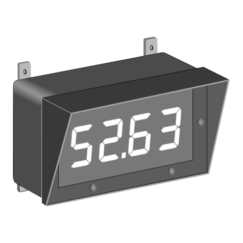
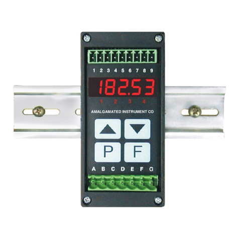
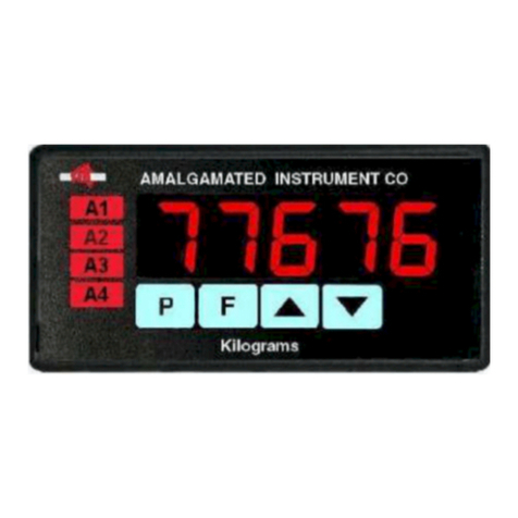
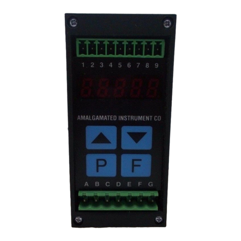
AMALGAMATED INSTRUMENT PM4-CO User manual

Model PM4-CO
Conductivity/Resistivity/ppm
DIN Rail Mount Display/Controller
Operation and Instruction Manual
AMALGAMATED INSTRUMENT CO PTY LTD ACN: 001 589 439
NSW 2077 Australia Facsimile: +61 2 9476 2902 Internet: www.aicpl.com.au

1 Introduction
This manual contains information for the installation and operation of the PM4 Conductivity
/Resistivity/ppm Monitor. The PM4-CO is a general purpose auto ranging monitor which may be
configured to accept an input from a range of conductivity cells with cell constants ranging from
K=0.01 to K=100. Ranges and typical cell factors are shown in the table below.
Cell Range Guide
Cell K uS/cm uS/m mS/cm mS/m
factor
K=0.01 0 – 125 @ 25oC 0 – 12,500 @ 25oC 0 – 0.125 @ 25oC 0 – 12.5 @ 25oC
K=0.1 0 – 1,250 @ 25oC 0 – 125,000 @ 25oC 0 – 1.25 @ 25oC 0 – 125 @ 25oC
K=1.0 10 – 12,500 @ 25oC – 0.01 – 12.5 @ 25oC 1 – 1,250 @ 25oC
K=2.0 20 – 25,000 @ 25oC – 0.02 – 25 @ 25oC 2 – 2,500 @ 25oC
K=10.0 100 – 125,000 @ 25oC – 0.1 – 125 @ 25oC 10 – 12,500 @ 25oC
K=20.0 200 – 250,000 @ 25oC – 0.2 – 250 @ 25oC 20 – 25,000 @ 25oC
A second input is provided for a temperature sensor for automatic temperature compensation.
The PM4 can accept 100Ω RTD, 1000Ω RTD, LM335 or 100Ω thermistor or UU25J1 thermistor
type temperature sensors. The default display can be set to either resistivity, conductivity, ppm
or % by weight of Sodium Chloride. The display will toggle between temperature/conductivity or
temperature/resistivity or temperature/ppm or temperature/%NaCl indication by pressing either
the ^or vbutton. The conductivity display units can be set to show either milliSiemens per
metre, milliSiemens per centimetre, microSiemens per metre or microSiemens per centimetre. The
resistivity display is in MΩ.
Calibration, setpoint and other set up functions are easily achieved by push buttons (located
at the rear panel and/or front panel depending on model). A standard inbuilt relay provides
an alarm/control function, additional relays, retransmission and DC output voltage may also be
provided. A special “blowdown” relay operation is available for units fitted with 2 relays.
Unless otherwise specified at the time of order, your PM4 has been factory set to a standard
configuration. Like all other PM4 series instruments the configuration and calibration are easily
changed by the user. Initial changes may require dismantling the instrument to alter PCB links,
other changes are made by push button functions.
Full electrical isolation between power supply, conductivity/resistivity cell and retransmission out-
put is provided by the PM4, thereby eliminating grounding and common voltage problems. This
isolation feature makes the PM4 ideal for interfacing to computers, PLCs and other data acqui-
sition devices. The single analog output option allows the choice of temperature or main display
(conductivity or resistivity, %NaCl or PPM) output. The dual analog option allows both temper-
ature and main display to be retransmitted. Analog outputs can be set for linear or logarithmic
(up to 5 decades) output. Analog output 1 can alternatively be set for PI control operation.
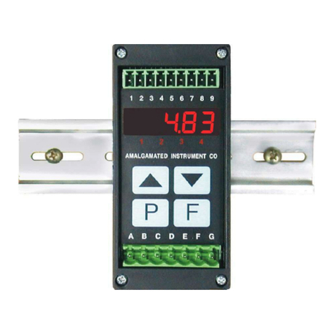
The PM4 series of Panel Mount Monitors are designed for high reliability in industrial applications.
The high brightness LED display provides good visibility, even in areas with high ambient light
levels. The high contrast LCD displays provide good visibility and are ideal for battery powered
applications. LED models are available in 4 digit (20mm), 5 digit (14.2mm) with keypad, 6 digit
(14.2mm) with keypad, and 20 segment bar graph with 5 digit (7.6mm) versions. LCD models are
available in 4 digit (12.7mm) and 6 digit (12.7mm) versions.
PM4COMAN-2.2-1 3 of 48

1.1 Output options
•1, 3 or 6 extra relays (first optional relay can be set for simple on/off alarm/control or PI
control using pulse width or frequency control)
•Isolated analog retransmission (single or dual analog outputs) configurable for 4–20mA, 0–
1V or 0–10V. Analog retransmission can be set for linear operation or logarithmic operation
using 1 to 5 decades. The first analog output is configurable for retransmission or PI control
•Isolated RS485 or RS232 serial communications (ASCII)
•Isolated Digital output - binary or BCD up to 16 bit, NPN or PNP output types available
•Optional outputs are available in certain combinations e.g. Extra relay plus RS232
1.2 Conductivity measurement general information
The instrument measures conductivity by placing an AC voltage across the two conductive surfaces
(electrodes) of the conductivity cell and measuring the resulting AC current passing through the
solution. For a given cell the AC current will increase as the conductivity of the solution increases.
Any external voltage‘s present in the solution where the cell is located may cause inaccuracy and
possibly instability in the reading. Typical sources of external voltages are level sensors and badly
earthed electrical equipment such as pumps which have contact with the solution. The amount of
AC current produced by the cell depends on the conductivity of the solution, the area of the cell
electrodes and the distance between the electrodes. Any deposits which coat the cell will reduce
the surface area available and therefore cause inaccurate readings. If cells are likely to become
coated in use they will either have to be regularly cleaned or a non contact (inductive) type cell
used. The use of non contact cells is not covered in this manual.
If resistivity, ppm or percent are selected for viewing then the instrument simply measures con-
ductivity using a conventional conductivity cell and converts this reading into the required display
units. For ppm readings the conversion factor must be manually entered.
Cell K factor - The instrument can only supply a given current range through the solution
being measured therefore a cell designed for use with pure water will not be suitable for use in
measuring very high conductivity since the instrument will not be capable of providing sufficient
current for stable measurement at both extremes. This instrument requires that the resistance
of the solution be 80Ω or higher for accurate measurement. To overcome this problem cells with
different sensitivity levels are manufactured and this sensitivity level is known as the K factor. A
cell with a higher K factor will use less current in a given solution than a cell with a lower K factor.
See the table at the beginning of this chapter for typical measuring ranges for common K factor
cells. The correct K factor cell should be chosen to suit the range required for measurement.
Temperature compensation - Since conductivity changes with temperature the conductivity
value displayed is referenced to a given temperature, usually 25oC. This means that the value
being seen on the display is not necessarily the actual conductivity of the solution at that time
but is the conductivity value which would be seen if the solution temperature was 25oC. If 25oC is
not the required reference temperature i.e. if it is required to view what the conductivity reading
would be at a different temperature then the required temperature value can be set at the SOL
"C function.
This instrument allows for either manual or automatic temperature compensation. If no tempera-
ture sensor is used with the cell then the known temperature of the solution can be entered at the
dEF "C function. If a temperature sensor is used the the reading obtained from this sensor can
4 of 48 PM4COMAN-2.2-1

be used to automatically compensate for temperature changes in the solution. For process solu-
tions whose temperature varies by more than a few degrees automatic temperature compensation
is essential for accurate readings. For example water varies its conductivity at the rate of 2%/oC.
1.3 Cell Installation
When installing conductivity cells it is important to locate the cell in a position where the pipe is
always completely full. The cell electrodes must be in complete contact with the water sample. If
air is trapped around the cell electrode it will cause errors in the measurement. If oil, grease or
any insulating material is allowed to build up on the electrode surface measurement errors will also
occur.
TBPS cells are suitable for installation into non
metallic pipework. Ideally the cell should be in-
stalled from the side of the fitting. This method
is less likely to be subjected to trapped air. The
“T” fitting should be modified to allow the face
of the cell to be flush with the inside of the fitting
or pipe wall. It is acceptable for the cell to be
slightly recessed when the cell is installed from
the side of the fitting. Alternatively a 3/4” BSP
hole may be drilled/threaded into the side of a
fitting such as an existing elbow or “T” fitting.
It is acceptable to install the cell from the top
or bottom of the pipe or fitting provided care is
taken to prevent air pockets or build up of sed-
iment. In applications where the pipe diameter
is less than 50mm the reduced sample volume
around the cell electrodes may affect the accu-
racy of the reading. In these applications in-line
calibration correction is recommended. For in-
stallation into the side wall of a tank, vessel etc.
the information above applies.
PM4COMAN-2.2-1 5 of 48

TBLR, TBTH and TBTHHT cells are suitable
for installation into metallic and non metallic
pipework. The cell measurement is made on the
inside of the cell body ensuring it is virtually
unaffected by the surrounding sample or vol-
ume. The cell may be mounted in a horizontal
or vertical position and is usually installed into
a modified “T” fitting. The cell will provide a
reliable and stable reading as long as there is a
flow through the cell. Ideally the cell should be
installed into an elbow installation with the flow
entering the cell at the base opening and exit-
ing from the holes around the perimeter. This
method will provide a fast response. Alterna-
tively the cell may be installed across the flow
(not suitable for TBLR type cells or K=10.0
TBTH cells). This will provide a stable and ac-
curate measurement, but the response time will
be slower. In most applications this will not
present a problem. These cells are also suitable
for installation into sample flow lines. These are
usually installed in a flow bypass or a sample to
waste arrangement. Sample line measurement
usually provides a slower response, but has the
advantage of allowing the cell to be removed
without disturbing the process.
6 of 48 PM4COMAN-2.2-1

2 Mechanical Installation
Choose a mounting position as far away as possible from sources of electrical noise such as motors,
generators, fluorescent lights, high voltage cables/bus bars etc. An IP65 access cover which may
be installed on the panel and surrounds is available as an option to be used when mounting the
instrument in damp/dusty positions. A wall mount case is available, as an option, for situations
in which panel mounting is either not available or not appropriate. A portable carry case is also
available, as an option, for panel mount instruments.
Prepare a panel cut out of 45mm x 92mm +1 mm / – 0 mm (see diagram below). Insert the
instrument into the cut out from the front of the panel. From the rear of the instrument fit the
two mounting brackets into the recess provided (see diagram below). Whilst holding the bracket
in place, tighten the securing screws being careful not to over-tighten, as this may damage the
instrument. Hint: use the elastic band provided to hold the mounting bracket in place whilst
tightening securing screws.
92mm
45mm PANEL CUT OUT 92mm
45mm
PANEL
CUT
OUT
115mm
104mm
53mm
44mm
96mm
9mm
9.5mm
max
48mm
91mm
111mm
10mm
Mounting bracket
(2 off)
Horizontal mounting
Vertical mounting
(bar graph displays)
PM4COMAN-2.2-1 7 of 48

3 Electrical installation
3.1 Electrical installation
The PM4 Panel Meter is designed for continuous operation and no power switch is fitted to the
unit. It is recommended that an external switch and fuse be provided to allow the unit to be
removed for servicing.
The plug in, screw type, terminal blocks allow for wires of up to 2.5mm2to be fitted. Connect the
wires to the appropriate terminals as indicated below. Refer to connection details provided in this
chapter to confirm proper selection of voltage, polarity and input type before applying power to
the instrument.
When power is applied the instrument will cycle through a display sequence indicating the software
version and other status information, this indicates that the instrument is functioning. Acknowl-
edgement of correct operation may be obtained by applying an appropriate input to the instrument
and observing the reading. The use of screened cable is recommended for signal inputs.
For connection details of optional outputs refer to the separate “PM4 Panel Meter Optional Output
Addendum” booklet supplied when options are fitted.
Instrument label (example)
8 of 48 PM4COMAN-2.2-1

3.2 Electrical connection examples
If output options are fitted refer to the ”PM4 Panel Meter Optional Output Addendum” booklet
for connection details.
Conductivity/Resistivity/ppm Cells - The cell is connected to pins 10 and 11 at the rear of
the instrument. Terminal 10 is the input connection i.e. the current input from the cell. Terminal
11 is the output connection. If using a centre core type cell the centre core wire should be connected
to Terminal 10. Ensure that the PRbE CNSt function has been correctly set for probe type. AIC
cells with temperature compensation sensors are all wired with Red, Black, Blue and Yellow (or
White on older models) inner core cable. See the note below for details of TBPS cells without
temperature compensation sensors. The wiring connections are as below.
Cell wiring colour codes
Terminal AIC cells SDI cells
Cell in 10 Blue Black
Cell out 11 Yellow (or White) White
Temperature + 9 Red Red
Temperature - 7 Black Green
Shield 7 n/a Clear
PM4COMAN-2.2-1 9 of 48

3.3 Input Output Configuration
If you need to alter the input or output configuration link settings proceed as follows:
Remove earth screw
which passes through the
case then slide out
the printed circuit board
1. Remove the plug in terminals
from the rear of the instrument
2. Remove the 4 x self tapping screws from
the back cover then remove the back cover
by pulling it away from the instrument
3. Remove the earth screw which passes
through the underside of the case then
slide out the board or boards
4. Configure the PCB links as requred, see appropriate chapter
5. Slide PCB back into case
6. Replace the earth screw which passes through the case
7. Refit the back cover and fix with the self tapping screws
8. Plug the terminal strips back into the rear of the instrument
12 of 48 PM4COMAN-2.2-1

4 Function tables - summary of setup functions
Note: the order in which the functions appear on the display may not be exactly as shown below.
The availability and order of functions is determined by choice of function settings and options
fitted.
Functions in this first table are available in FUNC or CAL mode.
Display Function Range Default Your
record
Ref/Page
AxLo Low setpoint value for
designated alarm relay x
Any display
value or OFF
OFF See
4.1
5.1 /20
AxHi High setpoint value for
designated alarm relay x
Any display
value or OFF
OFF See
4.1
5.2 /20
AxHY Hysteresis value for the
designated alarm relay x.
0to 9999 10 See
4.1
5.3 /21
Axtt Trip time delay for the
designated alarm relay x.
0to 9999 0 See
4.1
5.4 /22
Axrt Reset time delay for the
designated alarm relay x.
0to 9999 0 See
4.1
5.5 /22
Axn.o
or
Axn.c
Alarm relay xaction to
normally open (de-energised) or
normally closed (energised)
Axn.o or
Axn.c
Axn.o See
4.1
5.6 /22
AxSP
or
Axt1
etc.
Relay operation independent
setpoint or trailing setpoint
(∗Optional)
AxSP or
Axt1 etc.
AxSP See
4.1
5.7 /23
brGt Display brightness level 1to 15 15 5.8 /23
REC_ Analog output option low
display value (∗Optional)
Any display
value
05.9 /23
REC~ Analog output option high
display value (∗Optional)
Any display
value
1000 5.10 /24
REC_
Ch2
Second analog output option
low display value (∗Optional)
Any display
value
05.11 /24
REC~
Ch2
Second analog output option
high display value (∗Optional)
Any display
value
1000 5.12 /24
bAr_ Bargraph low value Any display
value
05.13 /24
bAr~ Bargraph high value Any display
value
1000 5.14 /25
(∗Optional)—this function will only be accessible if the relevant option is fitted
14 of 48 PM4COMAN-2.2-1

Functions in this second table are available only in CAL mode or if ACCS is set to ALL
Display Function Range Default Your
record
Ref/Page
bAr
tYPE
Bargraph type for instruments
with bargraph display
bAr,S.dot,
d.dot,
C.bAR or
r.dot
bAr 5.15 /25
dGOP Digital output option mode
(∗Optional)
bcd,b.SCL,
bin or bin2
bin2 5.16 /26
dG.OP Digital output option polarity
(∗Optional)
AIo or AHi AIo 5.17 /26
bcd
Strt
Digital output option BCD start
position (∗Optional)
0,1or 2 0 5.18 /26
diG_ Digital output option low value
(∗Optional)
Any display
value
05.19 /27
diG~ Digital output option high value
(∗Optional)
Any display
value
1000 5.20 /27
drnd Display rounding 1to 5000 1 5.21 /27
dCPt Decimal point 0,0.1 etc. 05.22 /27
FLtr Digital filter 0to 8 2 5.23 /28
dOSE
PERd
Special dosing mode operation 0to 600 0 5.24 /28
"C
tYPE
Temperature sensor type NONE, 100,
1000, L335,
t100 or
25J1
NONE 5.25 /28
dEF
"C
Default temperature value 0.0 to 200.0 25.0 5.26 /29
SOL
SLPE
Solution temperature
compensation slope
-6.00 to
0.00
-2.00 5.27 /29
SOL
"C
Solution temperature
compensation reference
0.0 to 100.0 25.0 5.28 /29
PRbE
CNSt
Cell K factor 0.01, 0.05,
0.1, 0.5, 1.0,
2.0, 5.0, 10,
50 or 100
0.1 5.29 /30
H.OFF
or H.ON
Hydrogen ion compensation H.OFF or
H.ON
H.OFF 5.30 /30
Ind
PRbE
Inductive cell selection on or OFF OFF 5.31 /30
CAL
NULL
Display null calibration n/a n/a 5.32 /30
CAL1 First live input calibration
scaling point
Any display
value
n/a 5.33 /31
(∗Optional)—this function will only be accessible if the relevant option is fitted
PM4COMAN-2.2-1 15 of 48

CAL2 Second live input calibration
scaling point
Any display
value
n/a 5.34 /31
"C
NULL
Temperature null calibration n/a n/a 5.35 /31
CAL
"C
Temperature calibration n/a n/a 5.36 /31
cond
unit
Conductivity measuring units uS.cm,uS.m,
mS.cm or
mS.m
uS.cm 5.37 /31
UCAL
cond
Conductivity uncalibration n/a n/a 5.38 /32
UCAL
RESt
Resistivity uncalibration n/a n/a 5.39 /32
UCAL
ppm
ppm uncalibration n/a n/a 5.40 /32
UCAL
Pcnt
Percentage uncalibration n/a n/a 5.41 /32
UCAL
"C
Temperature uncalibration n/a n/a 5.42 /33
PPm
FACt
ppm conversion factor 0.200 to
2.000
0.560 5.43 /33
SEt
dISP
Set display type cond, RESt,
PPm or Pcnt
cond 5.44 /33
rec
ctrI
Analog output PI control
(∗Optional)
on or OFF OFF 5.45 /33
Pbut Pbutton function (for
instruments with front P
button)
NONE, Hi,
Lo, HiLo,
tARE, ZERO,
P.SEt
NONE 5.46 /34
ACCS Access mode OFF, EASY,
NONE or ALL
OFF 5.47 /34
SPAC Setpoint access mode
(∗Optional)
A1, A1-2 etc. A1 5.48 /34
A1, A2
etc.
Alarm relay operation mode cond, RESt,
PPM, Pcnt,
"C or dOSE
cond See
4.1
5.49 /35
bAR Bargraph display mode
(∗Optional)
cond, RESt,
PPM, Pcnt or
"C
cond 5.50 /35
REC Analog output mode
(∗Optional)
cond, RESt,
PPM, Pcnt or
"C
cond 5.51 /36
(∗Optional)—this function will only be accessible if the relevant option is fitted
16 of 48 PM4COMAN-2.2-1

REC2 Second analog output mode
(∗Optional)
cond, RESt,
PPM, Pcnt or
"C
cond 5.52 /36
REC Analog output logarithmic or
linear mode (∗Optional)
Lin, Log1,
Log2, Log3,
Log4 or
Log5
Lin 5.53 /37
REC
Lo
Analog output logarithmic start
point (∗Optional)
0.001, 0.01,
0.1, 1.0 or
10.0
0.001 5.54 /37
REC2 Second analog output
logarithmic or linear mode
(∗Optional)
Lin, Log1,
Log2, Log3,
Log4 or
Log5
Lin 5.55 /38
REC2
Lo
Second analog output
logarithmic start point
(∗Optional)
0.001, 0.01,
0.1, 1.0 or
10.0
0.001 5.56 /38
bAUd
RAtE
Baud rate for serial
communications (∗Optional)
300, 600,
1200, 2400,
4800, 9600,
19.2 or 38.4
9600 5.57 /38
PrtY Parity for serial communications
(∗Optional)
NONE, EUEN
or odd
NONE 5.58 /38
O.Put Output for serial
communications (∗Optional)
dISP, Cont,
POLL,A.buS
or M.buS
Cont 5.59 /39
Addr Instrument address for serial
communications (∗Optional)
0to 31 0 5.60 /39
(∗Optional)—this function will only be accessible if the relevant option is fitted
4.1 Relay table
Record your relay settings in the table below
Display Relay 1 Relay 2 Relay 3 Relay 4 Relay 5 Relay 6 Relay 7
AxLo
AxHi
AxHY
Axtt
Axrt
Axn.o or Axn.c
AxSP or Axt1 etc. n/a
A1, A2 etc.
PM4COMAN-2.2-1 17 of 48

5 Explanation of functions
The PM4 setup and calibration functions are configured through a push button sequence. The
three push buttons located at the rear of the instrument (also at the front on some display options)
are used to alter settings. Two basic access modes are available:
FUNC mode (simple push button sequence) allows access to commonly set up functions such as
alarm setpoints.
CAL mode (power up sequence plus push button sequence) allows access to all functions including
calibration parameters.
Once CAL or FUNC mode has been entered you can step through the functions, by pressing and
releasing the Fpush button, until the required function is reached. Changes to functions are made
by pressing the or push button (in some cases both simultaneously) when the required function is
reached. See the flow chart example on the following page.
P F
P F P F
P F
P F
Entering ModeCAL Entering ModeFUNC
1. Remove power from
the instrument. Hold in the
button and reapply power.
The display will briefly indicate
as part of the
"wake up messages" when
the message is seen
you can release the
button. Move to step 2 below.
2. When the "wake up"
messages have finished
and the display has settled
down to its normal reading
press, then release the
button.
Move to step 3 below.
1. When the "wake up"
messages have finished
and the display has settled
down to its normal reading
press, then release the
button.
3. Within 2 seconds of
releasing the button
press, then release
the and buttons
together. The display will
now indicate followed
by the first function.
2. Within 2 seconds of
releasing the button
press, then release
the and buttons
together. The display will
now indicate followed
by the first function.
^
^
^^
FUNC
FUNC
F
F
F
FF
CAL
CAL
Note: If step 1 above has been completed then the
instrument will remain in this mode state until
power is removed. i.e. there is no need to repeat step 1
when accessing function unless power has been removed.
CAL
No special power up procedure
is required to enter mode.FUNC
18 of 48 PM4COMAN-2.2-1

Example: Entering FUNC mode to change alarm 1 high function A1Hi from OFF to 100
F U N C
F U N C End
A1Hi OFF
100
Press & release
Press & release Press & release
Press & release
Press & release F
^until
FP For until
Funtil
then press ^v
Example: Entering CAL mode to change decimal point function dCPt from 0to 0.02
F U N C
F U N C End
dCPt
CAL
0
.0 0 2
Press & release
Press & release Press & release
Press & release
Press & hold Release
Hold
Press & release F
^until
FP For until
Funtil
FF
Funtil
then press ^v
Switch off
instrument
Switch on
instrument
Easy alarm relay adjustment access facility
The display has an easy alarm access facility which allows access to the alarm setpoints simply by
pressing the Fbutton at the front or rear of the instrument. The first setpoint will then appear
and changes to this setpoint may be made to this setpoint via the ^or vbuttons. Press the
Fbutton to accept any changes or to move on to the next setpoint. Note: this easy access also
functions in the same manner for the PI control setpoint (relay and/or analog PI output) if PI
control is available. The instrument must be set in the manner described below to allow the easy
access facility to work:
1. The R.INP function must be set to SPAC or the ACCS function must be set to EASY.
2. At least one alarm must have a setpoint, nothing will happen if all the alarm setpoints are
set to OFF.
3. The SPAC function must be set to allow access to the relays required e.g. if set to A1-2
then the easy access will work only with alarm relays 1 and 2 even if more relays are fitted.
4. The instrument must be in normal measure mode i.e. if the instrument is powered up so that
it is in CAL mode then the easy access will not function. If in doubt remove power from the
instrument, wait for a few seconds then apply power again.
5. If the easy access facility is used then the only way to view or alter any other function
settings is to power up via CAL mode i.e. there is no entry to FUNC mode functions unless
the instrument is powered up in CAL mode.
PM4COMAN-2.2-1 19 of 48

Explanation of Functions
5.1 Alarm relay low setpoint
Display: AxLo
Range: Any display value or OFF
Default Value: OFF
Displays and sets the low setpoint value for the designated alarm relay x. Note xwill be replaced
by the relay number when displayed e.g. A1Lo for relay 1. Use this low setpoint function if a
relay operation is required when the display value becomes equal to or less than the low setpoint
value. To set a low alarm value go to the AxLo function and use the ^or vpush buttons to set
the value required then press Fto accept this value. The low alarm setpoint may be disabled by
pressing the ^and vpush buttons simultaneously. When the alarm is disabled the display will
indicate OFF. If the relay is allocated both a low and high setpoint then the relay will activate
when the value displayed moves outside the band set by the low and high setpoints. The value at
which the relay will reset is controlled by the AxHY function.
Example:
If A1Lo is set to 10 then relay 1 will activate when the display value is 10 or less.
Display Value
Time
A Lox
A HYxvalue
A Lo
A HY
x
x
plus
Relay
activates
at this value
or below
Relay
resets
above this
value
Alarm low operation with hysteresis
5.2 Alarm relay high setpoint
Display: AxHi
Range: Any display value or OFF
Default Value: OFF
Displays and sets the high setpoint value for the designated alarm relay x. Note xwill be replaced
by the relay number when displayed e.g. A1Hi for relay 1. Use this high setpoint function if a
relay operation is required when the display value becomes equal to or more than the low setpoint
value. To set a high alarm value go to the AxHi function and use the ^or vpush buttons to
set the value required then press Fto accept this value. The high alarm setpoint may be disabled
by pressing the ^and vpush buttons simultaneously. When the alarm is disabled the display
will indicate OFF. If the relay is allocated both a low and high setpoint then the relay will activate
when the value displayed moves outside the band set by the low and high setpoints. The value at
which the relay will reset is controlled by the AxHY function.
20 of 48 PM4COMAN-2.2-1
Table of contents
Other AMALGAMATED INSTRUMENT Controllers manuals

AMALGAMATED INSTRUMENT
AMALGAMATED INSTRUMENT PM4-RT8 Guide

AMALGAMATED INSTRUMENT
AMALGAMATED INSTRUMENT PM5-TR Guide

AMALGAMATED INSTRUMENT
AMALGAMATED INSTRUMENT PM5-TMR Guide

AMALGAMATED INSTRUMENT
AMALGAMATED INSTRUMENT RM4-LN Administrator Guide

AMALGAMATED INSTRUMENT
AMALGAMATED INSTRUMENT PM4-IV User manual

AMALGAMATED INSTRUMENT
AMALGAMATED INSTRUMENT RM4-IV Guide

AMALGAMATED INSTRUMENT
AMALGAMATED INSTRUMENT PM4-IVT Guide

AMALGAMATED INSTRUMENT
AMALGAMATED INSTRUMENT RM4-AV Guide

AMALGAMATED INSTRUMENT
AMALGAMATED INSTRUMENT LD4-LN Guide

AMALGAMATED INSTRUMENT
AMALGAMATED INSTRUMENT RM4-AI Guide