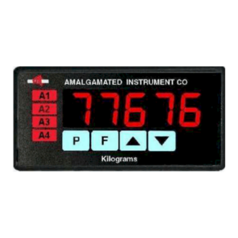
AMALGAMATED INSTRUMENT LD4-LN Guide

LD4-LN
Large Digit Display
DC Current / DC Voltage
50 Point Lineariser
Operation and Instruction Manual
(Inputs 0-20mA, 4-20mA, 0-100mV,
0-1V, 0-10V or 0-100V)
ACN: 001 589 439
AMALGAMATED INSTRUMENT CO PTY LTD
Unit 5, 28 Leighton Place Hornsby Telephone:
NSW 2077 AUSTRALIA Facsimile:
+61 2 9476 2902 Internet: www.aicpl.com.au

Table of Contents
Introduction . . . . . . . . . . . . . . . . . . . . . . . . . . . . . . . . . . . . 3
Mechanical Installation. . . . . . . . . . . . . . . . . . . . . . . . . . . . . . 4
Electrical Installation . . . . . . . . . . . . . . . . . . . . . . . . . . . . . . . 5
Power supply connections . . . . . . . . . . . . . . . . . . . . . . . . . . . 6
Relay connections . . . . . . . . . . . . . . . . . . . . . . . . . . . . . . . 6
Input/output connectors . . . . . . . . . . . . . . . . . . . . . . . . . . . . . 7
Input type selector links . . . . . . . . . . . . . . . . . . . . . . . . . . . . . 9
Remote input connector. . . . . . . . . . . . . . . . . . . . . . . . . . . . . 9
Explanation of Functions . . . . . . . . . . . . . . . . . . . . . . . . . . . . 10
Calibration functions. . . . . . . . . . . . . . . . . . . . . . . . . . . . . . 15
Lineariser functions . . . . . . . . . . . . . . . . . . . . . . . . . . . . . . 19
Error Messages . . . . . . . . . . . . . . . . . . . . . . . . . . . . . . . . 25
Function Table. . . . . . . . . . . . . . . . . . . . . . . . . . . . . . . . . . 26
Lineariser table . . . . . . . . . . . . . . . . . . . . . . . . . . . . . . . . . 28
Analog PI Control Output . . . . . . . . . . . . . . . . . . . . . . . . . . . . 29
Proportional control output. . . . . . . . . . . . . . . . . . . . . . . . . . . 29
Integral control output . . . . . . . . . . . . . . . . . . . . . . . . . . . . . 31
Specifications . . . . . . . . . . . . . . . . . . . . . . . . . . . . . . . . . . 34
Technical Specifications . . . . . . . . . . . . . . . . . . . . . . . . . . . . 34
Options . . . . . . . . . . . . . . . . . . . . . . . . . . . . . . . . . . . . 34
Physical characteristics . . . . . . . . . . . . . . . . . . . . . . . . . . . . 34
Guarantee and Service . . . . . . . . . . . . . . . . . . . . . . . . . . . . . 35
Optional outputs . . . . . . . . . . . . . . . . . . . . . . . . . . . . . . . . 36
Serial communications option . . . . . . . . . . . . . . . . . . . . . . . . . 36
Modbus communications . . . . . . . . . . . . . . . . . . . . . . . . . . . 42
Analog retransmission option . . . . . . . . . . . . . . . . . . . . . . . . . 45
Relay 3 and 4 option. . . . . . . . . . . . . . . . . . . . . . . . . . . . . . 46
EL01 22H03 Page 2 of 46 LD4LNMAN-1.0-1

1 Introduction
This manual contains information for the installation and operation of the LD4-LN Lineariser
Monitor.The LD4 is a general purpose instrument which may be configured to accept an input of 0 to 20mA, 4
to 20mA, ±100mV, ±1V, ±10V or ±100VDC. The LD4-LN offers the choice of linear, square root or linearised
display.
In lineariser operation up to 50 points may be entered. These points and any function settings and
scaling values are stored in EEPROM memory. The lineariser points are stored in a “lineariser table”. A
written copy of the table should be maintained for reference, a table is provided in for this purpose. The
lineariser table stores the display values for each point and the input values (scaled or otherwise) associated
with these display values. Prior to entering values into the table the display must be scaled via a 2 point
calibration. Functions CAL1 and CAL2 can be used for live input display scaling for all input types. For
4-20mA inputs only an alternative scaling method is provided via the USER En4 and USER En20
functions. The ^and vbuttons on the main circuit board can be used to toggle between then linearised
(Linr) and linear input (INPt) values.
Two separate sets of calibration scaling values can be stored, with the display choice being made
via a remote input.
Two standard inbuilt relays are provided for alarm/control functions, a transmitter supply of 18VDC
(unregulated) is also provided on AC powered models. An optional isolated ±12V (24V) transmitter supply is
available. Optional isolated analog retransmission or serial communications or two extra relays may also be
optionally provided.
Unless otherwise specified at the time of order, your LD4 has been factory set to a standard
configuration, see the “Function Table” for a list of default settings. Like all other LD4 series instruments the
configuration and calibration is easily changed by the user. Initial changes may require dismantling the
instrument to alter PCB links, other changes are made via push button functions.
The LD4 series of Large Digit Display Monitors are designed for high reliability in industrial
applications. The high brightness LED display provides good visibility, even in areas with high ambient light
levels.
Page 3 of 46 LD4LNMAN-1.0-1
5@63
Programming keypad (on main circuit board)
Power supply 240VAC, 110VAC, 12 to 16VAC, 15 to 24VDC or
optional isolated DC supplies (factory configured)
Signal input ±20mA, 4-20mA, ±100mV, ±1V, ±10V or ±100V (set via internal links)
Remote switch input to perform special functions
Inputs
Standard outputs
Optional outputs
Two alarm relays
Transmitter supply 16VDC unregulated & non isolated (AC powered models only)
Two extra alarm relays
Analog retransmission 4-20mA, 0-1V or 0-10V
Serial communications RS232 or RS485 ASCII
Isolated & regulated transmitter supply 24VDC (±12V)

2 Mechanical Installation
The instrument is designed be wall mounted. Carefully measure and drill holes, as shown below.
All sizes are in mm. Mounting hole diameters are 6.5mm.
Page 4 of 46 LD4LNMAN-1.0-1
5@63
180
155
121
85
145
253
57mm 4 digit display
An optional panel mount kit is available for
the 57mm type display. Panel cut out size is
240 x 130mm
(-0.0mm/+0.5mm)
155mm
180mm
Model LD4-XX-XXX-574
Mounting hole dimensions

3 Electrical Installation
The LD4-LN instrument is designed for continuous operation and no power switch is fitted to the
unit. It is recommended that an external switch and fuse be provided to allow the unit to be removed for
servicing.
The terminal blocks, which are the plug in type for ease of installation, allow for wires of up to
1.5mm2(2.5mm2for relay and power connections) to be fitted. Connect the wires to the appropriate
terminals as indicated below. Refer to other details provided in this manual to confirm proper selection of
voltage, polarity and input type before applying power to the instrument. When power is applied the
instrument will cycle through a display sequence, indicating the software version and other status
information, this indicates that the instrument is functioning.
See the appropriate appendix at the rear of this manual for option board electrical connections.
MAIN CIRCUIT BOARD LAYOUT (PARTIAL VIEW)
Page 5 of 46 LD4LNMAN-1.0-1
PF
GND
LK11
LK1
X10
REF
P8
LK10
LK2
POWER
IN
RELAY 1
RELAY 2
P1
VOLTS
4-20mA
-
-
UN
REG COM
INPUT EXCITATION
++
REMOTE
IN
P F
GND +
MAX 24V
INPUT/OUTPUT
CONNECTORS
EXTERNAL
PUSH BUTTON
CONNECTOR
INPUT LINKS LOW VOLTAGE
POWER SUPPLY
CONNECTOR
DISPLAY
BOARD
CONNECTOR
OPTIONAL
OUTPUT BOARD
CONNECTOR
P7
REMOTE INPUT
CONNECTOR
OPTIONAL
INPUT BOARD
CONNECTOR
P3
SETUP PUSH
BUTTONS
INPUT SCALING
LINKS
RELAY
CONNECTORS

3 .1 Power supply connections
Mains power connections (240VAC or 110VAC) are made via a plug in terminal with screw
connections.
The transformer low voltage AC output goes to the power supply connector P1 on the main circuit
board via the lead supplied.
Non isolated DC supplies (15 to 24V) are connected at the main circuit board power supply
connector P1 via the plug in connector terminals. The positive and negative supplies may be connected
either way around.
Optional isolated DC supplies use plug in terminals supplied on the power supply board as shown
below. The output from the isolated DC supply board connects directly to the main circuit board power supply
connector via the plug in connector (P1) terminals.
3 .2 Relay connections
The LD4 is supplied with two alarm relays as standard with connections on P6.The relays are single
pole, single throw types and are rated at 5A, 240VAC into a resistive load. The relay contact is voltage free
and may be programmed for normally open or normally closed operation.
Page 6 of 46 LD4LNMAN-1.0-1
AC MAINS
ENA
AC OUT
LARGE DIGIT POWER SUPPLY
SERIAL NO.
TRANSFORMER
SOCKET FOR 240/110V
PLUG IN MAINS
CONNECTOR
TRANSFORMER
AC OUTPUT
SOCKET
DC INPUT
E
-
+
DC OUT
LARGE DIGIT POWER SUPPLY
SERIAL NO.
DC TO DC
CONVERTER
(ISOLATING)
SOCKET FOR DC
INPUT CONNECTOR
SOCKET FOR DC
OUTPUT CONNECTOR
FOR DC SUPPLY TO
LD4 INPUT CIRCUIT BOARD
-
+
OPTIONAL ISOLATED DC BOARD

3 .3 Input/output connectors
The diagram shows the input/output connectors for the LD4-LN. The
input signal connection is between INPUT + and INPUT -. The standard 18VDC
unregulated transmitter supply output is between INPUT - and EXCITATION UN
REG. The optional 24VDC (±12V) transmitter supply output is between COM,
EXCITATION + and EXCITATION -. Wires of up to 1.5mm diameter can be
accepted. The connectors are of the plug in type for ease of installation.
Connection examples
1. 4 wire ±20mA or 4-20mA input - externally powered sensor
2. 3 wire ±20mA or 4-20mA input - externally powered sensor, common negative
3. 2 wire ±20mA or 4-20mA input - externally powered sensor
Page 7 of 46 LD4LNMAN-1.0-1
-
-
UN
REG COM
INPUT EXCITATION
++
PLUG IN
AFTER
WIRING
INPUT
+
+
+
-
-
-
18VDC
UNREGULATED
TRANSMITTER
SUPPLY
COM
OPTIONAL
TRANSMITTER
SUPPLY
-
-
UN
REG COM
INPUT EXCITATION
++
PLUG IN
AFTER WIRING
SENSOR
External Power
Input
+
+
-
-
Shield
-
-
UN
REG COM
INPUT EXCITATION
++
SENSOR
External Power
Input
+
+
-
-
PLUG IN
AFTER WIRING
S
hield
-
-
UN
REG COM
INPUT EXCITATION
++
SENSOR
External Power
Input
+
+
-
-
PLUG IN
AFTER WIRING
Shield

4. 2 wire 4-20mA input - powered from standard 18VDC supply (AC powered models only)
5. 3 wire ±20mA or 4-20mA input - powered from standard 18VDC supply (AC powered models only)
6. 2 wire ±20mA or 4-20mA input - powered from optional 24V (±12V) supply
7. 3 wire ±20mA or 4-20mA input - powered from optional 24V (±12V) supply
Page 8 of 46 LD4LNMAN-1.0-1
SENSOR
+
-
-
-
UN
REG COM
INPUT EXCITATION
++
PLUG IN
AFTER WIRING
Shield
-
-
UN
REG COM
INPUT EXCITATION
++
SENSOR
+
-
PLUG IN
AFTER WIRING
S
hield
Supply
Output
-
-
UN
REG COM
INPUT EXCITATION
++
SENSOR
+
-
PLUG IN
AFTER WIRING
S
hield
Supply
Output
Link
-
-
UN
REG COM
INPUT EXCITATION
++
SENSOR
+
-
Link
PLUG IN
AFTER WIRING
Shield

8. DC voltage input - powered from optional supply using +12V
3 .4 Input type selector links
The input type selector links must be set to suit the input type required. Input links allow selection of
4-20mA, 0-1VDC, 0-10VDC or 0-100VDC input. Note that the x10 link (LK11) is used for the 0-100mVDC
input range. The 4-20mA input will allow both 4-20mA and 0-20mA input ranges. Note: Input link LK1 must
always be in unless an optional input board is fitted.
3 .5 Remote input connector
The LD4-LN has a software function named R.INP or remote input.
Closure of the remote input connector via a switch or relay contact will cause
the selected remote input function to operate. Choose the switch type to suit
the remote input required e.g. for a ZERO function a momentary action switch
is most commonly used, for a display hold dHLd a latching switch may be
required.
Page 9 of 46 LD4LNMAN-1.0-1
REMOTE
IN
GND +
PLUG IN
AFTER
WIRING
LATCHING OR
MOMENTARY
ACTION SWITCH
LK11
LK11
LK11
LK11
LK11
X10
X10
X1
0
X10
X10
LK10
100V 100V100V 100V 100V
10V 10V10V 10V 10V
1V 1V1V 1V 1V
LK2
VOLTS
4-20mA
LK10
LK2
VOLTS
4-20mA
LK10
LK2
VOLTS
4-20mA
LK10
LK2
VOLTS
4-20mA
LK10
LK2
VOLTS
4-20mA
4-20mA or
0-20mA
Input
0-100mV
Input
0-1V
Input
0-10V
Input
0-100V
Input
SENSOR
+
-
-
-
UN
REG COM
INPUT EXCITATION
++
PLUG IN
AFTER WIRING
Shield
+
-
Supply

4 Explanation of Functions
The LD4 setup and calibration functions are configured through a push button sequence.Two levels
of access are provided for setting up and calibrating:-
FUNC mode (simple push button sequence) allows access to commonly set up functions such as
alarm setpoints.
CAL mode (power up sequence plus push button sequence) allows access to all functions including
calibration parameters.
The three push buttons located on the main circuit board are used to alter settings. Once CAL or
FUNC mode has been entered you can step through the functions, by pressing and releasing the Fpush
button, until the required function is reached. Changes to functions are made by pressing the ^or vpush
button (in some cases both simultaneously) when the required function is reached. See the flow chart
example which follows
Page 10 of 46 LD4LNMAN-1.0-1
F
FF
FF
Entering ModeCAL Entering ModeFUNC
1. Remove power from the instrument
and wait 5 seconds . Hold in the
button and reapply power.
The display will indicate
as part of the
"wake up messages" when
the message is seen
you can release the
button.
Move to step 2 below.
2. When the "wake up"
messages have finished
and the display has settled
down to its normal reading
press, then release the
button.
Move to step 3 below.
1. When the "wake up"
messages have finished
and the display has settled
down to its normal reading
press, then release the
button.
Move to step 2 below.
3. Within 2 seconds of
releasing the button
press, then release
the and buttons
together. The display will
now indicate followed
by the first function.
2. Within 2 seconds of
releasing the button
press, then release
the and buttons
together. The display will
now indicate followed
by the first function.
^
^
^^
FUNC
FUNC
F
F
F
FF
CAL
CAL
Notes: If step 1 above has been completed then the
instrument will remain in this mode state until
power is removed. i.e. there is no need to repeat step 1
when accessing function unless power has been removed.
The instrument should show all 8’s on power up
e.g. if the instrument does not reset then
these numbers will not be seen. Switch off the instrument
and allow a lon
g
er time delay before powerin
g
up a
g
ain.
CAL
8.8.8.8.
No special power up procedure
is required to enter mode.FUNC

The alarm and brightness functions below are accessible via FUNC mode.
The LD4-LN has an easy alarm access facility which allows access to the alarm setpoints simply by
pressing the Fbutton. The first setpoint will then appear and changes to this setpoint may be made to this
setpoint via the ^or vbuttons. Press the Fbutton to accept any changes or to move on to the next
setpoint.
The instrument must be set in the manner described below to allow the easy access facility to work:
1. The R.INP function must be set to SP.AC or the ACCS function must be set to EASY.
2. At least one alarm must have a setpoint, nothing will happen if all the alarm setpoints are set to OFF.
3. The SP.AC function must be set to allow access to the relays required e.g. if set to A1-2 then the
easy access will work only with alarm relays 1 and 2 even if more relays are fitted.
4. The instrument must be in normal measure mode i.e. if the instrument is powered up so that it is in
CAL mode then the easy access will not function. If in doubt then remove power from the instrument,
wait for a few seconds then apply power again.
5. If the easy access facility is used then the only way to view or alter any other function settings is to
power up via CAL mode i.e. there is not entry to FUNC mode unless the instrument is powered up in
CAL mode.
See the "Analog PI Control Output" chapter for an explanation of the analog PI control functions
available when the optional analog output is fitted.
A1Lo (alarm low setpoint)
Displays and sets the low setpoint value for alarm 1 relay.The low alarm setpoint may be disabled by
pressing the ^and vpushbuttons simultaneously.When the alarm is disabled the display will indicate OFF
.Use^or vto adjust the setpoint value if required.The alarm will activate when the displayed value is lower
than the A1Lo setpoint value. Each relay may be configured with both a low and high setpoint if required, if
so the relay will be activated when the display reading moves outside the band set between low and high
setpoints.
Page 11 of 46 LD4LNMAN-1.0-1
F U N C
F U N C
F U N C
F U N C
End
End
A1Hi
dCPt
CAL
OFF
0
100
.0 0 2
Press & release
Press & release
Press & release
Press & release
Press & release
Press & release
Press & release
Press & release
Press & hold Release
Hold
Press & release F
Press & release F
^until
^until
F
F
PF
or until
PFor until
Funtil
Funtil
FF
Funtil
then press ^v
then press ^v
Switch off
instrument
Switch on
instrument
Example: Entering mode to change alarm 1 high function from toFUNC A1Hi OFF 100
Example: Entering mode to change decimal point function from toCAL dCPt 0 0.02

A1Hi (alarm high setpoint)
Displays and sets the high setpoint value for alarm 1 relay. The high alarm setpoint may be disabled
by pressing the ^and vpushbuttons simultaneously. When the alarm is disabled the display will indicate
OFF.Use^or vto adjust the setpoint value if required. The alarm will activate when the displayed value is
higher than the A1Hi setpoint value. Each relay may be configured with both a low and high setpoint if
required, if so the relay will be activated when the display reading moves outside the band set between low
and high setpoints.
A1HY (alarm hysteresis [deadband])
Displays and sets the alarm hysteresis
limit and is common for both high and low
setpoint values. The hysteresis value may be
used to prevent too frequent operation of the
setpoint relay when the measured value stays
close to the setpoint. Without a hysteresis
setting (A1HY set to zero) the alarm will activate
when the display value goes above the alarm
setpoint (for high alarm) and will reset when the
display value falls below the setpoint, this can
result in repeated on/off switching of the relay at
around the setpoint value.The hysteresis setting
operates as follows:
In the high alarm mode, once the alarm
is activated the input must fall below the setpoint
value minus the hysteresis value to reset the
alarm. e.g. if A1Hi is set to 50.0 and A1Hy is
set to 3.0 then the setpoint output relay will
activate once the display value goes above
50.0 and will reset when the display value goes
below 47.0 (50.0 minus 3.0).
In the low alarm mode, once the alarm
is activated the input must rise above the
setpoint value plus the hysteresis value to reset
the alarm.
e.g.if A1Lo is set to 20.0 and A1Hy is
set to 10.0 then the alarm output relay will
activate when the display value falls below 20.0
and will reset when the display value goes above 30.0 (20.0 plus 10.0).
The hysteresis units are expressed in displayed engineering units.
A1tt (alarm trip time)
Displays and sets the alarm trip time and is common for both alarm high and low setpoint values.
The trip time is the delay time before the alarm relay will activate, or trip, when an alarm condition is present.
The alarm condition must be present continuously for the trip time period before the alarm will trip. This
function is useful for preventing an alarm trip due to short non critical deviations from setpoint. The trip time is
selectable over 0to 9999 seconds.
A1rt (alarm reset time)
Displays and sets the alarm relay reset time.With the alarm condition is removed the alarm relay will
stay in its alarm condition for the time selected as the reset time. The reset time is selectable over 0to 9999
seconds.
Page 12 of 46 LD4LNMAN-1.0-1
Display Value
Tim
e
ALox
Setpoint
relay
activates
Setpoint
relay
resets
AHYx value
(hysteresis or deadband)
Display Value
Tim
e
AHix
Setpoint
relay
activates Setpoint
relay
resets
AHYx value
(hysteresis or deadband)

A1n.o or A1n.c (alarm x normally open or normally closed)
Displays and sets the setpoint alarm relay action to normally open (de-energised) or normally
closed (energised), when no alarm condition is present. A normally closed alarm is often used to provide a
power failure alarm indication.
A2Lo, A3Lo &A4Lo (alarm low setpoint)
Displays and sets alarm 2,3&4lowsetpoints, see A1Lo for further description. Note: alarm relays
3 & 4 are only fitted as options.
A2Hi, A3Hi &A4Hi (alarm high setpoint)
Displays and sets alarm 2, 3 & 4 high setpoints, see A1Hi for further description. Note: alarm
relays 3 & 4 are only fitted as options.
A2HY, A3HY &A4 HY (alarm hysteresis [deadband])
Displays and sets the alarm hysteresis limit for alarm 2, 3 & 4, see A1HY for further description.
Note: alarm relays 3 & 4 are only fitted as options.
A2tt, A3tt &A4tt (alarm trip time)
Displays and sets the alarm trip time for alarm 2, 3 & 4, see A1tt for further description. Note:
alarm relays 3 & 4 are only fitted as options.
A2rt, A3rt &A4 rt (alarm reset time)
Displays and sets the alarm relay reset time for alarm 2, see A1rt for further description. Note:
alarm relays 3 & 4 are only fitted as options.
A2n.o /A2n.c, A3n.o/A3n.c,A4n.o/A4n.c (alarm normally open or normally closed)
Displays and sets the setpoint alarm relay action for alarm 2, 3 & 4, see A1n.o /A1n.c for further
description. Note: alarm relays 3 & 4 are only fitted as options.
Ax.SP,Ax.t1,Ax.t2 etc. (relay operation independent setpoint or trailing) - this function will not be
seen if both the high and low setpoints are set to OFF.
Each alarm may be programmed to operate with an independent setpoint setting or may be linked
(or trailing) to operate at a fixed difference to another relay setpoint. The operation is as follows: Alarm 1 (AI)
is always independent. Alarm 2 (A2) may be independent or may be linked to Alarm 1. Alarm 3 (A3)maybe
independent or may be linked to Alarm 1 or Alarm 2. Alarm 4 (A4) may be independent or may be linked to
Alarm 1, Alarm 2 or Alarm 3. The operation of each alarm is selectable within the Function Setup Mode by
selecting, for example, (Alarm 4) A4.SP = Alarm 4 normal setpoint or A4.t1 = Alarm 4 trailing Alarm 1 or
A4.t2 = Alarm 4 trailing Alarm 2 or A4.t3 = Alarm 4 trailing Alarm 3.For trailing set points the setpoint value
is entered as the difference from the setpoint being trailed.
If the trailing setpoint is to operate ahead of the prime setpoint then the value is entered as a positive
number and if operating behind the prime setpoint then the value is entered as a negative number. For
example, with Alarm 2 set to trail alarm 1, if A1Hi is set to 1000 and A2Hi is set to 50 then Alarm 1 will trip at
1000 and alarm 2 will trip at 1050 (i.e.1000 + 50). If Alarm 2 had been set at -50 then alarm 2 would trip at 950
(i.e. 1000 - 50). See the trailing alarm table which follows.
Page 13 of 46 LD4LNMAN-1.0-1
Alarm relay
contacts are
open if no alarm
condition present
Alarm relay
contacts are
closed if no alarm
condition present
Alarm relay
contacts close
during alarm
condition
Alarm relay
contacts open
during alarm
condition
Alarm normally open Alarm normally closed

Trailing Alarm Table
Showing Possible Alarm Assignments
A2 A3 A4
A1 A2.t1 A3.t1 a4.t1
A2 A3.t2 A4.t2
A3 a4.t3
brgt (display brightness)
Displays and sets the digital display brightness. The display brightness is selectable from 1to 15,
where 1= lowest intensity and 15 = highest intensity. This function is useful for improving the display
readability in dark areas or to reduce the power consumption of the instrument.
duLL (remote input controlled display brightness)
This function will not be seen unless the R.INP function is set to duLL. Displays and sets the level
for remote input brightness switching, see R.INP function. When the remote input function is set to duLL
the remote input can be used to switch between the display brightness level set by the brgt function and the
display brightness set by the duLL function. The display brightness is selectable from 0to 15, where 0=
lowest intensity and 15 = highest intensity.This function is useful in reducing glare when the display needs to
be viewed in both light and dark ambient light levels.
The functions which follow are accessible via CAL mode only.
rEC_ (recorder/analog retransmission output low value)
Seen only when analog retransmission option fitted. Displays and sets the analog retransmission
(4-20mA, 0-1V or 0-10V, link selectable) output low value (4mA or 0V) in displayed engineering units. e.g.if it
is required to retransmit 4mA when the display indicates 0then select 0in this function via the ^or v
button. This function will not be seen if the REC ctrI function is set to on.
rEC~ (recorder/analog retransmission output high value)
Seen only when analog retransmission option fitted. Displays and sets the analog retransmission
(4-20mA, 0-1V or 0-10V, link selectable) output high value (20mA, 1V or 10V) in displayed engineering units.
e.g.if it is required to retransmit 20mA when the display indicates 500 then select 500 in this function via the
^or vbutton. This function will not be seen if the REC ctrI function is set to on.
drnd (display rounding)
Displays and sets the display rounding value. This value may be set to 0 - 5000 displayed units.
Display rounding is useful for reducing the instrument resolution without loss of accuracy, in applications
where it is undesirable to display to a fine tolerance. For example if drnd is set to 10 the display indication
will change in multiples of 10 only i.e. it will be able to display 0,10, 20, 30 etc. but not 2, 4,15 etc.
dCPt (decimal point selection)
Displays and sets the decimal point. By pressing the ^or vpushbuttons the decimal point position
may be set. The display will indicate as follows: 0(no decimal point), 0.1 (1 decimal place), 0.02 (2 decimal
places) or 0.003 (3 decimal places).
FItr (digital filter)
Displays and sets the digital filter value. Digital filtering is used for reducing susceptibility to short
term interference. The digital filter range is selectable from 0to 8, where 0= none and 8= most filtering. A
typical value for the digital filter would be 3. Use ^or vto alter if required.Note that at higher filter values the
display update time will be increased.
REC ctrI (Analog output mode)
Seen only when analog output option is fitted.Refer to the "Analog PI Control Output" chapter for an
explanation of the analog PI control functions available when the optional analog output is fitted.
This function allows selection of on or OFF for PI control analog output. If set to OFF the analog
output operates as a retransmission output and uses the functions described in this chapter. If set to on the
analog output operates as a PI control output.
Page 14 of 46 LD4LNMAN-1.0-1

4 .1 Calibration functions.
The CAL 1 and CAL 2 functions described below allow the display to be scaled to read in engineering units
using “live” inputs. For 4-20mA inputs and alternative method which does not require “live” inputs may be
used, see the UsER En4 and USER En20 functions which follow.
CAL1 (first scaling point for 2 point scaling method)
CAL1 and CAL2 are used together to scale the instruments display, values for both must be set
when using this scaling method.
The CAL1 function sets the first calibration point for live input calibration . When using this method
a “live” signal input must be present at the input terminals. Note: CAL1 and CAL2 can be set independently
i.e. it is not necessary to perform a CAL2 operation directly after a CAL1.
The procedure for entering the first scaling point is:
a. Ensure that an input signal is present at the input terminals, this will normally be at the low end of the
signal range e.g. 4mA for a 4-20mA input type.
b. At the CAL1 function press ^and vsimultaneously, then release them. The display will indicate
the live input value. Do not be concerned at this stage if the live input display value is not what is
required. It is important that the live input value seen is a steady value, if not then the input stability
needs to be investigated before proceeding with the scaling.
c. Press, then release the Fbutton. The display will indicate SCL1 followed by a value. Use the ^or
vbutton to change this value to the required display scale value at this input. e.g. if 4mA was input and
the required display at 4mA was 0then ensure 0is selected at SCL1. Press the Fbutton to accept
changes, the display will show CAL End and will then move on to the next function.
CAL2 (second scaling point for 2 point scaling method)
The second point scaling is performed in exactly the same manner as CAL1 except that SCL2 will
be seen instead of SCL1. It is essential that the live input is different in value to the CAL1 input e.g. for a
4-20mA input use 20mA as the CAL2 live input. Note; it is not essential that exactly 4 and 20mA are used as
the live inputs for a 4-20mA scaling but the input values must be significantly different.
The procedure for entering the second scaling point is:
a. Ensure that an input signal (different to the input used at CAL1) is present at the input terminals, this
will normally be at the high end of the signal range e.g. 20mA for a 4-20mA input type.
b. At the CAL2 function press ^and vsimultaneously, then release them. The display will indicate
the live input value. Do not be concerned at this stage if the live input display value is not what is
required. It is important that the live input value seen is a steady value, if not then the input stability
needs to be investigated before proceeding with the scaling.
c. Press, then release the Fbutton. The display will indicate SCL2 followed by a value. Use the ^or
vbutton to change this value to the required display scale value at this input. e.g. if 20mA was input
and the required display at 20mA was 500 then ensure 500 is selected at SCL2. Press the Fbutton
to accept changes, the display will show CAL End and will then move on to the next function.
Page 15 of 46 LD4LNMAN-1.0-1
Input
Input
Display value
Display value
CAL2
CAL2
CAL1
SCL1
CAL1
SCL2
Setting CAL1 Setting CAL2

CAL OFSt (calibration offset)
The calibration offset is a single point adjustment which
can be used to alter the calibration scaling values across the
entire measuring range without affecting the calibration slope.
This method can be used instead of performing a two point
calibration when a constant measurement error is found to exist
across the entire range. To perform a calibration offset press the
^and vbuttons simultaneously at the CAL OFSt function. A
"live" reading from the input will be seen, make a note of this
reading. Press the Fbutton, the message SCLE will now be
seen followed by the last scale value in memory. Use the ^or v
button to adjust the scale value to the required display value for
that input. For example if the "live" input reading was 50 and the
required display value for this input was 70 then adjust the SCLE
value to 70.
Page 16 of 46 LD4LNMAN-1.0-1
Example - Scaling using two live inputs
Enter via mode,
see page 11
CAL
Place at the input a low level
signal for which the required
scaling value is known e.g. 4mA
Go to the function
and press and
simultaneously a "live"
display will now be seen
CAL1
^v
If the "live" display is stable
press the button. The
message will be seen
F
SCL1
If the "live" display is stable
press the button. The
message will be seen
F
SCL2
Use the or button to
enter the required scale
value for the input then press
to accept the new scaling value
^v
F
Use the or button to
enter the required scale value
for the second input then press
and release to accept the
new scaling value
^v
F
Press and release until the
function is reached.
Press and simultaneously.
A "live" reading will be seen,
adjust the input until the live
reading is zero. Press . The
display should now show
F
F
CAL ZERO
CAL ZERO End
^v
Press and release until
the message
is seen and the display
returns to normal measurement
FUNC End
F
The message will be seen.
Increase the input signal then
press and simultaneously.
Ideally the second input should be
as close to 100% of range as
possible e.g. 20mA. A "live"
display will now be seen
CAL2
^v
Note: If the "live" display at any scaling
point is not stable then check the input
signal for stability.
This step
required only if
the button or
remote input
function
is to be used.
P
ZERO
Input
Display value
offse
t
offset

ZERO RNGE (zero range)
The zero range function allows a limit value to be set (in engineering units) above which the display
will not zero i.e. if a zero operation is attempted via the Pbutton, remote input or set zero function when the
display value is greater than the zero range setting the display will refuse to zero and give a ZERORNGEErr
message (note that the CAL OFSt function is also affected by the ZERO RNGE setting). For example if the
zero range setting is 10 the instrument will only respond to a zero operation if the display reading at the time is
between -10 and 10. If the zero range function is not required it can be set to OFF by pressing the ^and v
buttons simultaneously at this function. When switched off the instrument can be zeroed no matter what the
display value.
Note that the instrument keeps track of the value being zeroed at each operation, when the total
amount zeroed from repeated operations becomes greater than the zero range value the instrument will
reject the zero operation and a ZERO RNGE Err message will be seen. To allow a zero operation beyond
this point either the ZERO RNGE function value will need to be raised or a new zero reference point
introduced via the CAL ZERO function.
If repeated zero operations are required the ZERO RNGE function should be set to OFF or
alternatively the tARE operation could be considered.
CAL ZERO (calibration zero)
The calibration zero function is used following a calibration via CAL1 and CAL2. A calibration zero
operation at this time ensures that the display zero and the ZERO RNGE reference zero are at the same
point after a calibration. After a calibration the calibration zero can also be used to select a zero point other
than the display zero as the reference for the ZERO RNGE function. For example if the CAL ZERO operation
is carried out with a display reading of 500 and a ZERO RNGEreading of 10 the zero range function will allow
the display to zero only if the current display reading is between 490 and 510. To perform a calibration zero
press the ^and vbuttons simultaneously at the CAL ZERO function, a live reading will be seen, press the
Fbutton, the message CAL ZERO End should now be seen indicating that the instrument has accepted
the zero point. Although the display reading will not change as a result of the calibration zero the input value
on the display at the time of the operation will be the new zero reference point for the ZERO RNGE function.
USEREn4(4mA input scaling without a live input)
This calibration method can be used with 4-20mA inputs only. The instrument can be scaled for a
4-20mA input without a live input i.e. this is an alternative method to the CAL1 and CAL2 method of scaling.
To perform the first point (En 4) scaling simply press the ^and vbuttons simultaneously when the USER
En 4 function has been reached. The display will now indicate a value. Use the ^or vbutton to change this
value to the scale value required for a 4mA input. Once the USER En 4 scaling has been completed, the
USER En20 function should be completed, see below.
USER En20 (20mA input scaling without a live input)
This calibration method can be used with 4-20mA inputs only.The same method described in USER
En4 above can be used to scale the instrument for a 20mA input.Again use the ^or vbutton to change the
value displayed to the scale value required for a 20mA input.
Example:If the 4-20mA input is to be scaled so that the display reads 0at 4mA and 5000 at 20mA
then USER En4 should be set to 0and USER En20 should be set to 5000.
UCAL (uncalibrate)
Used to set the instrument back to the factory calibration values. This function should only be used
when calibration problems exist, and it is necessary to clear the calibration memory. To reset the instrument
calibration press ^and vtogether at the UCAL function. The message CAL CLr should be seen.
Page 17 of 46 LD4LNMAN-1.0-1

P.but (Pbutton function)
The Pbutton may be set to operate some of the remote input functions, see R.INP below for a
description of these functions. If both the remote input and Pbutton function are operated simultaneously
the Pbutton will override the remote input. The functions below are as described in the R.INP function
above with the exception of the P.SEt function.
Functions available are:
NONE,Hi,Lo ,HiLo,tARE or ZERO
Note:To prevent accidental operation of the Pbutton in the tArE orZEROfunctions it is necessary
to hold the button in for 2 seconds to perform the selected operation.
R.INP (remote input function)
See the “Electrical Installation” chapter for the location of the remote input electrical connector.
When these pins are short circuited, via a pushbutton or keyswitch the instrument will perform the selected
remote input function. A message will flash to indicate which function has been selected when the remote
input pins are short circuited. The remote input functions are as follows:
NONE - no remote function required.
P.HLd - peak hold. The display will show the peak value only whilst the remote input pins are short
circuited.
d.HLd - display hold. The display value will be held whilst the remote input pins are short circuited.
Hi - peak memory. The peak value stored in memory will be displayed if the remote input pins are short
circuited, if the short circuit is momentary then the display will return to normal measurement after 20
seconds. If the short circuit is held for 1 to 2 seconds or the power is removed from the instrument then
the memory will be reset.
Lo - valley memory. The minimum value stored in memory will be displayed. Otherwise operates in the
same manner as the Hi function.
HiLo - toggle between Hi and Lo displays. This function allows the remote input to be used to toggle
between peak and valley memory displays. The first operation of the remote input will cause the peak
memory value to be displayed, the next operation will give a valley memory display. PHi or PLo will
flash before each display to give an indication of display type.
tARE - display tare. Short circuiting the remote input pins momentarily will allow toggling between nett
and gross values (shown as NEtt and gROS). If the remote input is short circuited for approx. 2
seconds the display will be tared and will show zero. The tare will be lost if power is removed.
ZERO - display zero. Zeroes the display in same manner as the tare function except that the zero is not
lost when power is removed and the display will zero as soon as the remote input is short circuited.
SP.AC - setpoint access only. This blocks access to any functions except the alarm setpoint functions
unless the remote input pins are short circuited or entry is made via CAL mode.
No.AC - no access. This blocks access to all functions unless the remote input pins are short circuited
or entry is made via CAL mode.
CAL.S - calibration select. The remote input can be used to select between calibration scaling values.
Two different sets of calibration values, decimal points and display units can be entered in the LD4, one
set with the remote input open circuit and another set with the remote input short circuit to ground. The
remote input can then be used to switch between one set and the other. This feature can be used on all
input ranges. For example: With the remote input open circuit a 4-20mA input can be scaled (using
CAL1 &CAL2 or USER En4 and USER En20) to read 0to 100 over the 4-20mA range. With the
remote input short circuit to ground the scaling can be repeated using figures of 0to 50)0 for the
4-20mA range. The remote input can be used to switch between ranges. In this example the first
scaling could represent a % figure and the second scaling could represent the actual process units
(litres, kg, volts etc).
duLL - display brightness control. The remote input can be used to change the display brightness.
When this mode is selected the display brightness can be switched, via the remote input, between the
brightness level set at the brgt function and the brightness level set at the duLL function.
Page 18 of 46 LD4LNMAN-1.0-1

Nett FLSH (nett value display mode)
The nett value is only seen when the remote input or Pbutton is set to tARE. The NEtt FLSH
function can be set to on or OFF.If set to on then the message NEtt will flash briefly approximately every 6
seconds when the operator toggles to a nett display to remind the operator that a nett value is being viewed.If
set to OFF then the message NEtt will flash briefly once only when the operator toggles to the nett value.
ACCS (access mode)
The access mode function ACCS has four possible settings namely OFF,EASY, NONE and ALL.
If set to OFF the mode function has no effect on alarm relay operation. If set to EASY the easy alarm access
mode will be activated, see details at the beginning of this chapter preceding the A1Lo function. If set to
NONE there will be no access to any functions via FUNC mode, entry via CAL mode must be made to gain
access to alarm and calibration functions. If set to ALL then access to all functions, including calibration
functions, can be gained via FUNC mode.
SPAC (setpoint access)
Sets the access to the alarm relay set points. The following choices are available:
A1 - Allows setpoint access to alarm 1 only.
A1-2 - Allows access to alarms 1 and 2 only.
A1-3 - Allows access to alarms 1, 2 and 3 only (requires optional relays to be fitted).
A1-4 - Allows access to alarms 1, 2, 3 and 4 (requires optional relays to be fitted).
The remote input function (R.INP) must be set to SP.AC for this function to operate .Note: Only the
setpoints which have been given a value will be accessible e.g. if A1Hi is set to OFF then there will be no
access to the A1Hi function when SPAC is used.
Sqrt (square root)
Selects the square root scaling to onor OFF. When set to on a square root function is applied to the
input. When set to OFF the calibration is a linear function. Note: It is essential that the display is rescaled,
using CAL1 and CAL2 or USER En 4 and USER EN20, whenever the square root function is turned on or
off.
When the square root facility is used the scaled displayed value follows the square root of the
percentage of the full scale input value.The upper and lower input limits are set as normal as are the values to
be displayed at these limits. For example if, for a 4 - 20mA input, you wish to display 0at 4mA and 1000 at
20mA the square root function will calculate as follows:
At 20mA (100%) the display will be 1000 i.e. 1 1000
x
.
At 16mA (75%) the display will be 866 i.e. 0 75 1000.
x
.
At 12mA (50%) the display will be 707 i.e. 0 50 1000.
x
and so on.
4 .2 Lineariser functions
The following five functions are used to set up the lineariser table. The lineariser is of the X,Y type
with space for up to 50 points to be programmed and stored. All points are stored in battery backed memory
and will be retained when power is removed. Chapter 6 contains a table in which you can make a permanent
written record of the points entered.
The X values for each point will actually be indicated as p(e.g. p1, p2 etc.) since the seven
segment display cannot show an X. The pvalues are normally entered either as a percentage of full scale
input or as a direct representation of the input signal e.g.for a 4-20mA input you could either enter 4mA = 0.0
and 20mA = 100.0 or 4mA = 4.0 and 20mA = 20.0. The value entered into the table must correspond with
the initial calibration values (CAL1 &CAL2 or USER En4 &USER En20). For example if a 4-20mA input is
initially scaled to read from 0.0 to 100.0 then you cannot enter these values as 4.0 to 20.0 in the table
(without causing errors in the reading). The number of decimal points available for entering Pvalues is 1
decimal place.
The Y values are indicated as Y(e.g. Y1, Y2 etc.) . These Yvalues represent the display required
for the given Pvalue entered. For example if P3 =25.0 and Y3 =1500 then 1500 will be displayed
whenever that input is present.
Page 19 of 46 LD4LNMAN-1.0-1

Yvalues to be entered into the lineariser table must be either calculated or measured via a live input.
Refer to the “Example” later in this chapter for an example of creating a lineariser table using live inputs.
tAbL (lineariser on or off)
Allows the lineariser to be switched on (on) or off (OFF). If it is switched off then none of the other
lineariser functions will be seen on the display and the instrument will either operate as a linear display using
the CAL1 &CAL2 or USER En4 &USER En20 scaling values or as a square root law display if the SQrt
function is set to on.
tAbL StOP (mode of operation at points outside the table range)
This function sets the mode in which the instrument will behave when a value is input which is higher
than the largest value entered in the table or lower than the smallest value entered in the table. Refer to the
graph above.
If set to on then the display value will remain equal to the nearest table entry value. For example if
the lowest table entry is made at 8mA and the display indicates 500 at this value then any input lower than
8mA will also cause the display to indicate 500.
If set to OFF then the display value will continue to change when an input outside the table limits in
encountered. The instrument will extrapolate the reading using the slope of the previous pair of points.
SCLE tbIE (table rounding value)
This function allows a rounding value to be set for Yentries. Options provided are 1, 2, 5, 10, 20, 25,
50, 100, 250, 500 or 1000 . For example if the rounding value is set to 25 then the Yentries will jump in steps
of 25 i.e. 0, 25, 50, 75 etc. (or 0.00, 0.25 etc. depending on decimal place setting). This rounding factor is
useful in that it allows the speeding up of entries into the table, it does not cause the final display value to jump
in steps. Use the drnd function if you wish to cause the final display value to also jump in these steps.
tAbL PntS (number of table points)
Displays and sets the number of points in the lineariser table. Select the number you require and
enter that number of points. If you wish to increase or decrease the number of points then the tAbL PntS
value can be changed at a later stage.
Page 20 of 46 LD4LNMAN-1.0-1
P2 P3 P4 P5
P1
Y1
Y2
Y3
Y4
Y5
1
1
2
2
Arrows labelled "1" show the effect of function =
Arrows labelled "2" show the effect of function =
tAbL StOP on
tAbL StOP OFF
Display
value
Input
Simple 5 point lineariser graph
Table of contents
Other AMALGAMATED INSTRUMENT Controllers manuals

AMALGAMATED INSTRUMENT
AMALGAMATED INSTRUMENT PM4-CO User manual

AMALGAMATED INSTRUMENT
AMALGAMATED INSTRUMENT PM4-RT8 Guide

AMALGAMATED INSTRUMENT
AMALGAMATED INSTRUMENT PM4-IVT Guide

AMALGAMATED INSTRUMENT
AMALGAMATED INSTRUMENT RM4-LN Administrator Guide

AMALGAMATED INSTRUMENT
AMALGAMATED INSTRUMENT RM4-IV Guide

AMALGAMATED INSTRUMENT
AMALGAMATED INSTRUMENT PM4-IV User manual

AMALGAMATED INSTRUMENT
AMALGAMATED INSTRUMENT RM4-AI Guide

AMALGAMATED INSTRUMENT
AMALGAMATED INSTRUMENT RM4-AV Guide

AMALGAMATED INSTRUMENT
AMALGAMATED INSTRUMENT PM5-TMR Guide

AMALGAMATED INSTRUMENT
AMALGAMATED INSTRUMENT PM5-TR Guide