3
Waterproof barrier should remain in place until the unit is
installed. An accessory metal front panel, PBWMFC, is
alsoavailable,butmust bepurchasedseparately.
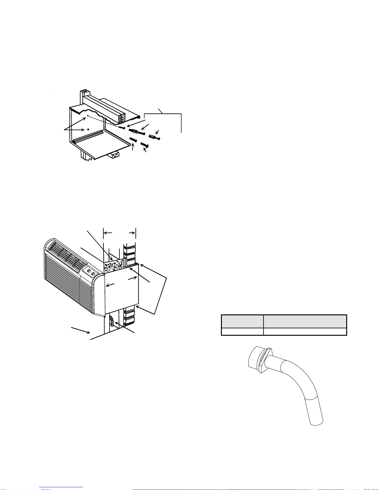
•Attach the sleeve using four #12x2” wood screws (for
wood constructed buildings) or four #12x2” masonry
screws (for cement or brick constructed buildings)
(Figure6). Makesurethewallconstructionisadequate
to support the unit.
Mounting
Holes
(Drilled by
Installer)
Plastic
Anchor Screws
Expansion
Anchor Bolt
Toggle Bolt
Wood Screw
Alternative
Fastening Method
(Field Supplied)
Figure 6
Attaching Wall Sleeve to Opening
•Provide adequate sealing and insulation around the
sleeveafteritisinstalled. SeeFigure7foroneexample
ofconstruction.
Steel
Lintel
Caulk Top,
Bottom, and
Both Sides
14 3/4"
375 mm
Maximum
(No Accessories)
Concrete
Lintel
Power Supply
Conduit
Finished
Floor
163/4"
426mm
Figure 7
Block and Brick Veneer Installation
•Do not use extension cords with the unit.
WallSleeveInstallation
Afterthewallopeningischeckedandapprovedforstrength,
location, size, and clearances, install the wall sleeve as
follows:
1. Remove the outside enclosure panel from the wall
sleeve.
2. Slide the wall sleeve into the wall opening. Do not
distortthecabinetshapetofitthewallopening;theunit
chassis must fit snugly and uniformly into the wall
sleeve.
3. Locatethe sleevewithintherangeofminimumprojec-
tions, as shown in Figure 2, so both sides are at least
the minimum projection from the wall.
4. Checkthelevelofthewallsleeve. Forproperdrainage,
the sleeve should be level from side to side and one-
quarter bubble front to back (outside).
5. Drill two holes in both sides of the wall sleeve so
mounting screws can be secured to wall supports.
See Figure 6 for location of screw holes. DO NOT
DRILL THROUGH BOTTOM OF SLEEVE.
6. Check the level of the wall sleeve and adjust if neces-
sary.
7. Caulk or seal around the outside of the entire sleeve.
8. If the unit chassis is not to be installed immediately,
replace the enclosure panel on the outside opening of
the sleeve to limit weather damage to the building
interior.
9. Recycleordisposeofpackagingmaterialsaccordingto
local codes.
CondensateDrainKit
Anoutdoorcondensatedrainkit (Figure8)isavailableonall
models. An accessory drain kit, DK900D, is available for
internal drain applications and must be purchased sepa-
rately. The drain kit must be installed before installing the
wallsleeveinthewall.Seethedrainkitforactualinstallation
instructions.
Kit Ordering
Number Description
DK9001 Internal Condensate Drain Kit
Figure 8
Condensate Drain Kit


 User manual")