5
1. Determine amount of air desired at main duct and at
extension duct. Using the table provided, select the
appropriate baffle.
MAIN DUCT EXT. DUCT
Small 3 11/16" x 31 3/4" 80% 20%
Large 4 5/16" x 31 3/4" 65% 35%
BAFFLE DIMENSIONS AIRFLOW
Table 1
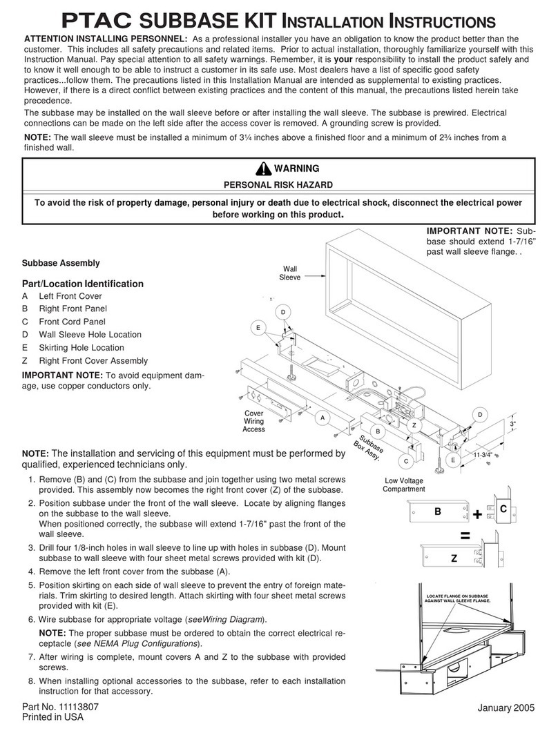
2. Place baffle on grille support brackets on main duct.
Ensure the two extruded holes of the baffle are on top
of the front bracket holes.
3. Install discharge air grille on top of the air baffle. Se-
cure the grille to the duct with pal nuts (provided) by
reaching through the opening in the bottom of the
duct.
Air Baffle Installation Instructions
SUPPORT
BRACKETS
DISCHARGE
AIR GRILLE
AIR BAFFLE
Air Grille Installation
MDKASSEMBLY
TRANSITION
MDK Installation Onto Transition Assembly
4. Place main duct assembly on the transition. Secure
the brackets to the wall sleeve with four #10 hex head
screws. Do not apply pressure on top of duct during
this installation!
5. Install two Phillips head screws into the top flange of
the main supply duct at extension duct connection.
Do not tighten screws. Leave space for one thickness
of the duct sheet metal between screw head and
main duct flange.
Main Supply Duct Top Flange
NOTE: Total length of duct extension assembly, including field
supplied duct between main and extension duct, should not exceed
15 effective feet (according to ASHRAE standards). For additional
dimensions, refer to Main Duct and Duct Extension Dimensions
illustration.
