4
WIRING INSTRUCTIONS
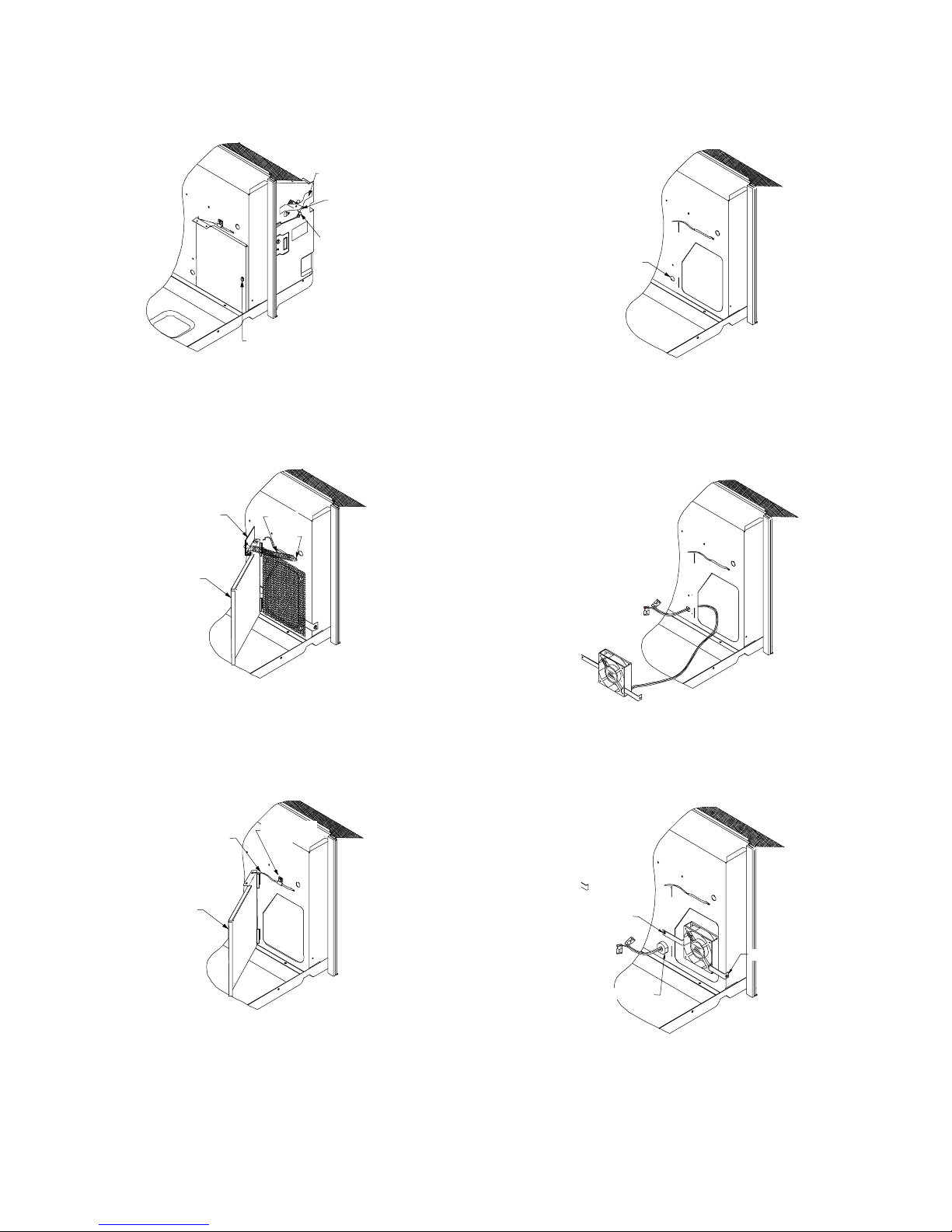
1. To gain access inside the control panel, remove the control
knobs and escutcheon, remove the three screws holding the
panel in position, and tilt control panel forward, being careful
not to pinch any wires (Figure 13).
123
ON
SCREW
SCREW
SCREW
Figure 13
2. Lift the control panel up so the control panel is free of its
hinges. Orient the control panel so there is easy access for
mounting components to the control panel (Figure 14).
Figure 14
3. Using the two #8 screws that are provided, screw the
transformer to the control panel in the transformer mounting
holes provided in the panel.
4. Mount the relay in one of the three relay mounting holes in
the control panel making sure that the threaded stud is in the
smaller hole and the metal tab is in the adjacent hole. Screw
the provided nut onto the threaded stud from the opposite
side of the control panel.
5. Remove the knockout for the vent switch (Figure 15) located
in the control panel and snap the vent switch in the knockout
hole with the terminals inside the control panel compartment.
The numbers on the switch should be facing toward the
control board. Place the supplied label just above the
switch.
Vent Switch
Knockout
Vent Switch
Figure 15
6. Using the two provided #8 screws, attach the terminal strip to
the partition panel inside the control panel compartment
(Figure 16).
Terminal
Strip
BK16
RD17
BK17
RD14
Figure 16
7. Once the wires are routed into the control panel compart-
ment, attach the door motor and vent fan (for PVK kits)
terminals to the 24 volt side of the transformer (see Wiring
diagrams).
8. Take BK 16 and RD17 fan motor wires from the control
board and place on the terminal strip (Figure 16).
9. Take BU10 wire from the #3 terminal of the relay and place
on the control board FAN LOW terminal. Take the BU15 wire
from the #8 terminal of the relay and place on the piggyback
terminal of BU10.
10. Take the BU4 wire from the #4 terminal of the relay and
place on the control board FAN HIGH terminal.
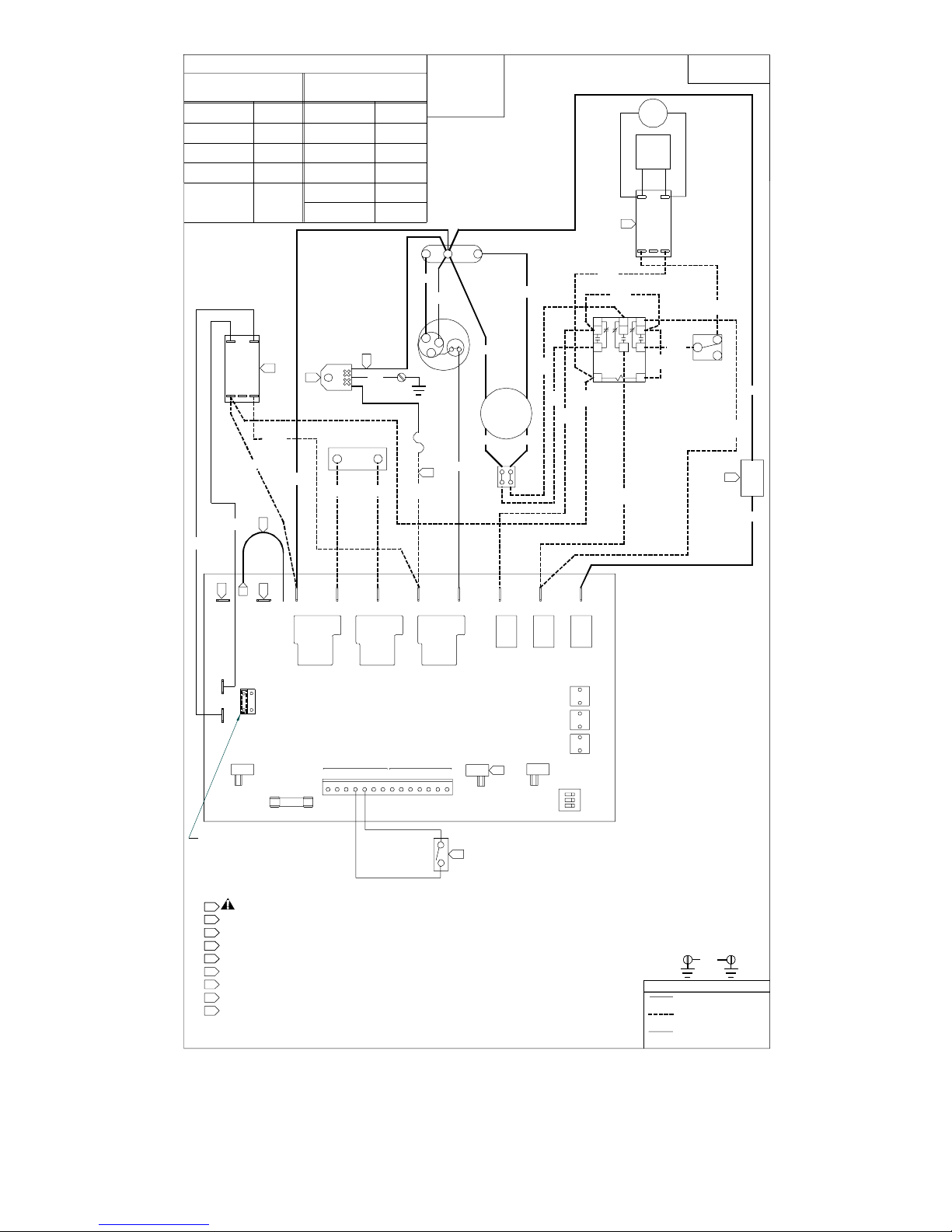
11. Please refer to the following schematics for proper electrical
wiring if the chassis has any of the following kits previously
installed:
Power Vent Kit
Power Door Kit
Hydronic Heat Kit
Hydronic Valves


 User manual")