AMCI SD7540A User manual

SD7540A
Stepper Drive
A
M
C
I
M
o
t
i
o
n
C
o
n
t
r
o
l
P
r
o
d
u
c
t
s
ADVANCED
MICRO CONTROLS INC.
U
s
e
r
M
a
n
u
a
l
Manual #: 940-0S040

Important User Information
The products and application data described in this manual are useful in a wide variety of different
applications. Therefore, the user and others responsible for applying these products described
herein are responsible for determining the acceptability for each application. While efforts have
been made to provide accurate information within this manual, AMCI assumes no responsibility for
the application or the completeness of the information contained herein. Throughout this manual the
following two notices are used to highlight important points.
WARNINGS tell you when people may be hurt or equipment may be damaged if the procedure is
not followed properly.
CAUTIONS tell you when equipment may be damaged if the procedure is not followed properly. No
patent liability is assumed by AMCI, with respect to use of information, circuits, equipment, or
software described in this manual. The information contained within this manual is subject to
change without notice. UNDER NO CIRCUMSTANCES WILL ADVANCED MICRO CONTROLS,
INC. BE RESPONSIBLE OR LIABLE FOR ANY DAMAGES OR LOSSES, INCLUDING INDIRECT
OR CONSEQUENTIAL DAMAGES OR LOSSES, ARISING FROM THE USE OF ANY
INFORMATION CONTAINED WITHIN THIS MANUAL, OR THE USE OF ANY PRODUCTS OR
SERVICES REFERENCED HEREIN.
Standard Warranty
ADVANCED MICRO CONTROLS, INC. warrants that all equipment manufactured by it will be free
from defects, under normal use, in materials and workmanship for a period of [18] months. Within
this warranty period, AMCI shall, at its option, repair or replace, free of charge, any equipment
covered by this warranty which is returned, shipping charges prepaid, within one year from date of
invoice, and which upon examination proves to be defective in material or workmanship and not
caused by accident, misuse, neglect, alteration, improper installation or improper testing. The
provisions of the “STANDARD WARRANTY” are the sole obligations of AMCI and excludes all
other warranties expressed or implied. In no event shall AMCI be liable for incidental or
consequential damages or for delay in performance of this warranty.
Returns Policy
All equipment being returned to AMCI for repair or replacement, regardless of warranty status, must
have a Return Merchandise Authorization number issued by AMCI. Call (860) 585-1254 with the
model and serial numbers along with a description of the problem. A “RMA” number will be issued.
Equipment must be shipped to AMCI with transportation charges prepaid. Title and risk of loss or
damage remains with the customer until shipment is received by AMCI.
24 Hour Technical Support Number
Technical Support, in the form of documents, FAQs, and sample programs, is available from our
website, www.amci.com. 24 Hour technical support is also available on this product. For technical
support, call (860) 585-1254. Your call will be answered at the factory during regular business
hours, Monday through Friday, 8AM - 5PM EST. During non-business hours, an automated system
will ask you to leave a detailed message and the telephone number that you can be reached at.
The system will page an engineer on call. Please have your product model number and a
description of the problem ready before you call.
Revision History
This manual, AMCI number 940-0S040, supercedes revision 1.1 of the SD7540A Stepper Driver
manual. First released, March 16, 2007 it updates several drawings and slightly modifies the
format. It applies to SD7540A stepper drives with a serial number D02070100 and above.
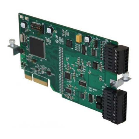
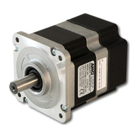
SD7540A Stepper Drive
20 Gear Drive, Plymouth Industrial Park, Terryville, CT 06786 page: 3
Tel: (860) 585-1254 Fax: (860) 584-1973 Web: www.amci.com
ADVANCED
MICRO CONTROLS INC.
The AMCI SD7540A Stepper Drive
The SD7540A is a powerful stepper motor
drive in a low cost, compact package.
Externally powered from a 24 – 75 VDC power
supply, this drive pack can operate up to
NEMA size 34 motors.
With up to 4 Amps rms(5.66 Amps peak) of
half step and microstepping capabilities, this
drive pack provides higher speed and torque
than any other drive in its class. Yet, it is easy
to connect to any differential or transistor
pulse and direction motion controller signal
.
Features
Compact Design – 2.2”X2.6” footprint
Optimized drive design
Industry standard Step/Direction control signals
More torque at higher speeds than competitive designs
Wide range of operating voltages, 24-75Vdc
Speeds to 2000 RPM
Anti-resonance circuitry
Motion controlled by Step & Direction input signals
Easy to use configuration software
Uses standard RS232 interface for programming
Programmable motor current
Programmable Idle Current Reduction
400, 1000, 2000, or 5000 selectable step resolution
AMCI quality and reliability
Single power supply
The SD7540A uses step and direction control signals generated from an external source such as
AMCI’s 3202 or 3601 stepper control modules. A logical diagram of the inputs is shown below.
CW Rotation CCW Rotation
STEP
DIR
The SD7540A is powered by an external DC supply with an operating range of 24 to 75Vdc. There
is an additional control input that can be used to disable the motor. This input can be left floating if
you are not using the disable motor feature.

SD7540A Stepper Drive
20 Gear Drive, Plymouth Industrial Park, Terryville, CT 06786 page: 4
Tel: (860) 585-1254 Fax: (860) 584-1973 Web: www.amci.com
ADVANCED
MICRO CONTROLS INC.
SD7540A Specifications
Environmental Specifications
Supply Voltage
24Vdc to 75Vdc max, 4 Arms maximum, user supplied.
The maximum supply input voltage includes power supply ripple
and motor back EMF.
Operating Temperature
32° to 122°F (0° to 50°C) Also, see Operating Notes on the following page.
Storage Temperature
–40° to 185°F (–40° to 85°C)
Relative Humidity
0 to 95%, non-condensing
Electrical Specifications
Motor Current
User Selectable – 4.0 Arms max 0.4 –4.0 Arms in 0.4 increments (10%-100%)
Default value – 3.20 Arms (80%)
Steps per Revolution
400, 1000, 2000, and 5000 – user selectable
Default value – 2000 steps/rev
Frequency on the Step input (max) - 100KHz
Idle current reduction time
1 sec
Idle current selection
0% to 70% of the maximum operating current
Default Value: 20%
Digital Inputs
Three opto-isolated differential inputs:
Step – Velocity/position command
Direction – Direction Control
Disable – Disables motion by reducing motor current to zero. The pins for this input can
be left open if the input is not used in your application.
Type of input
5V TTL logic
Input Current
15mA max
Input Connector
AMCI Part # MS-8P, provided (Phoenix part # MC 1.5/8-ST3.81)
8 screw terminal type – 16 AWG max.
Configuration Programming
Interface – RS232
Programming Software – AMCI SPI Interface software, Windows 2000/XP supported
Interface Cable – AMCI CSMD-5 5 ft serial cable (optional)

SD7540A Stepper Drive
20 Gear Drive, Plymouth Industrial Park, Terryville, CT 06786 page: 5
Tel: (860) 585-1254 Fax: (860) 584-1973 Web: www.amci.com
ADVANCED
MICRO CONTROLS INC.
Notes:
• Maximum temperature of the SD7540A drive mounting plate must not exceed 85
o
C (185
o
F). If these temperatures are exceeded the SD thermal protection circuit will shut down the
drive.
• Operating motor current - configure the minimum current needed to provide the torque for
your specific application. This will decrease the operating temperature of the SD7540 and
its attached motor
• Idle current: This is the amount of current that the drive provides to the motor when motion is
not occurring. To maximize drive efficiency and motor cooling, set the idle current to the
minimum value necessary to provide the required holding torque.
• Supply voltage: In general the higher supply voltage leads to higher switching losses and
higher heat generation in the motor-drive system.
• The SD7540A is designed to be mounted on a metal panel that will help dissipate heat. Any
metal surface larger than the SD7540A mounting plate, such as an enclosure wall, is
acceptable.

SD7540A Stepper Drive
20 Gear Drive, Plymouth Industrial Park, Terryville, CT 06786 page: 6
Tel: (860) 585-1254 Fax: (860) 584-1973 Web: www.amci.com
ADVANCED
MICRO CONTROLS INC.
• SD7540A Torque Curves with specified AMCI motor
Torque (oz-in)
SM23-130
(rev/sec)
0102030
0
25
50
75
100
125
72Vdc
0 600 1200 1800 (RPM)
0 2000 4000 6000
(Full Steps/sec)
48Vdc
24Vdc
POWER
SUPPLY
VOLTAGE
Torque (oz-in)
SM23-240
(rev/sec)
0102030
0
50
100
150
200
250
72Vdc
0 600 1200 1800 (RPM)
0 2000 4000 6000
(Full Steps/sec)
48Vdc
24Vdc
POWER
SUPPLY
VOLTAGE

SD7540A Stepper Drive
20 Gear Drive, Plymouth Industrial Park, Terryville, CT 06786 page: 7
Tel: (860) 585-1254 Fax: (860) 584-1973 Web: www.amci.com
ADVANCED
MICRO CONTROLS INC.
SD7540A Torque Curves
Torque (oz-in)
SM34-450
(rev/sec)
0102025
0
100
200
300
400
500
72Vdc
0 600 1200 1500 (RPM)
0 2000 4000 5000
(Full Steps/sec)
48Vdc
POWER
SUPPLY
VOLTAGE
515
300 900
1000 3000
72Vdc
48Vdc
24Vdc
Torque (oz-in)
SM34-850
(rev/sec)
0102025
0
200
400
600
800
1000
72Vdc
0 600 1200 1500 (RPM)
0 2000 4000 5000
(Full Steps/sec)
48Vdc
POWER
SUPPLY
VOLTAGE
515
300 900
1000 3000
Does not
operate at
24Vdc.

SD7540A Stepper Drive
20 Gear Drive, Plymouth Industrial Park, Terryville, CT 06786 page: 8
Tel: (860) 585-1254 Fax: (860) 584-1973 Web: www.amci.com
ADVANCED
MICRO CONTROLS INC.
Torque (oz-in)
SM34-1100
(rev/sec)
01020
0
240
480
720
960
1200
72Vdc
0 600 1200 (RPM)
02000
4000
(Full Steps/sec)
48Vdc
POWER
SUPPLY
VOLTAGE
515
300 900
1000 3000
Does not
operate at
24Vdc.
NOTE: Current setting for each torque curve was measured at 4.0 Arms.

SD7540A Stepper Drive
20 Gear Drive, Plymouth Industrial Park, Terryville, CT 06786 page: 9
Tel: (860) 585-1254 Fax: (860) 584-1973 Web: www.amci.com
ADVANCED
MICRO CONTROLS INC.
INSTALLATION
SD7540A Outline Drawing
The Indicator LED is on when power is applied to the drive and there is no motion. When the
SD7540A is accepting a pulse train input, the LED blinks at the same frequency as the
pulses being applied to the STEP input.
2.66"
(67.6)
2.96"
(75.2)
0.94"
(23.9)
2.20"
(55.9)
2.31"
(58.7)
1.84"
(46.7)
0.166"
(4.22)
dia.
Four places. Motor Input Connector (6 Pins)
Mates with AMCI #: MS-6P
Phoenix Contact #: MC1,5/6-ST-3,81
Indexer Input Connector (8 Pins)
Mates with AMCI #: MS-8P
Phoenix Contact #: MC1,5/8-ST-3,81
0.125"
(3.18)
1 2 3 4 5 6 7 8
Pin 1 +Vdc
Pin 2 Vdc Common
Pin 3 – Disable
Pin 4 + Disable
Pin 5 – Step
Pin 6 + Step
Pin 7 – Direction
Pin 8 + Direction
Pin 1 N.C.*
Pin 2 + A
Pin 3 – A
Pin 4 + B
Pin 5 – B
Pin 6 N.C.*
* No Connection (N.C.) Pins are
electrically isolated. These pins
can be used to land additional
wires of a six or eight lead motor.
( ) = Dimensions in millimeters
+
V
IN
–
V
IN
–
D
IS
+
D
IS
–
S
TP
+
S
TP
–
D
IR
+
D
IR
N
.
C
.
N
.
C
.
0.27"
(6.9)
1 2 3 4 5 6
0.27"
(6.9)
Indicator LED
+
–
+
AAB
–
B

SD7540A Stepper Drive
20 Gear Drive, Plymouth Industrial Park, Terryville, CT 06786 page: 10
Tel: (860) 585-1254 Fax: (860) 584-1973 Web: www.amci.com
ADVANCED
MICRO CONTROLS INC.
SD7540A Electrical Installation
Power supply inputs are NOT reverse connection protected. Applying
reverse voltage will damage unit.
Logic inputs are rated for 5Vdc max. Exceeding 5vdc will damage the
unit unless the recommended limiting resistors are used.
Control Signal Wiring
Motor Wiring
1 2 3 4 5 6 7 8
Pin 1 +Vdc
Pin 2 Vdc Common
Pin 3 – Disable
Pin 4 + Disable
Pin 5 – Step
Pin 6 + Step
Pin 7 – Direction
Pin 8 + Direction
+
VIN
–
VIN
–
DIS
+
DIS
–
STP
+
STP
–
DIR
+
DIR
0.27"
(6.9)
Pin 1 N.C.*
Pin 2 + A
Pin 3 – A
Pin 4 + B
Pin 5 – B
Pin 6 N.C.*
* No Connection (N.C.) Pins are
electrically isolated. These pins
can be used to land additional
wires of a six or eight lead motor.
N
.
C
.
N
.
C
.
0.27"
(6.9)
1 2 3 4 5 6
+
–
+
AAB
–
B
The motor pin out applies to units with a serial number
D02070100 and above. Prior to this serial number, the
motor connections were in a reversed order.

SD7540A Stepper Drive
20 Gear Drive, Plymouth Industrial Park, Terryville, CT 06786 page: 11
Tel: (860) 585-1254 Fax: (860) 584-1973 Web: www.amci.com
ADVANCED
MICRO CONTROLS INC.
Programmer Wiring – CSMD-5 cable
SD7540A Connector – AMCI part # MS-8P Serial Port Connector – DB-9
To SMD To PC Serial Port
1. DC Supply 24-75Vdc 1. N/C
2. DC Common Vdc com 2. RXD
3.DTR 3.TXD
4. RXD 4. DTR
5.RTS 5.GND
6. N/C 6. N/C
7.TXD 7.RTS
8. GND 8. N/C
9.N/C
Use a general purpose diode with a breakdown voltage greater than 30Vdc such as 1N4005
or 1N4148 to protect the SD RTS input.
The eight pin connector of the SD7540A is used for programming and control. The SD7540A drive
monitors the TXD signal coming from the computer’s serial port for a specific sequence of data.
When the SD7540A receives this data, it enters programming mode. To exit programming mode
you must cycle power on the SD7540A and reconnect the motion control signals. The SD7540A
automatically enters motion mode when power is re-applied.

SD7540A Stepper Drive
20 Gear Drive, Plymouth Industrial Park, Terryville, CT 06786 page: 12
Tel: (860) 585-1254 Fax: (860) 584-1973 Web: www.amci.com
ADVANCED
MICRO CONTROLS INC.
Wiring the SD7540A Control Signals to a Single-Ended Input
The SD7540A is built with differential inputs for optimal noise immunity. However many stepper
control circuits use single-ended (sinking or sourcing) control signals. The following schematics
show the correct wiring when using the SD7540A with single-ended control signals.
V
D C
R
L I M I T
5 V o l t s
1 2 V o l t s
1 5 V o l t s
2 4 V o l t s
N o n e
2 . 0 K
9
2 . 0 K
9
3 . 9 K
9
S D
Input
+ S T E P
O R
+ D I R E C T I O N
S T E P
O R
D I R E C T I O N
RL I M
Indexer
O u t p u t
V
D C
+ 5 t o + 2 4 V
S D
Input
+ S T E P
O R
+ D I R E C T I O N
S T E P
O R
D I R E C T I O N
RL I M
V
D C
+ 5 t o + 2 4 V
O p e n C o l l e c t o r S o u r c i n g O u t p u t
O p e n C o l l e c t o r S i n k i n g O u t p u t
Indexer
O u t p u t
S h i e l d e d T w i s t e d
P a i r C a b l e
S h i e l d e d T w i s t e d
P a i r C a b l e
Note: For the Disable input, the internal resistor is 1 kΩ. For the Step and Direction inputs,
the internal resistor is 316 Ω
Disable Input Wiring
The Disable Input on the SD7540A will shut off motor current when active. With the exception of
the internal resistor value, the circuitry of the Disable Input is identical to the Step and Direction
Inputs.
The SD7540A does not accept directional pulses while the Disable Input is active.
If not used, the Disable Input pins can be left open. The SD7540A will never disable the motor
current if these pins are left open.

SD7540A Stepper Drive
20 Gear Drive, Plymouth Industrial Park, Terryville, CT 06786 page: 13
Tel: (860) 585-1254 Fax: (860) 584-1973 Web: www.amci.com
ADVANCED
MICRO CONTROLS INC.
CHANGING THE SD7540A CONFIGURATION SETTINGS
Equipment required for changing the drive settings:
• Power supply – 24 to 75VDC, 4 Amps;
• Programming cable - AMCI CSMD-5, 5 ft serial cable(optional). It connects the drive to a
PC. The connections are described in the document. The drive circuit provides optical
isolation from the PC;
• PC running Windows 98/2000/XP;
• AMCI SPI Programming software, downloadable from the AMCI website (www.amci.com);
Procedure:
1. Install the AMCI SPI Programming software on the PC.
2. Connect the programming cable(AMCI part# CSMD-5, optional) to the SD7540A.
3. Connect the power supply to the same connector (follow the specified polarity).
4. Connect the D-Sub connector of the programming cable to the serial port of the PC.
5. Run the AMCI SPI programming software. The following window will appear on the screen:

SD7540A Stepper Drive
20 Gear Drive, Plymouth Industrial Park, Terryville, CT 06786 page: 14
Tel: (860) 585-1254 Fax: (860) 584-1973 Web: www.amci.com
ADVANCED
MICRO CONTROLS INC.
6. Select the Port menu and choose the COM port that the cable is connected to:
7. Turn on the power supply to the drive. The LED indicator should light.
8. Press the Connect button. For a few seconds the TX and the RX lights can change their
color to green to inform that the program is establishing the communication. Once they
settle to red, the communication is established. The current settings of the drive will be
displayed (RESOLUTION, IDLE and CURRENT), together with the identification string of the
drive. The motor will be disabled until the next power up.
For example:
The firmware
version
Status
display

SD7540A Stepper Drive
20 Gear Drive, Plymouth Industrial Park, Terryville, CT 06786 page: 15
Tel: (860) 585-1254 Fax: (860) 584-1973 Web: www.amci.com
ADVANCED
MICRO CONTROLS INC.
9. If a change to a setting is required, the new setting is selected from the appropriate field.
By pressing the Defaults button, the default settings will appear:
• RESOLUTION 2000 steps/revolution;
• IDLE 20 %;
• CURRENT 80 %;
10. By pressing the Apply button, the new settings will be saved in the drive’s nonvolatile
memory. The process of saving and verifying the new settings will take about 8 seconds.
During this time a warning to wait is displayed in the status display of the window. When the
process ends, a message that the command is accepted is displayed.
11. Pressing the Test On button starts the self test. The motor will move back and forth quarter
of a revolution with slow speed until the Test button is pressed again. The LED of the
SD7540A will blink indicating the application of drive steps.
Pressing the Recall button (in the menu above) will display the SD7540A’s current settings in the
data windows.
ERROR MESSAGES:
•Check if power is applied to the motor;
• Check the wire connection;
• Check if the correct COM port is
selected;

ADVANCED MICRO CONTROLS INC.
ADVANCED MICRO CONTROLS INC.ADVANCED MICRO CONTROLS INC.
ADVANCED MICRO CONTROLS INC.
20 GEARDRIVE, TERRYVILLE, CT 06786 T: (860) 585-1254 F: (860) 584-197
3
www.amci.com
Table of contents
Other AMCI Control Unit manuals

AMCI
AMCI SMD34E2 Instruction Manual

AMCI
AMCI SD17060E2 User manual

AMCI
AMCI SMD23 Series User manual

AMCI
AMCI SMD34K User manual

AMCI
AMCI 1141 User manual

AMCI
AMCI SMD17E2 User manual

AMCI
AMCI 2600-13 User manual

AMCI
AMCI 7551 Installation and operating instructions

AMCI
AMCI 3502 User manual

AMCI
AMCI PowerFlex 750 Series User manual
Popular Control Unit manuals by other brands

BENDIX
BENDIX ATR-2 ANTILOCK TRACTION VALVE Service data sheet

Bose
Bose Acoustimass 700 owner's guide

Whadda
Whadda WPI317 user manual

Texas Instruments
Texas Instruments TPA3255EVM user guide

Helios
Helios AIR1-SM DX Installation and operating instructions

Phoenix Contact
Phoenix Contact FL WLAN 1100 user manual