AMCI SMD34K User manual

M
ICRO CONTROLS INC.
ADVANCED
U
s
e
r
M
a
n
u
a
l
Manual #: 940-0S280

ADVANCED MICRO CONTROLS INC.
GENERAL INFORMATION
Important User Information
The products and application data described in this manual are useful in a wide variety of different applica-
tions. Therefore, the user and others responsible for applying these products described herein are responsible
for determining the acceptability for each application. While efforts have been made to provide accurate infor-
mation within this manual, AMCI assumes no responsibility for the application or the completeness of the
information contained herein.
UNDER NO CIRCUMSTANCES WILL ADVANCED MICRO CONTROLS, INC. BE RESPONSIBLE OR
LIABLE FOR ANY DAMAGES OR LOSSES, INCLUDING INDIRECT OR CONSEQUENTIAL DAM-
AGES OR LOSSES, ARISING FROM THE USE OF ANY INFORMATION CONTAINED WITHIN THIS
MANUAL, OR THE USE OF ANY PRODUCTS OR SERVICES REFERENCED HEREIN.
No patent liability is assumed by AMCI, with respect to use of information, circuits, equipment, or software
described in this manual.
The information contained within this manual is subject to change without notice.
This manual is copyright 2020 by Advanced Micro Controls Inc. You may reproduce this manual, in whole or
in part, for your personal use, provided that this copyright notice is included. You may distribute copies of this
complete manual in electronic format provided that they are unaltered from the version posted by Advanced
Micro Controls Inc. on our official website: www.amci.com. You may incorporate portions of this documents
in other literature for your own personal use provided that you include the notice “Portions of this document
copyright 2020 by Advanced Micro Controls Inc.” You may not alter the contents of this document or charge a
fee for reproducing or distributing it.
Standard Warranty
ADVANCED MICRO CONTROLS, INC. warrants that all equipment manufactured by it will be free from
defects, under normal use, in materials and workmanship for a period of [18] months. Within this warranty
period, AMCI shall, at its option, repair or replace, free of charge, any equipment covered by this warranty
which is returned, shipping charges prepaid, within eighteen months from date of invoice, and which upon
examination proves to be defective in material or workmanship and not caused by accident, misuse, neglect,
alteration, improper installation or improper testing.
The provisions of the "STANDARD WARRANTY" are the sole obligations of AMCI and excludes all other
warranties expressed or implied. In no event shall AMCI be liable for incidental or consequential damages or
for delay in performance of this warranty.
Returns Policy
All equipment being returned to AMCI for repair or replacement, regardless of warranty status, must have a
Return Merchandise Authorization number issued by AMCI. Call (860) 585-1254 with the model number and
serial number (if applicable) along with a description of the problem during regular business hours, Monday
through Friday, 8AM - 5PM Eastern. An "RMA" number will be issued. Equipment must be shipped to AMCI
with transportation charges prepaid. Title and risk of loss or damage remains with the customer until shipment
is received by AMCI.
24 Hour Technical Support Number
24 Hour technical support is available on this product. If you have internet access, start at www.amci.com.
Product documentation and FAQ’s are available on the site that answer most common questions.
If you require additional technical support, call (860) 583-1254. Your call will be answered by the factory dur-
ing regular business hours, Monday through Friday, 8AM - 5PM Eastern. During non-business hours an auto-
mated system will ask you to enter the telephone number you can be reached at. Please remember to include
your area code. The system will page an engineer on call. Please have your product model number and a
description of the problem ready before you call.
Waste Electrical and Electronic Equipment (WEEE)
At the end of life, this equipment should be collected separately from any unsorted municipal waste.

20 Gear Drive, Plymouth Ind. Park, Terryville, CT 06786
Tel: (860) 585-1254 Fax: (860) 584-1973 http://www.amci.com 3
TABLE OF CONTENTS
GENERAL INFORMATION
Important User Information ..................... 2
Standard Warranty ................................... 2
Returns Policy .......................................... 2
24 Hour Technical Support Number ........ 2
WEEE Statement ..................................... 2
About this Manual
Audience .................................................. 7
Applicable Units ...................................... 7
Navigating this Manual ............................ 7
Manual Conventions ................................ 7
Trademark Notices ................................... 7
Revision Record ....................................... 8
Revision History ............................ 8
Manual Layout ......................................... 8
Reference: SMD34K Specifications
The SMD34K Family .............................. 9
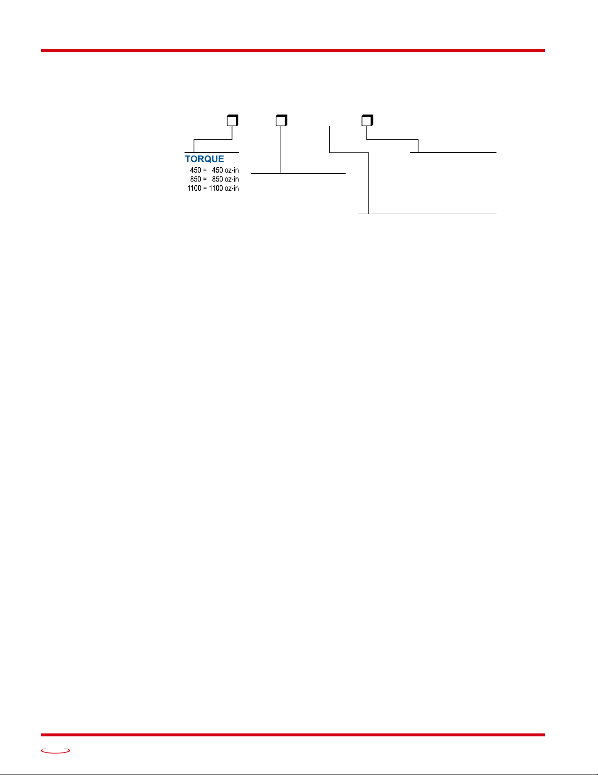
Part Numbering System ................. 10
General Functionality .................... 10
Input 3 and Distributed
Clock Functionality .......... 11
Encoder Functionality ................... 11
Specifications ........................................... 12
Conformance Markings ........................... 13
CE .................................................. 13
RoHS ............................................. 13
Indexer Functionality ............................... 13
Indexer Functionality (continued) ........... 14
Immediate Stops ............................ 14
Synchronizing Moves .................... 14
Additional Notes on
Stall Detection ............................. 14
Driver Functionality ................................. 15
Idle Current Reduction .................. 15
Available Discrete Inputs ......................... 16
Home Input .................................... 16
CW Limit Switch or
CCW Limit Switch ...................... 16
Start Indexer Move Input ............... 16
Emergency Stop Input ................... 16
Stop Jog or Registration
Move Input .................................. 17
Capture Encoder Position Input ..... 17
General Purpose Input ................... 17
Reference: SMD34K Specifications
(continued)
Optional Encoder ..................................... 17
Incremental Encoder ..................... 17
Absolute Multi-turn Encoder ........ 17
Status LED’s ............................................ 18
Run LED ....................................... 18
Error LED ..................................... 18
SMD34K Connectors ............................... 19
Ethernet Connectors ...................... 19
Digital Inputs Connector ............... 19
Power Connector ........................... 20
Torque and Power Curves ........................ 21
Power Supply Sizing ................................ 22
Regeneration Effects ..................... 23
Compatible Connectors and Cordsets ...... 24
Ethernet Connector ....................... 24
Digital Input Connector ................ 24
Power Connector ........................... 24
Ethernet Cordset ........................... 24
Digital Input Cordset .................... 24
Power Cordset ............................... 24
Reference: Motion Control
Definitions ................................................ 25
Units of Measure ........................... 25
Motor Position .............................. 25
Home Position ............................... 25
Count Direction ............................. 25
Starting Speed ............................... 25
Target Position .............................. 26
Relative Coordinates .......... 26
Absolute Coordinates ......... 26
Definition of Acceleration Types ............. 26
Linear Acceleration ....................... 26
Triangular S-Curve Accel. ............ 27
Trapezoidal S-Curve Accel. .......... 27
A Simple Move ........................................ 28
Controlled and Immediate Stops .............. 29
Host Control .................................. 29
Hardware Control ......................... 29
Basic Move Types .................................... 30
Relative Move ............................... 30
Controlled Stops ................. 30
Immediate Stops ................. 30
Absolute Move .............................. 31
Controlled Stops ................. 31
Immediate Stops ................. 31

TABLE OF CONTENTS
SMD34K User Manual
ADVANCED MICRO CONTROLS INC.
4
Reference: Motion Control
(continued)
CW/CCW Jog Move ..................... 32
Controlled Stops ................. 32
Immediate Stops ................. 32
CW/CCW Registration Move ....... 33
Controlled Stops ................. 34
Immediate Stops ................. 34
Assembled Moves .................................... 34
Blend Move ................................... 35
Controlled Stops ................. 36
Immediate Stops ................. 36
Dwell Move .................................. 36
Assembled Move Programming ............... 38
Control Bits – Output Data ........... 38
Control Bits – Input Data .............. 38
Programming Routine ................... 38
Saving an Assembled
Move in Flash ............................. 38
Indexed Moves ......................................... 39
Controlling Moves In Progress ................ 40
Jog Moves ..................................... 40
Registration Moves ....................... 40
Absolute and Relative Moves ....... 40
Assembled Moves ......................... 40
Reference: Calculating Move
Profiles
Constant Acceleration Equations ............. 41
Variable Definitions ...................... 41
Total Time Equations .................... 43
S-Curve Acceleration Equations .............. 44
Triangular S-Curve Accel. ............ 44
Trapezoidal S-Curve Accel. .......... 46
Determining Waveforms
by Values ................................... 48
Reference: Homing an SMD34K
Definition of Home Position .................... 51
Position Preset .......................................... 51
CW/CCW Find Home Commands ........... 51
Homing Inputs .......................................... 52
Physical Inputs .............................. 52
Network Data Input ...................... 52
Homing Configurations ............................ 52
Homing Profiles ....................................... 53
Home Input Only Profile .............. 53
Profile with
Backplane_Proximity_Bit ........... 54
Profile with Overtravel Limit ....... 55
Reference: Homing an SMD34K
(continued)
Controlling Find Home
Commands In Progress ........................... 56
Controlled Stops ............................ 56
Immediate Stops ............................ 56
Reference: Configuration
Data Format
CoE Registers ........................................... 57
Data Format .............................................. 57
CFG_Word_0 Format ................... 57
Configuration Word 1 Format ....... 60
Notes on Other
Configuration Words ................... 61
Invalid Configurations .............................. 61
Reference: Command Data Format
Command Bits Must Transition ............... 63
Output Data Format .................................. 63
Command Word 0 .................................... 64
Command Word 1 .................................... 66
Command Blocks ..................................... 67
Absolute Move .............................. 67
Relative Move ............................... 68
Hold Move .................................... 68
Resume Move ................................ 69
Immediate Stop ............................. 69
Find Home CW ............................. 70
Find Home CCW ........................... 70
Jog CW .......................................... 71
Registration Move CW ................. 71
Jog CCW ....................................... 72
Registration Move CCW ............... 72
Preset Position ............................... 73
Reset Errors ................................... 73
Run Assembled Move ................... 74
Preset Encoder Position ................. 74
Programming Blocks ................................ 75
First Block ..................................... 75
Segment Block .............................. 75
Input Data Format ..................................... 76
Status Word 0 Format ................... 76
Status Word 1 Format ................... 78
Notes on Clearing a Driver Fault .............. 79

20 Gear Drive, Plymouth Ind. Park, Terryville, CT 06786
Tel: (860) 585-1254 Fax: (860) 584-1973 http://www.amci.com
SMD34K User Manual
TABLE OF CONTENTS
5
Task 1: Installing the SMD34K
Location ................................................... 81
IP64 Rated Units ............................ 81
IP65/67 Rated Units ...................... 81
Safe Handling Guidelines ........................ 81
Prevent Electrostatic Damage ........ 81
Prevent Debris From
Entering the Unit ......................... 81
Remove Power Before
Servicing ...................................... 81
Operating Temperature Guidelines .......... 82
Mounting .................................................. 82
SMD34K-M12S Mounting ........... 82
SMD34K-M12P Mounting ........... 82
SMD34K Outline Drawing ............ 83
Connecting the Load ...................... 83
Power Connector ...................................... 84
Compatible Connectors
and Cordsets ................................ 84
Power Wiring ........................................... 85
Extending Power Leads ................. 85
Main Power Wiring Only .............. 85
Auxiliary Power, Single Supply .... 86
Auxiliary Power, Dual Supplies .... 86
Digital Input Connector ........................... 87
Compatible Connectors
and Cordsets ................................ 87
Digital Input Wiring ................................. 88
Cable Shields ................................. 88
Inputs 1 and 2 ................................ 88
Input 3 ............................................ 89
Network Connectors ................................ 89
Compatible Connectors
and Cordsets ................................ 90
TIA/EIA-568 Color Codes ............ 90
Task 2: EtherCAT System
Configuration
Install the ESI file ..................................... 91
Obtain the ESI file ........................ 91
Install the ESI file ......................... 91
Restart the Programming
System If Needed ........................ 91
Add the SMD34K to the Project .............. 91
Scan for the SMD34K Device ...... 91
Rename the Device ....................... 91
Configure the SMD34K ................ 92
Create a DUT ........................................... 93
Create Variables Based on the DUT ........ 93
Link Variable Names to I/O Words ......... 93
Task 3: Distributed Clock - SYNC0
Setup
Verify Main PLC Task Timing ................ 95
Create New PLC Task .............................. 96
Set Operational Mode .............................. 98
Set CFG_word1 Value to
Enable SYNC0 ....................................... 99

TABLE OF CONTENTS
SMD34K User Manual
ADVANCED MICRO CONTROLS INC.
6
Notes

20 Gear Drive, Plymouth Ind. Park, Terryville, CT 06786
Tel: (860) 585-1254 Fax: (860) 584-1973 http://www.amci.com 7
ABOUT THIS MANUAL
Audience
This manual explains the installation and operation of AMCI’s SMD34K Integrated Stepper Indexer/Driver/
Motors. It is written for the engineer responsible for incorporating these products into a design as well as the
engineer or technician responsible for their actual installation.
Applicable Units
This manual applies to all of the units in the SMD34K family.
Navigating this Manual
This manual is designed to be used in both printed and on-line forms. Its on-line form is a PDF document,
which requires Adobe Acrobat Reader version 7.0+ to open it. You are allowed to select and copy sections for
use in other documents and add notes and annotations. If you decide to print out this manual, all sections con-
tain an even number of pages which allows you to easily print out a single chapter on a duplex (two-sided)
printer.
Manual Conventions
Three icons are used to highlight important information in the manual:
NOTES highlight important concepts, decisions you must make, or the implications of those
decisions.
CAUTIONS tell you when equipment may be damaged if the procedure is not followed
properly.
WARNINGS tell you when people may be hurt or equipment may be damaged if the pro-
cedure is not followed properly.
The following table shows the text formatting conventions:
Manual Conventions
Trademark Notices
The AMCI logo is a trademark of Advanced Micro Controls Inc. EtherCAT® is a registered trademark and
patented technology, licensed by Beckhoff Automation GmbH, Germany. “Adobe” and “Acrobat” are regis-
tered trademarks of Adobe Systems Incorporated.
All other trademarks contained herein are the property of their respective holders.
Read this chapter to learn how to navigate through this manual and familiarize
yourself with the conventions used in it. The last section of this chapter highlights
the manual’s remaining chapters and their target audience.
Format Description
Normal Font Font used throughout this manual.
Emphasis Font Font used for parameter names and the first time a new term is introduced.
Cross Reference When viewing the PDF version of the manual, clicking on a blue cross refer-
ence jumps you to referenced section of the manual.
HTML Reference When viewing the PDF version of the manual, clicking on a red cross reference
opens your default web browser to the referenced section of the AMCI website
if you have Internet access.

ABOUT THIS MANUAL
SMD34K User Manual
ADVANCED MICRO CONTROLS INC.
8
Revision Record
This manual, 940-0S280 is the first release of this manual. It was released on October 19th, 2020.
Revision History
940-0S280: October 19th, 2020 - Initial Release
Manual Layout
You will most likely read this manual for one of two reasons:
If you are curious about the Integrated Stepper Indexer/Driver/Motor products from AMCI, this manual
contains the information you need to determine if these products are the right products for your applica-
tion. The first chapter, SMD34K Specifications contains all of the information you will need to fully
specify the right product for your application.
If you need to install and use an Integrated Stepper Indexer/Driver/Motor product from AMCI, then the
rest of the manual is written for you. To simplify installation and configuration, the rest of the manual is
broken down into references and tasks. Using an Integrated Stepper Indexer/Driver/Motor product
requires you to complete multiple tasks, and the manual is broken down into sections that explain how
to complete each one.
Manual Sections
Section Title Page Section Description
SMD34K Specifications 9Complete specifications for the SMD34K products.
Motion Control 25 Reference information on how the SMD34K can be used to con-
trol motion in your application.
Calculating Move Profiles 41 Reference information on calculating detailed move profiles.
Homing an SMD34K 51 Reference information on how to set the home position of the
SMD34K.
Configuration Data
Format 57 Reference information on the format of the CANopen over
EtherCAT (CoE) data that is used to configure the unit.
Command Data Format 63 Reference information on the format of the network data to and
from the SMD34K that is used to command it.
Installing the SMD34K 81 Task instructions covering how to install an SMD34K on a
machine. Includes information on mounting, grounding, and
wiring specific to the units.
EtherCAT System
Configuration 91 Task instructions that covers how to add an SMD34K to a
EtherCAT network.
Distributed Clock -
SYNC0 Setup 95 Optional Task instructions that covers how to configure an
SMD34K to use the Distributed Clock functionality of the
EtherCAT protocol.

20 Gear Drive, Plymouth Ind. Park, Terryville, CT 06786
Tel: (860) 585-1254 Fax: (860) 584-1973 http://www.amci.com 9
REFERENCE 1
SMD34K SPECIFICATIONS
The SMD34K Family
The SMD34K units are part of a growing product
line from AMCI with a simple concept: a stepper
indexer, driver, and motor that can be attached to
any popular industrial network. Each SMD34K
attaches to your Ethernet based network and com-
municates using the EtherCAT protocol.
EtherCAT uses standard Ethernet cabling, but
forgoes the full TCP/IP stack typically associated
with Ethernet communications. The EtherCAT
protocol transfers data to and from multiple
slaves with a single packet of information. Data
for each slave is located at a known position
within the packet. EtherCAT slave devices use a
hardware only solution to read and write data to
the packet before transmitting the packet to the
next slave. This results in a delay that is typically
4 microseconds or less. This results in a very fast
and deterministic network.
An EtherCAT Slave Information (ESI) file is
available for the SMD34K units. The ESI file is
required to add the device to the network. Con-
figuration of the SMD34K is accomplished using
the CANopen PDO and SDO objects. EtherCAT
supports CANopen through its CANopen over
Ethernet (CoE) interface. Motion commands and
status information is transmitted using the output
and input variables assigned to the SMD34K
when the EtherCAT system is configured.
Each unit also supports the Distributed Clock (DC) functionality of the EtherCAT system. This allows you to
synchronize the start of moves across devices using the SYNC0 signal instead of the SyncManager 2 event.
Each unit can be ordered with an optional incremental or absolute multi-turn encoder. This encoder gives you
the additional functionality of position verification and stall detection. The absolute multi-turn encoder allows
you to track machine position with power removed, eliminating the need to home the machine after cycling
power.
All units have a shaft seal and sealed connectors for their Ethernet, I/O, and power connections. These units
carry an IP64 environmental rating. Units can also be ordered sealed with an FDA approved epoxy. These units
carry an IP65/67 rating. These units are protected against low pressure washdown and can be submerged.
This manual is designed to get you up and running quickly with an SMD34K prod-
uct from AMCI. As such, it assumes you have some basic knowledge of stepper
systems, such as the resolution you want run your motor at, and the reasons why
you’d want to use Idle Current Reduction and the reasons why you wouldn’t. If
these terms or ideas are new to you, we’re here to help. AMCI has a great deal of
information on our website and we are adding more all the time. If you can’t find
what you’re looking for at http://www.amci.com, send us an e-mail or call us.
We’re here to support you with all of our knowledge and experience.
Figure R1.1 IP64 Rated SMD34K

SMD34K SPECIFICATIONS
SMD34K User Manual
ADVANCED MICRO CONTROLS INC.
10
The SMD34K Family (continued)
Part Numbering System
Figure R1.2 Part Numbering System
General Functionality
Each member of the SMD34K family has three integrated parts:
An indexer that accepts commands over an EtherCAT connection
A 5.4 Arms micro-stepping driver that accepts 24 to 80 Vdc as its input power source
A high torque size 34 stepper motor (450, 850, or 1,100 oz-in holding torque).
An incremental or absolute multi-turn encoder is also available for applications that require position feedback
or verification.
This combination of host and driver gives you several advantages:
Sophisticated I/O processing can be performed in the host (PLC or other controller) before sending
commands to the SMD34K unit
All motion logic is programmed in the host, eliminating the need to learn a separate motion control
language
The elimination of the separate indexer and driver lowers total system cost.
An SMD34K is powered by a nominal 24 to 80 Vdc power source, and can accept surge voltages of up to
88 Vdc without damage. The output motor current is fully programmable from 0.1 Arms to 5.4 Arms which
makes the SMD34K suitable to a wide range of applications. In addition to the Motor Current setting,
the Motor Steps per Turn, Idle Current Reduction, and Anti-Resonance Circuit features are also fully pro-
grammable. If you have used other stepper indexer products from AMCI, you will find programming an
SMD34K to be very similar to these products.
The SMD34K contains a true RMS motor current control driver. This means that you will always receive the
motor’s rated torque regardless of the Motor Steps/Turn setting. (Drivers that control the peak current to the
motor experience a 30% decrease in motor torque when microstepping a motor.) The combination of an
ultra-low inductance motor and a high-power, true RMS driver gives unprecedented torque vs. speed perfor-
mance for any DC application.
CONNECTOR TYPE
M12 =
Network: (2) 4 pin Female D-Coded
Digital Inputs: (1) 5 pin Male A-Coded
Power: (1) 4 pin Male S-Coded
Shaft Seal
IP64 Rating
M12 Connectors
SMD34K M12––
ENCODER
‘blank’= No encoder
A =Absolute Multi-turn Encoder
2,048 counts/turn.
E = Incremental Encoder
4,096 counts/turn max.
SEAL TYPE
S =
P = Conformal Coated,
IP65/67 Rating
Shaft Seal, IP64 Rating

20 Gear Drive, Plymouth Ind. Park, Terryville, CT 06786
Tel: (860) 585-1254 Fax: (860) 584-1973 http://www.amci.com
SMD34K User Manual
SMD34K SPECIFICATIONS
11
The SMD34K Family (continued)
General Functionality (continued)
The SMD34K units have three DC inputs that can used by the indexer. In some network configurations,
described below, only two inputs are available for use by the indexer. Configuration data from the host sets
how many inputs are available, and the function of these inputs.
Each input can be individually configured as a:
CW or CCW Limit Switch
Home Limit Switch
Capture Position Input (Will capture encoder position on units with the internal encoder.)
Stop Jog or Registration Move Input
Start Indexer Move
Emergency Stop Input
General Purpose Input
Input 3 and Distributed Clock Functionality
By default, the SMD34K is configured to use the
SyncManager 2 event of the EtherCAT network to control
the transfer of data from the EtherCAT Slave Controller (ECS) to the microprocessor that controls motion. This
allows the SMD34K to execute commands as soon as new data arrives. If two axes are to start simultaneously,
the actual delay between the two will be equal to the network delay between the two nodes. With a typical
delay of four microseconds plus the transit time between nodes, the delay between starts is inconsequential for
most machines.
On very fast machines, or large machines that require more than one transfer to update all axes, the EtherCAT
Distributed Clock (DC) functionality can be used to closely synchronize motion over multiple axes if using
the SyncMaster2 event proves to be ineffective. When using the DC functionality data transfer between the
ECS and the main processor is controlled with the SYNC0 signal.
In order to minimize delays in reacting to the SYNC0 signal, this signal is brought into the
main processor using the same processor pin used by DC Input 3. When the Distributed Clock
functionality is enabled on the SMD34K, Input 3 is unavailable as sensor input at the I/O
connector.The input must be left disconnected. If a cordset is used, wires for Input 3 must be
electrically isolated.
Encoder Functionality
All SMD34K units can be ordered with an internal incremental or absolute multi-turn encoder. Incremental
encoders can be programmed to 1,024, 2,048, or 4,069 counts per turn. Absolute encoders have a fixed reso-
lution of 2,048 counts per turn and encode a total of 221 turns. (32 bits total.) Using an encoder gives you the
ability to:
Verify position during or after a move
Detect motor stall conditions
Maintain machine position when power is removed if using an absolute encoder.
The motor position can be preset to the encoder position with a single command. SMD34K units with abso-
lute encoders allow you to preset the encoder position and save the resulting offset in Flash memory.

SMD34K SPECIFICATIONS
SMD34K User Manual
ADVANCED MICRO CONTROLS INC.
12
Specifications
Network Interface
100Base-TX. Two M12 4 pin D-coded connectors.
Supports all standard EtherCAT topologies.
Physical Dimensions
See page 83
Weight
SMD34K-450 (All versions) 4.50 lbs. (2.05 kg.)
SMD34K-850 (All versions) 7.10 lbs. (3.23 kg.)
SMD34K-1100 (All versions) 9.50 lbs. (4.32 kg.)
All weights are without mating connectors
Maximum Shaft Loads
Radial:45 lbs. (200N) at end of shaft
Axial:13.5 lbs. (60N)
Rotor Inertia
SMD34K-450: 1480 g·cm2
SMD34K-850: 3000 g·cm2
SMD34K-1100: 4500 g·cm2
Maximum Operating Temperature†
203°F /95°C. Note that this is the internal temperature
of the driver electronics, not maximum ambient tem-
perature. The temperature of the motor is not directly
measured.
Over Temperature Fault
Over temperature faults are reported in the
Network Input Data.
InputsElectrical Characteristics:
IN1 and IN2: Single ended sinking.
Accept 3.5 to 27 Vdc without the need for an
external current limiting resistor. Optoisolated,
1500 Vac/dc isolation.
IN3: Differential.
Accept 3.5 to 27 Vdc without the need for an
external current limiting resistor. Optoisolated,
1500 Vac/dc isolation.
Motor Current
Programmable from 0.1 to 5.4 Arms in 0.1 A steps.
DCPowerAUX Current
85 mA @ 24Vdc, 50 mA @48Vdc
Motor Counts per Turn
Programmable to any value from 200 to 32,767 steps
per revolution.
Internal Encoder (Optional)
Incremental encoder option supplies 1,024, 2,048, or
4,096 counts per turn.
Absolute encoder option supplies 2,048 counts per turn,
32 bit max. counts.
Idle Current Reduction
Programmable from 0% to 100% programmed motor
current in 1% increments. Motor current is reduced
to selected level if there is no motion for 1.5 seconds.
Current is restored to full value when motion is
started.
Environmental Specifications
Input Power ......... 24 to 80 Vdc, surge to 88 Vdc
without damage to unit.
Ambient Operating Temperature
............................. -40° to 122°F (-40° to 50°C)
Storage Temperature
............................. -40° to 185°F (-40° to 85°C)
Humidity ............. 0 to 95%, non-condensing
IP Rating ............. SMD34*2-*-M12S: IP64
........................ SMD34*2-*-M12P: IP65/67
Status LED’s
See Status LED’s section starting on page 18.
Connectors and Cables
All mating connectors are available separately under the
following AMCI part numbers.
Connector AMCI Part # Wire Strip Length Connection Type
Ethernet MS-28 18 AWG max. 0.197 inches Screw Terminals
I/O MS-31 18 AWG max. 0.197 inches Screw Terminals
Power MS-41 16 AWG max. 0.197 inches Screw Terminals
Cable AMCI Part # Length
Ethernet CNER-5M 5 meter
Digital I/O CNPL-2M 2 meter
Digital I/O CNPL-5M 5 meter
Power CNGL-5M 5 meter
† A properly designed system requires a heatsink sufficient to keep the operating temperature within
prescribed limits based on ambient conditions and required power levels.

20 Gear Drive, Plymouth Ind. Park, Terryville, CT 06786
Tel: (860) 585-1254 Fax: (860) 584-1973 http://www.amci.com
SMD34K User Manual
SMD34K SPECIFICATIONS
13
Conformance Markings
The SMD34K devices meet the requirements for the following conformance markings when installed and
operated in accordance with the instructions contained in their product documentation.
CE
Directive 2014/30/EU of the European Parliament and of the Council (EMC), of 26 February 2014 on
the harmonisation of the laws of the Member States relating to electromagnetic compatibility; per EN
61800-3:2004/A1:2012.
Directive 2014/35/EU of the European Parliament and of the Council (Low Voltage), of 26 February
2014 on the harmonisation of the laws of the Member States relating to the making available on the
market of electrical equipment designed for use within certain voltage limits; per EN 61010-1:2010.
RoHS
Directive (EU) 2015/863 (RoHS 3) and Directive 2011/65/EU (RoHS 2)
Indexer Functionality
The table below lists the functionality offered by the indexer built into the AMCI SMD34K units.
Table R1.1 Indexer Functionality
Feature Description
Synchronous
Moves
Using the Distributed Clock functionality of the EtherCAT system, multiple devices
can synchronize the start of their moves to the SYNC0 signal. Moves will begin
within ±25 microseconds of each other.
Programmable
Inputs
Each of the inputs can be programmed as a Home Limit, Over Travel Limit, Capture
Input, Manual Jog Stop, Start Indexer Move, E-Stop, or a General Purpose Input.
Programmable
Parameters
Starting Speed, Running Speed, Acceleration, Deceleration, and Accel/Decel Types
are fully programmable.
Homing
Allows you to set the machine to a known position. An SMD34K homes to a discrete
input and can use a bit in the Network Data as a home proximity input.
Jog Move
Allows you to drive the motor in either direction as long as the command is active.
Relative Move
Allows you to drive the motor a specific number of steps in either direction from the
current location.
Absolute Move
Allows you to drive the motor from one known location to another known
location.
Registration Move
Allows you to jog the motor in either direction based on a command from your host
controller. When a controlled stop is issued, the move will output a programmable
number of steps before coming to a stop.
Blend Move
Allows you to perform a sequence of relative moves without stopping between them.
Dwell Move
Allows you to perform a sequence of relative moves with a stop between each move
that has a programmable length of time. Used to create highly accurate move profiles
that avoid network latency issues.
Indexer Move
Allows you to program a move that is held in memory. The move is run when one of
the programmable inputs makes a transition.
Hold Move
Allows you to suspend a move, and optionally restart it, without losing your position
value.
Resume Move
Allows you to restart a previously held move operation.
Immediate Stop
Allows you to immediately stop all motion if an error condition is detected by your
host controller.
Stall Detection
When an SMD34K is purchased with an encoder option, the encoder can be used to
verify motion when a move command is issued.

SMD34K SPECIFICATIONS
SMD34K User Manual
ADVANCED MICRO CONTROLS INC.
14
Indexer Functionality (continued)
Immediate Stops
If a move is in progress when an Immediate Stop command is issued, the SMD34K responds
by shorting the motor’s windings together. This forces any regeneration energy to be dissi-
pated in the windings instead of being reflected back into the power supply. The windings can
be shorted for up to 300 milliseconds. Once the short is removed, the SMD34K will set a bit in
the network input data named Stopped, to show that motion is stopped and the unit is ready to
accept your next command.
Synchronizing Moves
By default, the SMD34K products use the SyncManager 2 event to control the transfer of data from the Ether-
CAT Slave Controller (ECS) to the microprocessor that controls motion. This allows the SMD34K to execute
commands as soon as new data arrives. When more than one axis is updated with a single EtherCAT packet,
the time difference between axis updates is very short. Updating multiple axes with a single packet allows the
EtherCAT network to out perform the update times of other industrial network protocols.
On very fast machines, or large machines that require more than one transfer to update all axes, the EtherCAT
Distributed Clock (DC) functionality can be used to closely synchronize motion over multiple axes if using
the SyncMaster2 event proves to be ineffective.
The EtherCAT Distributed Clock functionality is built into the ECS used by the SMD34K products. The
SMD34K can act as the reference clock for the system if it is the first device in the EtherCAT network. The
SYNC0 signal, which is based off of the Distributed Clock, can be use to synchronize the start of moves over
multiple devices. The time between when the SYNC0 signal is received by the main processor of the
SMD34K and when the driver begins to cause motion is 520 ± 25 microseconds. The 520 microseconds is
the time required to read the data from the ECS once the SYNC0 signal becomes active. The ±25 microsec-
onds is caused by the 20 kHz update frequency of the PWM drivers.
For the SMD34K, the minimum update time on the SYNC0 signal is two milliseconds. If the task time is less
than two milliseconds, the SYNC0 time must be a multiple of the task time.
In order to improve performance, the SYNC0 signal is brought into the main processor as
Input 3. When using the Distributed Clock (DC) functionality, Input 3 is unavailable for use
and an external connection to it must not be made.
Additional Notes on Stall Detection
When Stall Detection is enabled, the SMD34K monitors the encoder for position changes, regardless of
whether or not a move is in progress. If the error between the encoder position and the motor position exceeds
forty-five degrees, the SMD34K responds in the following manner:
The stall is reported in the network input data.
The motor position becomes invalid. (The machine must be homed or the motor position preset before
Absolute moves can be run again.
If a move was in progress, the move is stopped.
Note that a move does not have to be in progress for stall detection to be useful. As described later in this
chapter, there is an auxiliary power pin, DCPowerAUX, that powers the electronics of an SMD34K but does
not power the motor. The DCPowerMAIN pin powers both the electronics and the motor. The primary use of
the DCPowerAUX feature is to keep the unit on the network while power is removed from the motor. By
enabling stall detection, the SMD34K can notify the system if the motor shaft moves more than forty-five
degrees while main power is removed from the motor.

20 Gear Drive, Plymouth Ind. Park, Terryville, CT 06786
Tel: (860) 585-1254 Fax: (860) 584-1973 http://www.amci.com
SMD34K User Manual
SMD34K SPECIFICATIONS
15
Driver Functionality
This table summarizes the features of the stepper motor driver portion of the SMD34K units.
Table R1.2 Driver Functionality
Idle Current Reduction
Idle Current Reduction allows you to prolong the life of your motor by reducing its idling temperature. Val-
ues for this parameter range from 0% (no holding torque when idle) to 100%.
Idle current reduction should be used whenever possible. By reducing the current, you are reducing the I2R
losses in the motor. Therefore, the temperature drop in the motor is exponential, not linear. This means that
even a small reduction in the idle current can have a large effect on the temperature of the motor.
Note that the reduction values are “to” values, not “by” values. Setting a motor current to
4Arms and the current reduction to 25% will result in an idle current of 1Apk. (The SMD34K
always switches from RMS to peak current control when the motor is idle to prevent motor
damage due to excessive heating.)
Feature Benefits
RMS Current Control RMS current control give an SMD34K the ability to drive the motor at its
fully rated power regardless of the programmed steps per turn. There is no
reduction in power when microstepping that may occur with other drivers.
Programmable
Motor Current
RMS current supplied to the motor can be programmed from 0.1 to 5.4 amps
in 0.1 amp increments. Reducing the motor current to the minimum needed
for your application will significantly reduce the motor’s operating tempera-
ture
Programmable Idle
Current Reduction Extends motor life by reducing the motor current when motion is not occur-
ring. This extends the life of the motor by reducing its operating
temperature.
Programmable
Motor Steps/Turn Allows you to scale your motor count to a real world value. (counts per inch,
counts per degree, etc.)
Anti-Resonance Circuitry This feedback circuitry and algorithm gives the SMD34K the ability to mod-
ify motor current waveforms to compensate for mechanical resonance in
your system. This will give you smooth performance over the entire speed
range of the motor.
Over Temperature
Detection An SMD34K sets a warning bit in the network data when the internal tem-
perature of the unit approaches its safe operating threshold.
Over Temperature
Protection Protects your SMD34K from damage by removing power from the motor if
the internal temperature of the driver exceeds the safe operating threshold of
203°F/95°C.

SMD34K SPECIFICATIONS
SMD34K User Manual
ADVANCED MICRO CONTROLS INC.
16
Available Discrete Inputs
The SMD34K has a total of three discrete DC inputs that accept 3.5 to 27Vdc signals. (5 to 24Vdc nominal)
How your SMD34K uses these inputs is fully programmable. The active state of each input is also program-
mable. Programming their active states allow them to act as Normally Open (NO) or Normally Closed (NC)
contacts. Two of these inputs are open collector sinking and share their common connection. The third input
is fully differential and can be wired as a sinking or sourcing input.
When using the Distributed Clock (DC) functionality of the EtherCAT system, Input 3 is not
available for use. Internally, the Input 3 circuitry is used by the SYNC0 signal to trigger a syn-
chronous command update. Input 3 must not be attached to sensors when using the DC func-
tionality.
Home Input
Many applications require that the machine be brought to a known position before normal operations can
begin. This is commonly called “homing” the machine or bringing the machine to its “home” position. An
SMD34K allows you to define this starting position in two ways. The first is with a Position Preset command.
The second is with a sensor mounted on the machine. When you define one of the inputs as the Home Input,
you can issue commands to the SMD34K that will cause the unit to seek this sensor. How the SMD34K actu-
ally finds the home sensor is described in the reference chapter Homing an SMD34K starting on page 51.
CW Limit Switch or CCW Limit Switch
Each input can be defined as a CW or CCW Limit Switch. When used this way, the inputs are used to define
the limits of mechanical travel. For example, if you are moving in a clockwise direction and the CW Limit
Switch activates, all motion will immediately stop. At this point, you will only be able to jog in the counter-
clockwise direction.
Start Indexer Move Input
Indexer Moves are programmed through the Network Data like every other move. The only difference is that
Indexer Moves are not run until a Start Indexer Move Input makes a inactive-to-active state transition. This
allows an SMD34K to run critically timed moves that cannot be reliably started from the network due to data
transfer lags.
If the unit was ordered with the encoder option, and one of the discrete DC inputs is programmed as a Start
Indexer Move Input, then the encoder position data will be captured whenever the DC input makes a transi-
tion. An inactive-to-active state transition on the DC input will also trigger an Indexer Move if one is pending.
Emergency Stop Input
When an input is defined as an Emergency Stop, or E-Stop Input, motion will immediately stop when this
input becomes active. The driver remains enabled and power is supplied to the motor. Any type of move,
including a Jog or Registration Move, cannot begin while this input is active.
If a move is in progress when this input becomes active, the SMD34K responds by shorting the
motor’s windings together. This forces any regeneration energy to be dissipated in the windings
instead of being reflected back into the power supply. The windings will be shorted for up to
300 milliseconds. Once the short is removed, the SMD34K will set a bit in the network input
data to show that motion is stopped and the unit is ready to accept your next command.

20 Gear Drive, Plymouth Ind. Park, Terryville, CT 06786
Tel: (860) 585-1254 Fax: (860) 584-1973 http://www.amci.com
SMD34K User Manual
SMD34K SPECIFICATIONS
17
Available Discrete Inputs (continued)
Stop Jog or Registration Move Input
When an input is configured as a Stop Jog or Registration Move Input, triggering this input during a Jog
Move or Registration Move will bring the move to a controlled stop. The controlled stop is triggered on an
inactive-to-active state change on the input. Only Jog Moves and Registration Moves can be stopped this
way, all other moves ignore this input.
If the unit was order with an integral encoder, the encoder position data will be captured when the DC input
makes an inactive-to-active transition if it is configured as a Stop Jog or Registration Move Input. The
encoder position data is not captured if a Jog or Registration Move is not in progress. If you want to capture
encoder position data on every transition of a DC input, configure it as a Start Indexer Move Input.
Capture Encoder Position Input
As described in the Start Indexer Move Input and Stop Jog or Registration Move Input sections above, an
SMD34K can be configured to capture the encoder position value on a transition of a discrete DC input.
General Purpose Input
If your application does not require one or more of the inputs, you can configure the unused inputs as General
Purpose Inputs. The inputs are not used by the SMD34K, but their on/off state is reported in the network data
and is available to your host controller.
Optional Encoder
The SMD34K can be ordered with an integral encoder. The encoder is typically used for position verification
and stall detection. Additionally, an input can be configured to capture the encoder value when the input
makes an inactive to active transition. This captured value is written to the host controller. Two encoder
options are available:
Incremental Encoder
The incremental encoder can be programmed to 1,024, 2,048, or 4,096 counts per turn. The SMD34K has an
internal thirty-two bit counter associated with the encoder.
Absolute Multi-turn Encoder
The absolute encoder has a fixed resolution of 2,048 counts per turn. The absolute encoder is a multi-turn
device that encodes a total of 221 turns, yielding a full thirty-two bits of position resolution. The absolute
encoder can be used for position verification and stall detection, but its primary advantage is that it eliminates
the need to home the axis after cycling power to the drive.
Like many intelligent absolute encoders on the market today, the absolute encoder in the SMD34K uses a bat-
tery backed circuit to count zero crossings while power is removed from the rest of the device. The battery
life is 10 years in the absence of power. The circuit will accurately track position as long as the shaft acceler-
ation is limited to 160,000 degrees/sec2, (444.4 rev/sec2), or less.

SMD34K SPECIFICATIONS
SMD34K User Manual
ADVANCED MICRO CONTROLS INC.
18
Status LED’s
Each SMD34K has two status LED’s that shows the status of the
functional status of the device. As shown in figure R1.3, these
LEDs are located on the rear cover. They are named “RUN” and
“ERR”. Two additional LEDs are located on the near cover
between the two network connectors. These two LEDs are the
LINK/ACT LEDs for the Ethernet ports. They are on when there is
a physical connection between the device and the previous or next
device in the network. They blink when data is being transmitted
over the network.
Run LED
The green RUN LED indicates the logical state of the device.
Table R1.3 Module RUN LED States
Error LED
The ERR LED location houses a red/green LED. The red LED indicates an error state in the EtherCAT
protocol. The green LED indicates the operational state of the SMD34K itself. Both LEDs can be on
simultaneously.
Table R1.4 Red ERR LED States
Table R1.5 Green ERR LED States
LED State Description
Off Device in the EtherCAT Init state
Fast Blink
(4 Hz) Device in the EtherCAT Pre-Operational
(Pre-Op) state
Slow Blink
(1 Hz) Device in the EtherCAT Safe-Operational
(Safe-Op) state
Steady Green Device in the EtherCAT Operational (Op)
state.
Red LED State Description
Off No errors in device operation
Single blink
200 ms ON / 1 s OFF Problems with synchronization such as with the Distrib-
uted Clock (DC) PLL.
Double Blink
200 ms Pulses / 1 s between SYNC manager watchdog timeout. The master has not
updated the output data in the configured time interval. The
SMD34K has switched to the Safe-OP state.
Slow Blink
(1 Hz) All other issues, such as cable disconnect. The SMD34K
has switched to the Safe-OP state.
Green LED State Description
Solid Green Device in the EtherCAT Init state
Very Slow Blink Green‡
(0.5 Hz) Driver Fault (Overtemperature fault, etc.)
Slow Blink Green‡
(1 Hz) Unsuccessful write to flash memory
Fast Blink Green‡
(4 Hz) Successful write to flash memory
Figure R1.3 Rear Cover Status LED’s
POWER
24 to 80 Vdc
DIGITAL INPUTS
5 to 24 Vdc
ERR
RUN
OUT
IN

20 Gear Drive, Plymouth Ind. Park, Terryville, CT 06786
Tel: (860) 585-1254 Fax: (860) 584-1973 http://www.amci.com
SMD34K User Manual
SMD34K SPECIFICATIONS
19
SMD34K Connectors
Ethernet Connectors
Figure R1.4 shows the placement of the connectors on an SMD34K
unit. Figure R1.5 shows the pinout of the Ethernet connectors when
viewed from the back of the SMD34K. Each Ethernet port on the
SMD34K is an “auto-sense” port that will automatically switch
between 10baseT and 100baseT depending on the network equip-
ment it is attached to. Each port also has “auto switch” capability.
This means that a standard cable can be used when connecting the
SMD34K to any device, including a personal computer.
Figure R1.5 Ethernet Connector Pinout
The connector is a standard four pin D-coded female M12 connector that is rated to IP67 when the mate is
properly installed.
Digital Inputs Connector
All digital inputs are made at the Digital Inputs Connector. This connector is a standard five pin A-coded M12
connector that is rated to IP67 when the mate is properly installed. Figure R1.6 shows the pinout of the con-
nector when viewed from the back of the SMD34K.
Figure R1.6 M12 Input Connector
Digital Inputs 1 and 2 are single ended, sinking inputs that share a common DC reference. (Pin 3, IN1/2Com)
Input 3 is a differential input, and can be wired as a sinking or sourcing input.
All of the inputs accept a nominal 5 Vdc to 24 Vdc signal without the need of a current limiting resistor.
Additional information on how the digital inputs can be used can be found in the Available Discrete Inputs
section of the chapter, starting on page 16.
Figure R1.4 SMD34K Connector Locations
POWER
24 to 80 Vdc
DIGITAL INPUTS
5 to 24 Vdc
ERR
RUN
OUT
IN
Pin 1: +Tx
Pin 2: +Rx
Pin 4: –Rx
Pin 3: –Tx
ETHERNET
Ports 1 & 2

SMD34K SPECIFICATIONS
SMD34K User Manual
ADVANCED MICRO CONTROLS INC.
20
SMD34K Connectors (continued)
Power Connector
Figure R1.7 shows the pinout of the power connector when viewed from the back of the SMD34K. This con-
nector is a standard four pin S-coded M12 connector.
Figure R1.7 M12 Power Connector
There are two power pins and two DC common pins. DCPowerMAIN powers both the control electronics and
the motor. DCPowerAUX powers only the control electronics. Using the DCPowerAUX pin is optional. If your
application requires you to cut power to your motor under some conditions, using the DCPowerAUX pin allows
you to cut power to your motor without losing your network connection.
If the unit was ordered with an encoder, the DCPowerAUX pin will also maintain power to the
encoder. If the motor shaft is rotated while motor power is removed, the encoder position will
update. (The motor position will not update.) Once power is restored to the motor, a Preset
Position command can be issued to restore the correct motor position without having to go
through a homing sequence. If Stall Detection is enabled on the SMD34K, it will also be able
to tell the system if the motor shaft rotated more than forty-five degrees with power removed.
S-coded connectors are typically used in AC applications, while T-coded connectors are typi-
cally used in DC applications. However, T-coded connectors and cordsets are typically limited
to a maximum voltage of 60 Vdc. The SMD34K can be run at voltages as high as 80 Vdc, so
the decision was made to use the S-coded connectors. Most S-coded cordsets, including the
CNGL-5M cable from AMCI, have three black wires and a single green/yellow wire. When
using such a cable with an SMD34K, it is strongly recommended to label the wires by pin
number before installing the cordset.
Table of contents
Other AMCI Control Unit manuals

AMCI
AMCI 7500 Series User manual

AMCI
AMCI 2600-13 User manual

AMCI
AMCI 3502 User manual

AMCI
AMCI 7551 Installation and operating instructions

AMCI
AMCI SMD23 Series User manual

AMCI
AMCI SMD34E2 Instruction Manual

AMCI
AMCI SMD17E2 User manual

AMCI
AMCI 1141 User manual

AMCI
AMCI SD17060E2 User manual

AMCI
AMCI PowerFlex 750 Series User manual