AMCI 3502 User manual

20 Gear Drive, Plymouth Industrial Park, Terryville, CT 06786 page: 1
Tel: (860) 585-1254 Fax: (860) 584-1973 Web: www.amci.com Manual Revision 1.0
3502 Module
SLC 500 Motion Controller
Module Overview
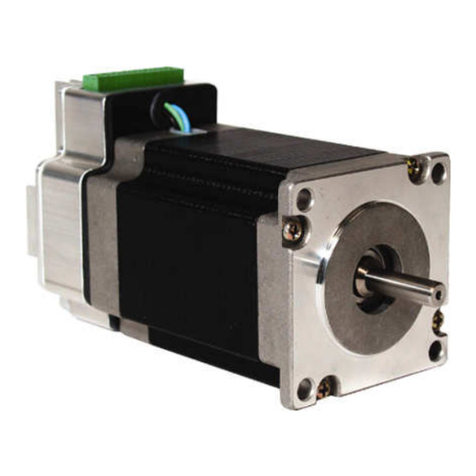
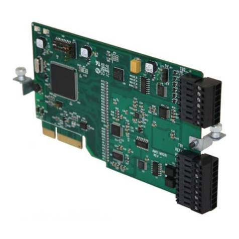
The 3502 module is a one-axis stepper controller that occupies one slot in a SLC 500 rack.
This unit receives profile data from the PLC and outputs Step and Direction signals or
Clockwise/Counter Clockwise pulses to a stepper driver. Inputs on the module allow for homing,
over travel, and emergency stop. A 5V differential incremental encoder can be attached to the
unit to provide feedback information.
The 3502 module uses 8 input and 8 output registers to communicate with the PLC. Status
bits, the Current Position, and Encoder Count Value, are reported to the Input Registers. The 8
output registers have two purposes. First, they are used to configure the module with
parameters such as Output Type, Homing Type, Inputs Used, Input Active Level, and Starting
Speed. Second, they are used to send the move commands, along with the distance, speed,
and acceleration and deceleration rates used to define the move profile.
Some of the data used by the 3502 can exceed 32767, the value that can be contained in one
16 bit register. Because of this, these parameters are divided into two words, the Most
Significant Word (MSW) and the Least Significant Word (LSW). The MSW has the 1000s places
and the LSW has the 1s, 10s and 100s places. Negative values are handled using a sign
magnitude format where the Most Significant Bit in the MSW is set to indicate a negative value.
For example:
Value MSW
(decimal)
MSW
(hex)
LSW
(decimal)
LSW
(hex)
-12,345 -32,756 16#800C 345 16#0159
12,000 12 16#000C 0 16#0000
-12,000 -32,756 16#800C 0 16#0000
345 0 16#0000 345 16#0159
-345 -32768 16#8000 345 16#0159
Because the 3502 module does not use a non-volatile memory, it must be configured at every
power up.
Sample programs for the 3502 are available from the following page of our website.
https://www.amci.com/industrial-automation-support/sample-progams/
Waste Electrical and Electronic Equipment (WEEE)
At the end of life, this equipment should be collected separately from
any unsorted municipal waste.

20 Gear Drive, Plymouth Industrial Park, Terryville, CT 06786 page: 2
Tel: (860) 585-1254 Fax: (860) 584-1973 Web: www.amci.com Manual Revision 1.0
3502 Module
SLC 500 Motion Controller
General Information
Important User Information
The products and application data described in this manual are useful in a wide variety of
different applications. Therefore, the user and others responsible for applying these products
described herein are responsible for determining the acceptability for each application. While
efforts have been made to provide accurate information within this manual, AMCI assumes no
responsibility for the application or the completeness of the information contained herein.
Throughout this manual the following two notices are used to highlight important points.
WARNINGS tell you when people may be hurt or equipment may be damaged if the procedure
is not followed properly.
CAUTIONS tell you when equipment may be damaged if the procedure is not followed
properly. No patent liability is assumed by AMCI, with respect to use of information, circuits,
equipment, or software described in this manual. The information contained within this manual
is subject to change without notice. UNDER NO CIRCUMSTANCES WILL ADVANCED MICRO
CONTROLS, INC. BE RESPONSIBLE OR LIABLE FOR ANY DAMAGES OR LOSSES, INCLUDING
INDIRECT OR CONSEQUENTIAL DAMAGES OR LOSSES, ARISING FROM THE USE OF ANY
INFORMATION CONTAINED WITHIN THIS MANUAL, OR THE USE OF ANY PRODUCTS OR
SERVICES REFERENCED HEREIN.
Standard Warranty
ADVANCED MICRO CONTROLS, INC. warrants that all equipment manufactured by it will be free
from defects, under normal use, in materials and workmanship for a period of [18] months.
Within this warranty period, AMCI shall, at its option, repair or replace, free of charge, any
equipment covered by this warranty which is returned, shipping charges prepaid, within one
year from date of invoice, and which upon examination proves to be defective in material or
workmanship and not caused by accident, misuse, neglect, alteration, improper installation or
improper testing. The provisions of the “STANDARD WARRANTY” are the sole obligations of
AMCI and excludes all other warranties expressed or implied. In no event shall AMCI be liable
for incidental or consequential damages or for delay in performance of this warranty.
Returns Policy
All equipment being returned to AMCI for repair or replacement, regardless of warranty status,
must have a Return Merchandise Authorization number issued by AMCI. Call (860) 585-1254
with the model and serial numbers along with a description of the problem. A “RMA” number
will be issued. Equipment must be shipped to AMCI with transportation charges prepaid. Title
and risk of loss or damage remains with the customer until shipment is received by AMCI.
24 Hour Technical Support Number
Technical Support, in the form of documents, FAQs, and sample programs, is available from our
website, www.amci.com. 24 Hour technical support is also available on this product. For
technical support, call (860) 583-7271. Your call will be answered by the factory during regular
business hours, Monday through Friday, 8AM - 5PM EST. During non-business hours, an
automated system will ask you to leave a detailed message and the telephone number where
you can be reached. The system will page an engineer on call. Please have your product model
number and a description of the problem ready before you call.
20 Gear Drive, Plymouth Industrial Park, Terryville, CT 06786 page: 3
Tel: (860) 585-1254 Fax: (860) 584-1973 Web: www.amci.com Manual Revision 1.0
3502 Module
SLC 500 Motion Controller
Table of Contents
Installing the 3502 Module Chapter 1 4
I/OConfiguration 4
Module Specifications 5
FrontPanel&LEDFunctions 6
OutputSignals 6
Connector Pinout and Wiring 7
DiscreteInputWiring 7
Single Ended Encoder Wiring 8
DiagnosticFeedbackWiring 8
Calculating Move Profiles Chapter 2 9
Configuration Programming Chapter 3 11
ConfigurationBits 13
InputActiveLevel 13
StartingSpeed 13
Invalid Configurations 14
Configuration Mode Input Data 14
Command Mode Operations Chapter 4 15
Absolute&RelativeMoves 15
HoldMove 16
ResumeMove 16
ImmediateStop 16
FindHome+/(CW),FindHome-/(CCW)17
Jog Move +/(CW), Jog Move -/(CCW) 19
OneShotJog 20
PresetCurrentPosition 20
PresetEncoderPosition 20
ResetErrors 20
BlendMove 21
DiagnosticFeedback 22
Command Mode Output Data Chapter 5 23
CommandWords 23
CommandBits 23
BlendMoveProgramming 25
Command Mode Input Data Chapter 6 27
StatusBits 27
InputWordFunctions 28
Status&ErrorBitFunctions 29
Manual Revision History 31

20 Gear Drive, Plymouth Industrial Park, Terryville, CT 06786 page: 4
Tel: (860) 585-1254 Fax: (860) 584-1973 Web: www.amci.com Manual Revision 1.0
3502 Module
SLC 500 Motion Controller
Chapter 1: Installing the 3502 module
WARNING Disconnect power before installing or remove the 3502 module.
1. Verify that your system’s power supply has adequate reserve current capacity. The
3502 module requires 200mA at +5Vdc.
2. Align the module with the grooves in the top and bottom of the SLC rack system and
slide the module backwards until the tabs on the plastic housing lock the module in
place.
SLC 500 Rack Configuration
1. Double Click on I/O Configuration in the Project Tree.
2. Select the desired unused slot, scroll to the bottom of the list of available modules and
double click on Other – Requires I/O Card Type ID.

20 Gear Drive, Plymouth Industrial Park, Terryville, CT 06786 page: 5
Tel: (860) 585-1254 Fax: (860) 584-1973 Web: www.amci.com Manual Revision 1.0
3502 Module
SLC 500 Motion Controller
3. Type a value of 3535 in the “Other” type IO card window that opens.
4. Input Data (data from the 3502 module to the PLC) will appear in Input Image Table
registers I:X.0 to I:X.7, where X is the slot number. Output Data (data from the PLC to
the 3502 module) will be written to registers O:X.0 to O:X.7, where X is the slot
number.

20 Gear Drive, Plymouth Industrial Park, Terryville, CT 06786 page: 6
Tel: (860) 585-1254 Fax: (860) 584-1973 Web: www.amci.com Manual Revision 1.0
3502 Module
SLC 500 Motion Controller
Module Specifications
Backplane Current Draw: 200mA @5Vdc
External User Power: 90mA @ 24Vdc
Stepper Outputs
Output Voltage: +5Vdc differential (3.5Vdc to 4Vdc peak typical)
Maximum Output Current: 20mA
Maximum Output Frequency: 250kHz
Encoder Inputs
5V differential encoder only
A, B, and Z Maximum Input Current: 10mA per channel @5Vdc
The A and B signals must both be connected to the 3502 module to have the encoder data
increment or decrement.
Discrete Inputs
Input Type: Sinking
Input Voltage Range: On = 8 to 24Vdc
Off = 0 to 2Vdc
Input Current: 15mA @ 24Vdc
Response Time (On and Off): 5s
Scanning Time: The input must be on for 250ms to be detected by the module.
Active State: The discrete inputs can be configured to be Active High (for use with a
normally open contact) or Active Low (for use with a normally closed
contact).
Input Functions: External Input, Home Input, Home Proximity Input, Emergency Stop, CW
Limit Switch, and CCW Limit Switch. (The External Input only affects Jog
Moves. The Home and Home Proximity Inputs only affects Homing
operations.)
Environmental Conditions
Operating Temperature: 0 to 60° C
Relative Humidity: 5 to 95% (non-condensing)
Storage Temperature: -40 to 85° C

20 Gear Drive, Plymouth Industrial Park, Terryville, CT 06786 page: 7
Tel: (860) 585-1254 Fax: (860) 584-1973 Web: www.amci.com Manual Revision 1.0
3502 Module
SLC 500 Motion Controller
Front Panel
Output Signals
The 3502 module can be programmed to output either Step and Direction signals or CW / CCW
steps. There is no advantage to either type; you must simply configure the 3502 module to
match the input type of your driver. The two types of signals are illustrated below.
Step and Direction Output
CW and CCW Step Outputs
Ste
p
Out
p
ut
CW Motion or Increasin
g
Counts
CCW Motion or Decreasin
g
Counts
CW Output Increasin
g
Counts
Decreasin
g
Counts
Direction Out
p
ut
CCW Output
RUN
Off: Module not powered or not operating correctly
Solid Green: Module Operating Correctly
CW
Off: Motion not occurring in the CW direction
Solid Green: Motion occurring in the CW direction
CCW
Off: Motion not occurring in the CCW direction
Solid Green: Motion occurring in the CCW direction
ERR
OFF: No Command Errors exist
Solid Red: An Error occurred during Command operations
FLT
OFF: No Configuration Error exists
Solid Red: The 3502 is either not configured or has been sent invalid Configuration
Data.
STEPPER

20 Gear Drive, Plymouth Industrial Park, Terryville, CT 06786 page: 8
Tel: (860) 585-1254 Fax: (860) 584-1973 Web: www.amci.com Manual Revision 1.0
3502 Module
SLC 500 Motion Controller
Connector Pin Out
The input connector is included with the 3502 module and consists of an eighteen position
Removable Terminal Block. The following diagram shows the wiring of this Terminal Block.
Note: Pin 1 is located on the upper left when the Terminal Block is plugged into the unit.
Wiring Notes:
The 3502 module uses a 9638 differential line driver in series with a 10resistor for the
stepper (+/- step and +/- direction) outputs.
Stepper signals are generally low voltage, low power signals. If you are using A-B
guidelines for cabling installation, treat the cable as a Category 2 cable. It can be
installed in conduit along with other low power cabling such as communication cables and
low power ac/dc I/O lines. It cannot be installed in conduit with ac power lines or high
power ac/dc I/O lines.
If the signal cable must cross power feed lines, it should do so at right angles.
Route the cable at least five feet from high voltage enclosures, or sources of “rf”
radiation.
The Module Common (pin 18) must be connected to the common of the 7 to 24Vdc User
Power Supply. The common of the supply that powers the discrete inputs must also be
connected here. A Stepper Driver with Single Ended Step and Direction inputs can also
be referenced here.
Discrete Inputs Wiring
The following diagram shows how to wire the 3502 module’s discrete sinking inputs to a
sourcing sensor.
CCW Limit Switch
1
3
5
7
9
11
1
13
15
17
2
4
6
8
10
12
14
16
18
7 to 24Vdc User Power
+B Encoder In
p
ut
+Z Encoder In
p
ut
-Ste
p
or -CW out
p
ut
-Direction or -CCW out
p
ut
CW Limit Switch
Home Proximit
y
In
p
ut
External In
p
ut
Module Common
-A Encoder In
p
ut
-B Encoder In
p
ut
-Z Encoder In
p
ut
+Ste
p
or +CW
+Direction or +CCW out
p
ut
Emer
g
enc
y
Sto
p
In
p
ut
Home In
p
ut
+A Encoder In
p
ut
Discrete Input
(pins 6,7, 8, 9, 10, or 11)
Module Common (pin 18)
Sourcing Sensor
Power Supply
+ 8 to 24Vdc
Common
3502 Module

20 Gear Drive, Plymouth Industrial Park, Terryville, CT 06786 page: 9
Tel: (860) 585-1254 Fax: (860) 584-1973 Web: www.amci.com Manual Revision 1.0
3502 Module
SLC 500 Motion Controller
Single Ended Encoder Wiring
The 3502 module is designed to work with +5Vdc differential encoders. Use the following table
and diagrams to attach single ended encoders to the 3502 module. A current limiting resistor
RLim must be installed for encoders that do not operate at 5Vdc.
Encoder’s External
Power Supply
Current Limiting
Resistor RLim
5Vdc none
12Vdc 1K
15Vdc 1.2K
24Vdc 2.7K
3502 module Sourcing Output Encoder
3502 module Sinking Output Encoder
Diagnostic Feedback Wiring
Pin Numbers Signal Names
2 to 12 +Step to -A
3 to 13 -Step to +A
4 to 14 +Direction to -B
5 to 15 -Direction to +B
+A, +B, or +Z
-A, -B, or -Z
R
Lim
Encoder Output
Encoder Power Supply Common
R
Lim
Encoder Power Supply
Encoder Output
+A, +B, or +Z
-A, -B, or -Z

20 Gear Drive, Plymouth Industrial Park, Terryville, CT 06786 page: 10
Tel: (860) 585-1254 Fax: (860) 584-1973 Web: www.amci.com Manual Revision 1.0
3502 Module
SLC 500 Motion Controller
Chapter 2: Calculating Move Profiles
Before starting a move operation, the 3502 module completely calculates each portion of the
move profile. That is, it calculates how many steps of the move profile will be required for
acceleration and how many steps will be required for deceleration. Depending on the data used
to define the move profile, this can result in two types of velocity profiles, either a Trapezoidal
Profile or a Triangular Profile.
A Trapezoidal Profile jumps from rest to the Starting Speed, accelerates to the Programmed
Velocity at the commanded acceleration rate, continues at the Programmed Velocity to a
predetermined point, and then decelerates to the target position at the commanded
deceleration rate to the starting speed and stops.
However, if the length of a commanded move is not long enough to attain the programmed
velocity before the deceleration point is reached, a Triangular Velocity profile will be generated.
Regardless of the type of Velocity Profile that is being run, the following equations can be used
to determine both the time to accelerate and the number of steps needed to accelerate. These
formulas can also be used to calculate the time and distance to decelerate.
Ta = (Vs – Vo)/a
Da = Ta * (Vo + Vs)/2
Vo = Starting Speed (steps/second)
Vs = Programmed Speed (steps/second)
Ta = Time to accelerate (seconds)
Da = Distance to accelerate (steps)
a = Acceleration rate (steps/second/second)
The acceleration rate entered in these equations must have units of steps/second/second, not
the steps/ms/second used by the 3502 module. See the Calculation Notes below for a
complete explanation.
Velocit
y
Starting
Speed
Time
Trapezoidal Profile
Velocit
y
Starting
Speed
Time
Triangular Profile
Velocit
y
Time
Vo
Vs

20 Gear Drive, Plymouth Industrial Park, Terryville, CT 06786 page: 11
Tel: (860) 585-1254 Fax: (860) 584-1973 Web: www.amci.com Manual Revision 1.0
3502 Module
SLC 500 Motion Controller
Calculation Notes
1. The acceleration and deceleration values sent to the 3502 module as part of the move
profile have units of steps/ms/sec.
If you are using the above formulas to calculate Ta (the time to accelerate), multiply the
acceleration value sent to the 3502 module by 1000 before using it in the formulas.
If you are using the above formulas to calculate the acceleration rate from a desired
Time to accelerate, divide the result of the calculation by 1000 before using it as the
acceleration parameter sent to the 3502 module.
2. If the number of steps to accelerate plus the number of steps to decelerate is greater
than the number of steps programmed in the target position registers, than the 3502
module will run a Triangular Velocity Profile.
3. If the number of steps to accelerate plus the number of steps to decelerate is less than
the number of steps programmed in the target position, than the 3502 module will run a
Trapezoidal Velocity Profile.
Ds = (Total Number of Steps) – (Da + Dd)
Tt = Ta + Td + Ds/Vs
Da = Distance to Accelerate (steps)
Ds = Distance at the programmed speed (steps)
Dd = Distance to decelerate (steps)
Vs = Programmed Speed (steps/sec)
Tt = Total Profile Time (seconds)
Starting Speed
The starting speed has a range of 1 to 250,000 pulses/sec and is the pulse frequency at which
every move begins and ends. That is, the first and last pulses of the move profile will be at the
starting speed.
Please note that configuring the 3502 module with a very low starting speed will increase the
length of time between two consecutive moves.
Although it is not necessary, the smoothest transition from rest to the programmed speed will
be achieved with a Starting Speed equal to the square root of the acceleration value.
Velocit
y
Starting
Speed
Da Ds D
d
T
t
Vs

20 Gear Drive, Plymouth Industrial Park, Terryville, CT 06786 page: 12
Tel: (860) 585-1254 Fax: (860) 584-1973 Web: www.amci.com Manual Revision 1.0
3502 Module
SLC 500 Motion Controller
Chapter 3: Configuration Programming
Configuration Mode
The Configuration Mode provides the ability to select the proper setup configuration to match
the stepper application without having to set any switches. The configuration file, consisting of
four 16-bit words, allows the following parameters to be defined.
1. If a CW Limit Switch will be used and its input active state
2. If a CCW Limit Switch will be used and its input active state
3. If an Emergency Stop will be used and its input active state.
4. If an External Input will be used and its active state.
The external input can be used to stop a Jog Move operation.
If the External Input is active when a jog move operation is initiated, the 3502 module will
generate one step in the specified direction and then stop.
5. If a Home Limit Switch will be used and its input active state.
6. If a Home Proximity Limit Switch will be used and its active state.
7. If a Quadrature Encoder will be used with the system
8. If the channel will be configured for Diagnostic Feedback. Diagnostic Feedback allows
the unit to count its own output pulses by wiring the outputs to the encoder inputs.
9. The output type, either CW and CCW Steps or Step and Direction.
10. The type of homing operation that will be performed. There are three Homing
possibilities.
1. Home Limit Switch Only
2. Home Limit Switch with Home Proximity Limit Switch.
3. Marker Pulse Home with the Home Proximity Limit Switch.
Note 1: When configured to use a Home Proximity Input, the 3502 module will
ignore any other home inputs until the proximity input is detected.
Note 2: The Marker Pulse option also requires the presence of the Quadrature Encoder.
11. The Starting Speed. The starting speed is the pulse frequency at which every move
begins and ends. Some portions of the homing operations are also performed at the
starting speed.

20 Gear Drive, Plymouth Industrial Park, Terryville, CT 06786 page: 13
Tel: (860) 585-1254 Fax: (860) 584-1973 Web: www.amci.com Manual Revision 1.0
3502 Module
SLC 500 Motion Controller
Configuration Mode Output Data
(Eight 16 bit words sent from the PLC to the 3502 module)
While in configuration mode, the output registers have the following format.
16 bit output
Word
Configuration
Output Data
Units Range
0 Configuration Bits MSW See description below
1 Configuration Bits LSW See description below
2 Starting Speed MSW Steps/Second 1 to 250,000
3 Starting Speed LSW
4 0
5 0
6 0
7 0
Note 1: The module will power up in Configuration Mode showing a Configuration Error. The
Configuration Error bit will remain set until valid configuration data has been written to
the module.
Note 2: If Configuration Mode is entered while a move is occurring, the move will run to
completion, and then the module will enter Configuration Mode.
Note 3: The Starting Speed is programmed in two words. The MSW contains the 1000 places
and the LSW contains the 1s, 10s, and 100s places of the value. For example, if the
starting speed is 12,345 steps/sec, than the MSW would 12 and the LSW would be
345.

20 Gear Drive, Plymouth Industrial Park, Terryville, CT 06786 page: 14
Tel: (860) 585-1254 Fax: (860) 584-1973 Web: www.amci.com Manual Revision 1.0
3502 Module
SLC 500 Motion Controller
Configuration Bits MSW
Bit 0: set when a CW Limit Switch will be used
Bit 1: set when a CCW Limit Switch will be used
Bit 2: set when the Emergency Stop Input will be used
Bit 3: set when an External Input is used.
Bit 4: set when the Home Limit Switch Input will be used.
Bit 5: set when the Home Proximity Input will be used
Bits 6 and 7 reserved, must be zero
Bit 8: set when Quadrature encoder will be used
Bit 9: set when diagnostic feedback will be used
Bit 10: “1” when output pulse type is pulse train and direction
“0” when output pulse type is CW pulse train and CCW pulse train
Bit 11: reserved, must be zero
Bit 12: “0” for limit switch home operations, “1” for marker pulse home operations
Bits 13 and 14: reserved, must be zero
Bit 15: “1” for configuration mode operations, “0” for command mode operations
Configuration Bits LSW
Bit 0: determines the active level of the CW Limit Switch input
Bit 1: determines the active level of the CCW Limit Switch input
Bit 2: determines the active level of the Emergency Stop input
Bit 3: determines the active level of the External input
Bit 4: determines the active level of the Home Limit Switch input
Bit 5: determines the active level of the Home Proximity input
Bits 6 to 15: Reserved, must be zero
Input Active Level
Set these bits to define the input(s) to be active high (for use with a normally open contact),
reset these bits to define the input(s) to be Active Low (for use with a normally closed contact).
Please note that the active level of the inputs is taken into account only when the input has
been defined as being used.
Set the bits of any inputs that are being configured but not used so that the Input Active Level
is Active High.
Starting Speed
The starting speed has a range of 1 to 250,000 steps/sec and is the pulse frequency at which
every move begins and ends. Some portions of the homing operations are also performed at
the starting speed.
Note: The Starting Speed can be any value less than or equal to the programmed speed of
the slowest move. As a suggestion, a Starting Speed that is equal to the square
root of the acceleration rate will create a profile without any jumps in the velocity at
the beginning and end of the move profile.

20 Gear Drive, Plymouth Industrial Park, Terryville, CT 06786 page: 15
Tel: (860) 585-1254 Fax: (860) 584-1973 Web: www.amci.com Manual Revision 1.0
3502 Module
SLC 500 Motion Controller
Invalid Configurations
The 3502 module will not accept all possible configurations. The following is a list of the invalid
configurations:
1. A configuration without the ability to home the module.
2. A configuration without at least one End Limit Switch, either CW or CCW.
Note: The ability to home the module and at least one of the end limit switches have to
be configured. They do not have to actually be used in the stepper application.
3. Using Quadrature Encoder and Diagnostic Feedback.
4. Using a Marker Pulse Home without the Quadrature Encoder.
5. Using a Marker Pulse Home without the Home Proximity Input.
6. A configuration file that specifies the Home Proximity Input without either the Home
Input or the Marker Home.
7. Diagnostic Feedback with CW and CCW pulse outputs.
8. A starting speed outside the range of 1 to 250,000 steps /sec.
9. If the lower word of the starting speed is outside of the range of 0 to 999.
10. Setting any of the unused bits in the configuration words.
11. Selecting Marker Pulse home with both the Home Input and the Home Proximity Input.
12. Setting any of the unused words to a value other than zero.
The 3502 module has to be configured before starting any operations. When the Configuration
Mode status bit is set in the output registers, the stepper controller enters Configuration Mode.
When in this mode, the stepper controller will finish its current operation and set the
Configuration Mode status bit in the input registers. It then waits for the configuration file to be
transferred. If there is no current Configuration File present or if the transferred Configuration
File is not valid, the Configuration Error Input bit will be set. If the transferred configuration file
is accepted, the configuration data will be mirrored in the input registers.
Configuration Mode Input Data
(Eight 16 bit words sent from the 3502 module to the PLC)
While in configuration mode, the input registers will mirror the configuration data that was sent
to the 3502 module in the output registers. The exceptions are the Module OK bit, input word
0, status bit 14 and the Configuration Error bit, input word 0, status bit 13.
16 bit Input Word Configuration Input Data
0 Mirror of Configuration Bits MSW
1 Mirror of Configuration Bits LSW
2 Mirror of Starting Speed MSW
3 Mirror of Starting Speed LSW
4 0
5 0
6 Major Revision
7 Minor Revision
Note: Input Word 0, bits 13 to 15 are not mirrored. These three bits always function as status
bits, regardless of whether the 3502 module is in Configuration or Command mode.
Chapter 4: Command Mode Operations

20 Gear Drive, Plymouth Industrial Park, Terryville, CT 06786 page: 16
Tel: (860) 585-1254 Fax: (860) 584-1973 Web: www.amci.com Manual Revision 1.0
3502 Module
SLC 500 Motion Controller
The following is a description of the various commands that the module accepts and the
operations that it will perform while in Command Mode. When switching from Configuration
Mode to Command Mode, the position will be invalid and both the Current and Encoder
Positions will be zero.
Absolute & Relative Moves
The current position must to be valid (input word 0 bit 10 must be reset) in order to perform an
ABSOLUTE MOVE. A HOME or PRESET operation will have to be performed before the position
becomes valid. The distance moved, that is the number of steps issued by the 3502, is equal
to the difference between the Target Position and the Current Position. For example, if the
Current Position is 5000, and the Target Position is 7500, than the unit will output 2500 steps.
After the Absolute Move has been completed, the Current Position will be 7500. The direction
of motion of an Absolute Move is determined by the relationship between the Current Position
and Target Position. If the Target Position > Current Position, than CW motion will occur. If
the Target Position < Current Position, than CCW motion will occur.
The current position does not have to be valid to perform a RELATIVE MOVE. The Target
Position defines the distance, in number of steps, to travel relative to the Current Position. For
example, if the Current Position is 5000 and the Target Position is 7500, than the unit will
output 7500 steps. After the Relative Move has been completed, the Current Position will be
12,500. The direction of motion of a Relative Move is selected by the sign of the Target
Position. A positive Target Position will generate a CW move while a negative Target Position
will generate a CCW move.
The ABSOLUTE or RELATIVE MOVE operations can produce two different velocity profiles.
Normally the move operations start at the Starting Speed, accelerate to the Programmed speed
at the defined acceleration rate, continue at the Programmed speed until it is time to decelerate
back to the Starting Speed, and Stop. This generates a trapezoidal velocity profile.
However, if the move operation does not reach the Programmed speed by the time the
deceleration is to begin, the move is decelerated to the Starting Speed and Stopped. In this
way a triangular velocity profile is generated.
If the move operation runs to completion without error, the MOVE COMPLETE FLAG is set. If an
error does occur, the MOVE COMPLETE FLAG will not be set, and an error flag will be set.
It is possible to hold both Absolute or Relative moves either by issuing a backplane Hold
Command

20 Gear Drive, Plymouth Industrial Park, Terryville, CT 06786 page: 17
Tel: (860) 585-1254 Fax: (860) 584-1973 Web: www.amci.com Manual Revision 1.0
3502 Module
SLC 500 Motion Controller
Hold Move
The HOLD MOVE command causes the move operation to decelerate at the programmed
deceleration rate to the Starting Speed and stop. When this operation is successfully
performed, the Hold State Input Bit is set. While the Hold operation is in effect, the velocity,
acceleration, or deceleration parameters can be changed and the Resume Move command
issued, or an entirely new move profile can be sent to the 3502 module.
A Command Error will be generated if all of the other command bits are not reset when
the Hold Command is issued.
The 3502 module will ignore any change to the Target Position that is issued with the
Resume Command.
Any command, including an entirely new move command, can be issued while the 3502
module is in a Hold State. The module does not require that the Resume be the next
command issued after the Hold command.
Output words 1 to 7 do not have to be zero when the Hold command is issued.
Homing operations cannot be held. A Hold Move command issued during a home
operation will be ignored.
Blend Moves cannot be held. The 3502 will ignore a Hold Move command that is issued
while a Blend Profile is running.
Jog Moves cannot be held. A Hold Move command is issued during a jog operation will be
ignored.
Resume Move
The RESUME MOVE command resumes a previously held Absolute or Relative Move. If the
Resume Move command is the first command issued after a Hold Move operation, and no errors
have occurred, the Resume Move command will cause the stepper motor to restart from the
point where it was stopped, and the Hold State Input bit will be reset. A move operation can be
held and resumed many times until one of the following has occurred:
The move reaches its programmed target position
An error condition has occurred
Some other move operation is started
Immediate Stop
The Immediate Stop command causes the current move operation to stop without any
deceleration. That is, the step signal is simply stopped. If motion was occurring when this
command was issued, the current position will become invalid, and the Position Invalid Input Bit
will be set. The channel will have to be Preset or Homed again before an Absolute or Blend
Move operation can be performed. However, it will be possible to perform a Relative Move or a
Jog Move after an Immediate Interrupt has occurred. There will be no changes to the Status
Bits if the Immediate Stop command is issued when motion was not occurring.

20 Gear Drive, Plymouth Industrial Park, Terryville, CT 06786 page: 18
Tel: (860) 585-1254 Fax: (860) 584-1973 Web: www.amci.com Manual Revision 1.0
3502 Module
SLC 500 Motion Controller
Find Home +/(CW), Find Home -/(CCW)
There are three homing options available. They are,
Home Limit Switch Only
Home Limit Switch with a Home Proximity Input
Marker Pulse Home with Home Proximity Input
The function of the Proximity Input is exactly as it seems. When Proximity Input is used, the
3502 module will ignore any transitions of the Home Input or the Marker Pulse until it detects
the proper transition on the Proximity Input.
When the homing operation is complete, the 3502 will set the At Home input bit, and then reset
both the current position and the encoder position to zero.
When issuing a Find Home command, the Target Position registers must be equal to zero, the
Programmed Speed must be greater than or equal to the Starting Speed, and the Acceleration
and Deceleration parameters must be present and valid.
The Find Home commands require that at least one End Limit Switch, either CW or CCW, be
configured. The 3502 will not accept a Find Home +/(CW) command when there is no CW Limit
Switch configured. Likewise, it will not accept a Find Home -/(CCW) command when there is no
CCW Limit Switch configured. If either of these operations is attempted, the COMMAND ERROR
Input bit will be set.
If, during a Home operation, either of the End Limit Switch endpoints are reached, the module
will stop outputting steps (essentially an emergency stop), reverse direction, and start
searching for the appropriate homing signal again. It is important not to have the velocity set
too high during a homing operation. The sudden stop and change in direction at high speeds
may cause the motor to lock up.
The following diagrams illustrate the different homing options.
Home Limit Switch Only
1. Jumps to starting
speed
2. Runs at the starting
speed
3. Detects the Home Limit
Switch and stops

20 Gear Drive, Plymouth Industrial Park, Terryville, CT 06786 page: 19
Tel: (860) 585-1254 Fax: (860) 584-1973 Web: www.amci.com Manual Revision 1.0
3502 Module
SLC 500 Motion Controller
Home Proximity Input with Home Limit Switch or Marker Pulse
Reaching an End Limit Switch During a Homing Operation
Note: The Home Input shown above can be either the Home Limit Switch or the Home
Proximity Input.
Home Limit Switch or Home Proximity Active when the Home Command is issued
1. Home Limit Switch
Active (gray used to
indicate width of home
limit switch)
2. Turns at the programmed speed in the direction
opposite to the requested homing operation until the
home limit switch turns off
4. Returns at the starting speed to
where the home limit switch
was detected
2. Runs at the Programmed Speed
3. Reaches the end Limit Switch,
stops without deceleration
4. Turns at the programmed speed opposite
to the requested direction
5. Waits for the Home
Input to turn On
then Off.
6. Returns at the starting speed to where the Home
Input was detected. Continues to Home Input or
Marker Pulse.
3: Decelerates when
the Home Limit
Switch turns off
1. Accelerates to
programmed speed
2. Runs at the programmed
speed, ignoring any
transitions of the home
input or marker pulse.
4. Detects Proximity Input and
decelerates to the starting speed.
6. Detects Home Limit
Switch or Marker
Pulse and sto
p
s.
5. Runs at the starting speed.
1. Accelerates to
programmed speed

20 Gear Drive, Plymouth Industrial Park, Terryville, CT 06786 page: 20
Tel: (860) 585-1254 Fax: (860) 584-1973 Web: www.amci.com Manual Revision 1.0
3502 Module
SLC 500 Motion Controller
End Limit Switch Active when the Home Command is issued
Note 1: The Home Input shown above can be either the Home Limit Switch or the Home
Proximity Input.
Note 2: The above diagram is only true if the active End Limit Switch is the same as the issued
home command, for example if the CW Limit Switch is active and a CW home
command is issued. If the CW Limit Switch is active and a CCW home command is
issued, than the unit will home normally, as if the end limit switch was not active.
Jog Move +/(CW), Jog Move -/(CCW)
This command performs the Jog Move operation at the programmed speed in the specified
direction. Motion will occur as long as the command bit remains set. The Target Position
register must be zero during all Jog Move operations.
If the programmed speed is less than or equal to the starting speed, the starting speed is not
used and the acceleration and deceleration parameters are ignored. The motor will “jump” to
and run at the programmed speed without any acceleration. The speed cannot be changed
when the module is running in this “constant speed mode.” If it is, a Command Error and an
Invalid Profile Error will be generated and the motion will be stopped.
If the programmed speed is greater than the starting speed, the axis begins the move at the
starting speed, accelerates until the programmed speed is reached, and continues to move at
the programmed speed until one of the following occurs:
-The Jog Move command bit is turned off
-The External Input, if configured, is activated
-The Immediate Stop output bit is set
-The Emergency Stop Input is activated
-The CW or CCW Limit Switch is reached
When stopping a Jog Move, only the Command Word should be reset to zero. A command error
will be generated if all eight of the data words are reset to zero.
If the Jog Move command bit is turned off or if the External Input is active, the axis will
decelerate at the programmed rate to the starting speed and stop, retaining a valid position. If
the Immediate Stop Output bit or the Emergency Stop Input is used, the axis will stop without
deceleration and the position will become invalid.
1. End Limit Switch active when home
command is issued
2. Motor turns at the programmed speed in the direction
opposite of the requested homing operation
3. Home input is detected
going on and off
5. Runs at the starting speed until the
home input again turns on. Continues
to Marker Pulse if applicable.
4. Motor decelerates
and stops
Other AMCI Control Unit manuals

AMCI
AMCI PowerFlex 750 Series User manual

AMCI
AMCI SD17060E2 User manual

AMCI
AMCI 7551 Installation and operating instructions

AMCI
AMCI SD7540A User manual

AMCI
AMCI SMD34E2 Instruction Manual

AMCI
AMCI 7500 Series User manual

AMCI
AMCI SMD34K User manual

AMCI
AMCI 2600-13 User manual

AMCI
AMCI SMD17E2 User manual

AMCI
AMCI 1141 User manual
Popular Control Unit manuals by other brands

Carrier
Carrier INDUCTION AIR TERMINALS 36S installation instructions

Yellowtec
Yellowtec intellimix Getting started

Emerson
Emerson NEOTECHA SNB Series Installation and maintenance instructions

Allen-Bradley
Allen-Bradley 1492-CM1771-LD008F installation manual

Embedded Works
Embedded Works EW5270UM user manual

Fisher
Fisher EWS Series instruction manual