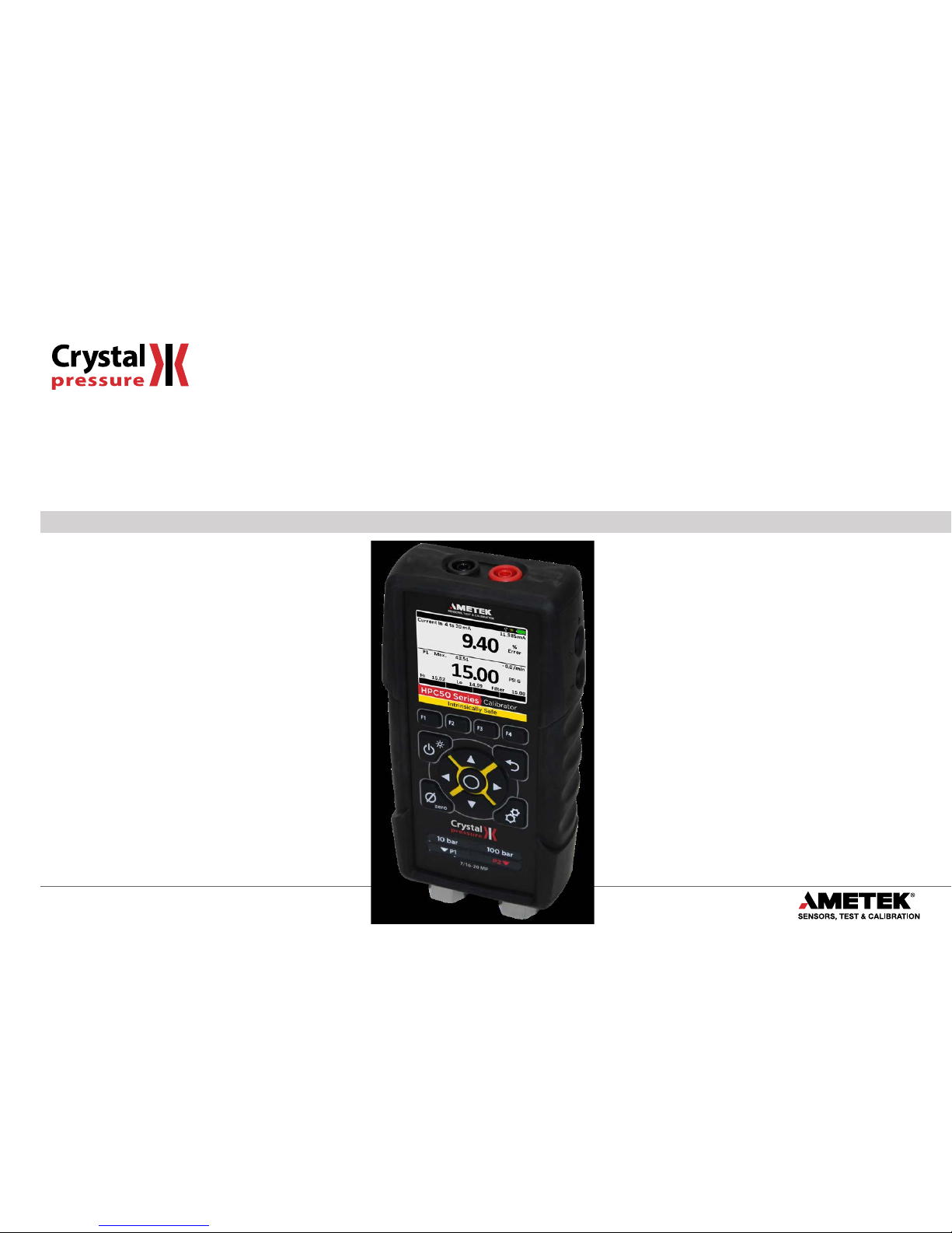
Ametek HPC50 Series User manual
Other Ametek Test Equipment manuals

Ametek
Ametek Teseq NSG 3150 User manual

Ametek
Ametek JOFRA STS-050 A/B User manual

Ametek
Ametek Chandler Engineering 4207D User manual

Ametek
Ametek Jofra ASC-400 User manual

Ametek
Ametek NSG 4070C User manual

Ametek
Ametek NB-3010 User manual

Ametek
Ametek JOFRA ASC300 User manual

Ametek
Ametek Teseq CDN 3153-S63 User manual

Ametek
Ametek PCD 8 S Series User manual

Ametek
Ametek CSC201 User manual

Ametek
Ametek LS2.5 Series User manual

Ametek
Ametek XP2i User manual

Ametek
Ametek NSG 4070C1 User manual

Ametek
Ametek TAYLOR HOBSON Surtronic S-100 Series User manual

Ametek
Ametek VERSITRON BT130S User manual

Ametek
Ametek PK II User manual

Ametek
Ametek Surtronic Duo User manual

Ametek
Ametek T Series User manual

Ametek
Ametek CS2-225 User manual

Ametek
Ametek JOFRA IPI Guide


Popular Test Equipment manuals by other brands


Redtech
Redtech TRAILERteck T05 user manual

Venmar
Venmar AVS Constructo 1.0 HRV user guide

Test Instrument Solutions
Test Instrument Solutions SafetyPAT operating manual

Hanna Instruments
Hanna Instruments HI 38078 instruction manual

Kistler
Kistler 5495C Series instruction manual

Waygate Technologies
Waygate Technologies DM5E Basic quick start guide

StoneL
StoneL DeviceNet CK464002A manual

Seica
Seica RAPID 220 Site preparation guide

Kingfisher
Kingfisher KI7400 Series Training manual

Kurth Electronic
Kurth Electronic CCTS-03 operating manual

SMART
SMART KANAAD SBT XTREME 3G Series user manual

Agilent Technologies
Agilent Technologies BERT Serial Getting started