Ampair 300 Manual

Date: 02 Feb 2011
Ampair ® 300 (Mk1, “Pacific”) Wind Turbine Manual
CD 2300
Issue: 1.2
Page 1 of 34
- 1 - © Ampair, April 2007
Ampair ® 300 Wind Turbine
Operation & Maintenance Manual

Date: 02 Feb 2011
Ampair ® 300 (Mk1, “Pacific”) Wind Turbine Manual
CD 2300
Issue: 1.2
Page 2 of 34
- 2 - © Ampair, April 2007
1INTRODUCTION.................................................................................................................................... 3
1.1 Labelling ........................................................................................................................................... 3
1.2 Applications ...................................................................................................................................... 3
2SAFETY INSTRUCTIONS ..................................................................................................................... 4
2.1 Disclaimer:........................................................................................................................................ 4
2.2 Potential sources of danger.............................................................................................................. 4
3TECHNICAL CHARACTERISTICS........................................................................................................ 7
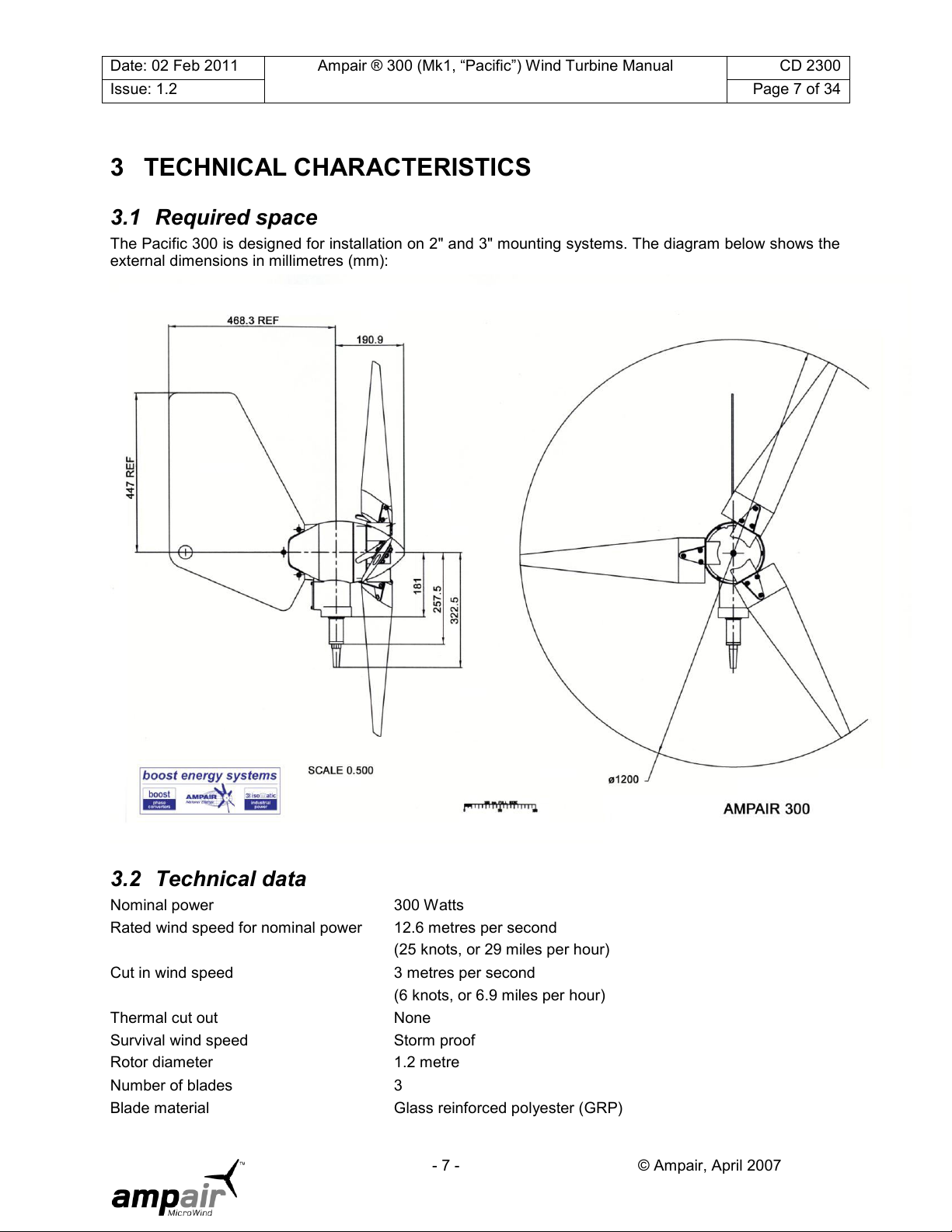
3.1 Required space ................................................................................................................................ 7
3.2 Technical data .................................................................................................................................. 7
3.3 System description ........................................................................................................................... 8
4INSTALLATION...................................................................................................................................... 9
4.1 Installation sequence........................................................................................................................ 9
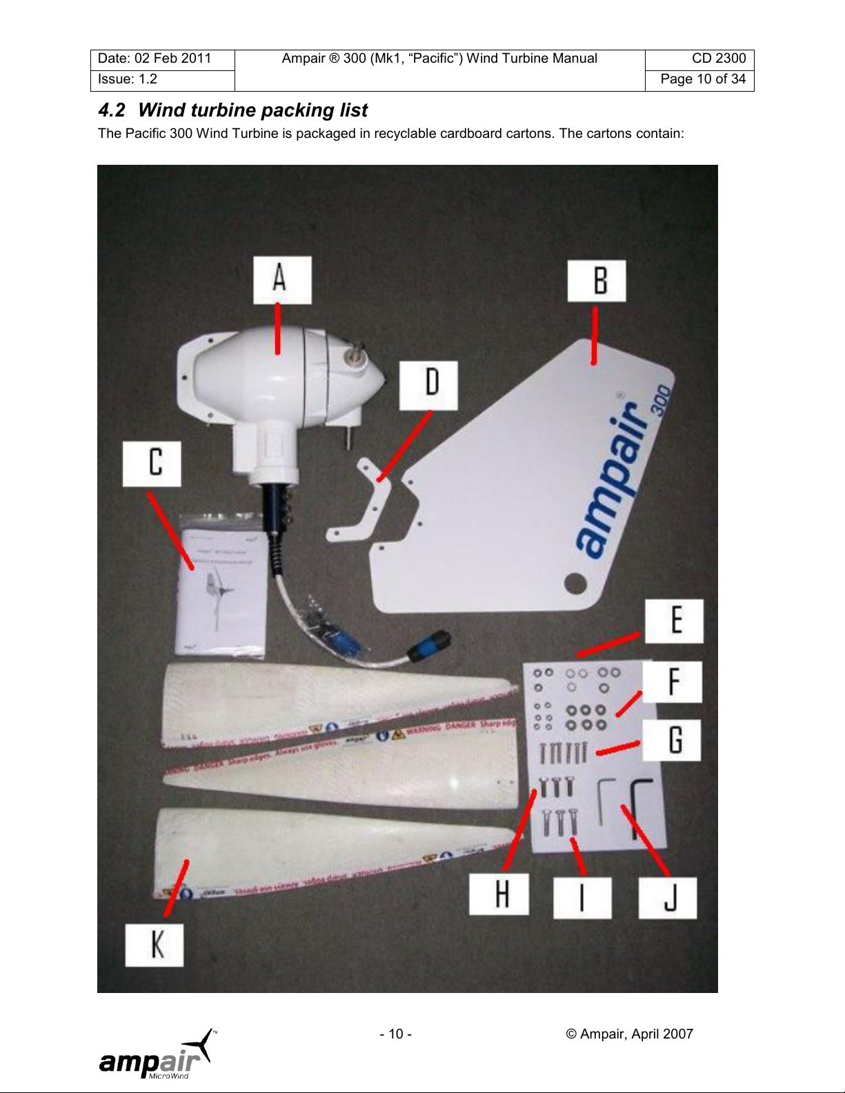
4.2 Wind turbine packing list................................................................................................................. 10
4.3Accessories packing lists................................................................................................................ 11
4.4 Tools ............................................................................................................................................... 12
4.5 Choosing a mounting...................................................................................................................... 13
4.6 Electrical installation ....................................................................................................................... 16
4.7 Electrical components .................................................................................................................... 19
4.8 Final assembly................................................................................................................................ 23
5OPERATION & PERFORMANCE........................................................................................................ 25
5.1 Starting and stopping...................................................................................................................... 25
5.2 Performance ................................................................................................................................... 26
6INSPECTION & MAINTENANCE......................................................................................................... 27
6.1 Major disassembly.......................................................................................................................... 27
6.2 Drawings and component list ......................................................................................................... 31
6.3 Recommended spares ................................................................................................................... 33
7WARRANTY......................................................................................................................................... 33
8SERVICING, REPAIRS, & DISPOSAL ................................................................................................ 33
Disclaimer:
The information in this manual is believed to be correct and reliable. However Ampair assumes no
responsibility for inaccuracies and omissions. The user of this information and product assumes full
responsibility and risk.
All specifications are subject to change without notice.
Wind turbines, electrical power and battery systems, and wind turbine mounting systems are all capable of
causing death or serious injury or fire if incorrectly installed, operated, or maintained. If in doubt, ensure
that all activities are carried out by trained and competent personnel.

Date: 02 Feb 2011
Ampair ® 300 (Mk1, “Pacific”) Wind Turbine Manual
CD 2300
Issue: 1.2
Page 3 of 34
- 3 - © Ampair, April 2007
1 INTRODUCTION
Thank you for purchasing an Ampair 300 wind turbine.
Ampair has been producing high quality wind turbines for over thirty years. The Pacific 300 is designed
and manufactured to give you many years of trouble free power generation. However, as with any other
wind turbine, reliable and effective operation will depend on where it is located and how it is assembled
and connected. Periodic inspection and maintenance is required. Furthermore there are safety hazards
associated with all wind turbines and this is why we ask that you read this manual carefully.
1.1 Labelling
This manual applies to the Ampair 300 manufactured by Ampair.
Ampair Energy Ltd
Unit 2 Milborne Business Centre, Blandford Hill
Milborne St Andrew, BLandford Forum, Dorset, DT11 0HZ
UK
Tel. +44 (0)1258 837 266
Fax. +44 (0)1258 837 496
Internet www.ampair.com
Email sales@ampair.com
Ampair™ is a business of Boost Energy Systems Ltd, manufacturers of distributed energy systems for fifty
years. Ampair™ and PowerFurl™ are trademarks of Ampair and Boost Energy Systems Ltd.
The label with the model type and nominal voltage
is on the electrical box cover where the name
Ampair is shortened to AMPAIR.
The serial number of the wind turbine is stamped
on the lower left side of the main body casting on
the outside of the tail fin flange.
1.2 Applications
The electrical power produced by the Pacific 300 wind turbine charges 12 volt or 24 volt DC batteries.
Alternating current (AC) electrical appliances can be supplied by connecting a 220/240 volt or 110 volt
inverter to the batteries.
For over thirty years wind turbines manufactured by Ampair have powered a wide variety of locations
including sailing yachts; remote houses; medical facilities; holiday homes; emergency shelters;
navigational aids; scientific and environmental monitoring stations; telecommunications systems; cathodic
protection systems; remote industrial locations; caravans and mobile homes; and increasingly are being
used to decrease dependence on centrally generated electricity in grid-connected homes, offices, and
commercial property.

Date: 02 Feb 2011
Ampair ® 300 (Mk1, “Pacific”) Wind Turbine Manual
CD 2300
Issue: 1.2
Page 4 of 34
- 4 - © Ampair, April 2007
Ampair recommends that most clients install wind turbines in combination with a proportionate amount of
solar photovoltaic panels (solar PV) as wind and solar power are highly complementary sources of
renewable, carbon neutral, non-polluting energy.
2 SAFETY INSTRUCTIONS
Please read this manual carefully before starting assembly and installation, or before conducting
maintenance. This manual provides information that is critical to ensuring your safety during assembly,
operation, and in case of trouble. If you have further questions please contact your dealer, an Ampair
service partner, or Ampair itself.
2.1 Disclaimer:
The information in this manual is believed to be correct and reliable. However Ampair assumes no
responsibility for inaccuracies and omissions. The user of this information and product assumes full
responsibility and risk.
All specifications are subject to change without notice.
Wind turbines, electrical power and battery systems, and wind turbine mounting systems are all capable of
causing death or serious injury or fire if incorrectly installed, operated, or maintained. If in doubt, ensure
that all activities are carried out by trained and competent personnel.
2.2 Potential sources of danger
Wind turbines are electrical machines with high speed rotating parts which are typically mounted at height.
Thus there are a variety of sources of potential hazards which can result in death or serious injury. These
dangers exist during installation, operation, or inspection and maintenance.
2.2.1 Mechanical dangers
The main dangers are the spinning rotor and the tail. The rotor blades are very sharp and can cause very
serious injuries even at low speeds.
WARNING:
Never touch the rotating rotor (the blades or hub).
Never try to stop the rotor by hand.
Do not mount the rotor where people or animals can reach the area swept by the rotor.
The rotor blades are made of glass fibre reinforced plastic and other composites. They are extremely
strong and are designed to withstand severe weather. However the blades may break if objects (e.g.
ropes, branches, clothing, flying ice, other debris) enter the rotor. If this happens the rotor will discharge
very sharp fragments of blade and debris at high speed. Also any items that become tangled in the rotor
(such as ropes) will whip around unpredictably and with great force.
WARNING:
Avoid any objects entering the rotor.
Never try to stop the rotor by throwing a rope or other object into it.
In order to maximise aerodynamic efficiency and to minimise sound levels the rotor blades‟ trailing edges
are very sharp. Handle these carefully and use gloves if necessary.
WARNING:
Use gloves when handling the rotor and blades.
The wind turbine is free to swivel about the pivot. This means that even when the rotor is stationary it can
swivel and the tail (or rotor) may hit anybody who has approached the machine. The machine will not
make a noise as it swivels and such a blow can be with great force and little warning (especially in gusty

Date: 02 Feb 2011
Ampair ® 300 (Mk1, “Pacific”) Wind Turbine Manual
CD 2300
Issue: 1.2
Page 5 of 34
- 5 - © Ampair, April 2007
wind conditions and/or on a boat). It will swivel extremely unpredictably if the rotor is fitted but the tail is
not fitted.
WARNING:
Prevent the machine swivelling before entering the radius of the tail and rotor.
Wear a safety helmet before entering the radius of the tail and rotor.
2.2.2 Electrical dangers
The generator can produce open circuit voltages of up to 60 volts ACrms (12 volt version) and 120 volts
ACrms (24 volt version) in the wiring run between the turbine and rectifier. This is in no load operation with
the stop switch in the „on‟ position and at a wind speed of approximately 30 miles per hour (approximately
15 metres per second).
WARNING:
Avoid handling bare open circuit wiring tails unless the rotor is physically stopped.
The charging current can reach up to 25 amps DC (12 volt version) and 12.5 amps DC (24 volt version) in
the wiring run between the rectifier and the battery (or load).
WARNING:
Install cables with sufficient cross sectional area of conductor. Inadequately sized cables
can rapidly overheat and create a fire hazard.
Install electrical components of sufficient voltage and current capacity at all points in the
circuit.
The battery must never be short circuited as the fault current is extremely high. If you do so there is a
serious risk that you will set the battery and cabling on fire, as well as releasing flammable and potentially
explosive gases (hydrogen) from the battery, and you will probably destroy the battery.
WARNING:
Never short circuit the battery.
Install fuses immediately adjacent to the wind turbine side of the battery (but not within
the battery compartment as the spark from a blowing fuse could ignite an explosive
hydrogen/air mixture).
Charging lead acid batteries releases flammable and potentially explosive hydrogen gas. Unsealed lead
acid batteries have vent caps to release this gas, which can detonate if it is mixed with air and a spark is
present (e.g. from a switch or a blowing fuse) or other ignition source (e.g. naked flame or hot surface
such as an exhaust).
WARNING:
Provide sufficient ventilation to the battery compartment.
Do not locate ignition sources within the battery compartment.
The regulators manufactured by Ampair are charge control regulators. However if you have chosen to
install (perhaps) cheaper and (definitely) less effective dump regulators then you should be aware that
these can become very hot. They must not be mounted on flammable surfaces.
WARNING:
Do not install dump regulators on or near flammable materials.
2.2.3 Dangers when mounting the wind turbine or working at height
Very careful attention must be given to the strength and integrity of the mounting. As a minimum this
should be capable of withstanding a peak horizontal load of 50 kg (100 lbs). If mounting the wind turbine

Date: 02 Feb 2011
Ampair ® 300 (Mk1, “Pacific”) Wind Turbine Manual
CD 2300
Issue: 1.2
Page 6 of 34
- 6 - © Ampair, April 2007
on a boat, note that the mounting has to withstand both the thrust from the wind, as well as the weight of
the turbine, and the inertial loads arising from vessel motions.
WARNING:
Only use adequately designed mounting systems.
A fall from the height at which a wind turbine is ordinarily mounted will often result in death or serious
injury. Therefore whenever practicable carry out as much work as possible on the wind turbine at deck or
ground level. If it is necessary to work on an installed wind turbine then use an appropriate access system
such as a mast that is designed to carry the load of a person; a „man-rated‟ winch or rope access system;
a hydraulic lift or other safe working platform. Wear appropriate safety equipment and make the general
working area as a tidy and safe as possible. If possible work during daylight on windless days (and in calm
seas if on a boat). Above all else think carefully about what you need to do and plan your work carefully,
have all the tools and equipment ready before you start, then brief all the members of the work team
thoroughly –including the actions in the event of an accident and/or injury.
WARNING:
Whenever possible work on the ground or deck, not at a height.
Use safety harnesses, safety helmets, and safety slings, etc.
Use „man-rated‟ lifting equipment and access systems
Work in daylight, on windless days (and in calm seas).
Keep the work area clear, plan your work, have your entire equipment ready, and brief
the team before starting the job.
Falling objects are potentially fatal. Do not step underneath hanging loads or folding/tilted masts. Make
sure that onlookers are kept back beyond the collapse radius of any masts. Ensure that any suspended
objects or tools are secured (e.g. by safety lanyards). Prevent onlookers from approaching (e.g. erect a
safety barrier and warning signs).
WARNING:
Secure any objects that might fall.
Do not go underneath hanging loads and the work area; wear safety helmets.
Keep onlookers at a safe distance.
When working on the wind turbine, especially when working at height, it is important to make sure it is first
electrically safe. Therefore prevent it generating (use the stop switch, turn it out of wind, and/or tie one of
the rotor blades to the mounting system or mast) and disconnect it from the battery system.
WARNING:
Disconnect all batteries and other power sources.
Prevent the generator from unintended starting.
Never approach the running rotor.

Date: 02 Feb 2011
Ampair ® 300 (Mk1, “Pacific”) Wind Turbine Manual
CD 2300
Issue: 1.2
Page 7 of 34
- 7 - © Ampair, April 2007
3 TECHNICAL CHARACTERISTICS
3.1 Required space
The Pacific 300 is designed for installation on 2" and 3" mounting systems. The diagram below shows the
external dimensions in millimetres (mm):
3.2 Technical data
Nominal power
300 Watts
Rated wind speed for nominal power
12.6 metres per second
(25 knots, or 29 miles per hour)
Cut in wind speed
3 metres per second
(6 knots, or 6.9 miles per hour)
Thermal cut out
None
Survival wind speed
Storm proof
Rotor diameter
1.2 metre
Number of blades
3
Blade material
Glass reinforced polyester (GRP)

Date: 02 Feb 2011
Ampair ® 300 (Mk1, “Pacific”) Wind Turbine Manual
CD 2300
Issue: 1.2
Page 8 of 34
- 8 - © Ampair, April 2007
Rotor speed
500-1400 rpm
Generator type
Permanent magnet, three phase with external rectifier
(rare earth neodymium magnets)
Nominal voltage
12 volt DC or 24 volt DC
Speed regulation
Blade pitch control above 13 metres per second
(27 knots, 30 miles per hour)
Power regulation
Blade pitch control above 13 metres per second
Brake
Generator short circuit (optional 'stop' switch)
Weight
12 kg
Housing
Die cast aluminium (powder coated)
Colour
White with red hub (other colours available on request)
Rotor thrust (at 20 metres per second)
160 Newtons
3.3 System description
The Ampair 300 is a wind driven generator (a wind turbine) capable of supplying up to 300 Watts of
electrical power at either 12 or 24 volts for charging batteries. A complete system includes the generator,
the rectifier, the field wiring, and normally a stop switch and a regulator, plus of course batteries and a
mounting.
3.3.1 The generator
The unit consists of a two part cast aluminium body, the two parts sealed by an "O" ring. One twelve pole
permanent magnet rotor runs on a stainless steel shaft. The shaft runs in two sealed grease-packed ball
bearings. One three phase stator is located within the body.
The three phase alternating current output of the stator passes to three carbon brushes mounted in brush
holders located behind the lower body section, accessible through the electrical cover plate. The carbon
brushes carry the output to three brass slip rings mounted on the stationary pivot shaft, allowing the
machine to rotate to follow the wind. The output is electrically isolated from the case.
The body is mounted on the pivot shaft where it runs on sealed grease packed ball bearings at the top
and a composite plain bearing at the base. The top bearing is captive in the body; the lower bearing is
located in the body by a stainless steel spiral retaining ring. The pivot section contains an "O" ring around
the lower bearing to body junction and a "V" seal where the pivot shaft passes through the lower bearing.
The pivot axis passes through the centre of gravity of the assembled machine. This is necessary to
ensure alignment into the wind in light breezes without undue spinning, and to allow the wind turbine to be
used on small boats.
The rotor disc and hub together make up the unique PowerFurl™ furling mechanism. The three cambered
and twisted glass reinforced polyester (GRP) moulded blades have been designed to be perfectly
balanced and aerodynamically and acoustically efficient. They are mounted on an aluminium hub (shaped
like a nose cone). The purpose of the PowerFurl™ furling mechanism is to simultaneously twist all three
blades along their axis when the wind speed becomes excessive, whilst still keeping the wind turbine
facing into the wind and generating power. The three special pitching weights form an integral part of the
PowerFurl™ mechanism. The hub is fitted to the generator shaft by an M10 cap screw.
The blades have a relatively broad root section to enable them to start up in low wind speeds. This is
important as for much of the time the wind only blows at low speeds. The blades are of a rigid construction
to minimise pulsating aerodynamic noise caused by blade deflection (fluttering)
An aluminium alloy tail vane is clamped to the rear of the generator body using three M8 x 25mm stainless
steel screws, six plain washers and three lock nuts. The tail vane is provided with a grab hole at its lower
corner to facilitate turning the unit cross-wind to stop the wind turbine rotating when required (e.g. using a
boat hook).
All Ampair 300 units are constructed of marine grade materials. All aluminium parts are alacromed and
powder coated inside and out, or anodised. All other parts are stainless steel or composite, except for
elastomers.

Date: 02 Feb 2011
Ampair ® 300 (Mk1, “Pacific”) Wind Turbine Manual
CD 2300
Issue: 1.2
Page 9 of 34
- 9 - © Ampair, April 2007
3.3.1.1 Low temperature operation
Plastic materials do not perform well in extreme cold, becoming brittle and breaking. This applies to wind
turbine blades, whether glass filled or not. Operation at around 0°C should not be a problem, but most
materials are vulnerable at –20°C and cannot be warranted to survive indefinitely. Ampair‟s glass filled
polyester blades are superior to nylon, carbon polymer or other plastics in this respect. However, when ice
factors are also considered, the prediction of blade reliability is even more difficult.
Other materials are also suspect. For this reason Ampair uses Neoprene components where possible and
"Arctic" grade PVC cables. Grease used in sealed bearings allows performance to –30°C or below, but
component tolerances (ball and ring) can lead to greater friction and increased wear causing reduced
bearing life.
3.3.2 The rectifier
It is best to transmit electrical power as AC at as high a voltage and as low a current as possible so as to
minimise losses due to the resistance of the wiring system. For this reason the rectifier of the Pacific 300
is not fitted inside the generator but is instead supplied as a separate unit for fitting adjacent to the
regulator and or battery. The rectifier is a three way bridge rectifier mounted on a heat sink.
3.3.3 Other system components
The basic wind turbine package only consists of the generator and rectifier. The other components which
can be linked together in a modular manner are described elsewhere in this manual.
4 INSTALLATION
4.1 Installation sequence
A lot of problems can be prevented if the following sequence is adhered to:
1. First check that your order is complete and undamaged, and that you have received the correct
voltage generator (12 or 24 volt). See the packing lists below to assist in this.
2. Gather your tool kit. See tool list below.
3. Plan your installation. See guidance notes below.
4. Mechanically install the mounting system.
5. Run the electrical wiring and mechanically mount any accessories (including the rectifiers on
their heatsink) but do not connect to the batteries.
6. Mechanically install the wind turbine generator, and then electrically connect it.
7. Connect to the batteries.
8. Check correct operation & installation.

Date: 02 Feb 2011
Ampair ® 300 (Mk1, “Pacific”) Wind Turbine Manual
CD 2300
Issue: 1.2
Page 10 of 34
- 10 - © Ampair, April 2007
4.2 Wind turbine packing list
The Pacific 300 Wind Turbine is packaged in recyclable cardboard cartons. The cartons contain:

Date: 02 Feb 2011
Ampair ® 300 (Mk1, “Pacific”) Wind Turbine Manual
CD 2300
Issue: 1.2
Page 11 of 34
- 11 - © Ampair, April 2007
A
1
pcs
Generator and hub
B
1
pcs
Tail fin
C
1
pcs
Operation manual
D
1
pcs
Tail fin pad
E
9
pcs
Tail fin mounting nuts and washers
F
6
pcs
Turbine blade mounting nuts and washers
G
6
pcs
Blade mounting bolts
M6 × 30 Hex Bolts
H
3
pcs
Tail fin mounting bolts (no pad)
M8 × 25 Bolts
I
3
pcs
Tail fin mounting bolts (with pad)
M8 ×35 Bolts
J
2
pcs
Allen keys
5mm and 6mm
K
3
pcs
Rotor blade
4.3 Accessories packing lists
4.3.1 Basic Pacific 300 stern mount kit (SMK)
The basic Ampair 300 Stern Mount Kit (SMK) carton contains:
A
1
pcs
Pole A, 800mm,
Four 6.5mm holes each end, two 10.2mm
holes centrally
B
1
pcs
Pole B, 800mm,
Four 6.5mm holes each end.
C
1
pcs
Pole C, 970mm,
25mm OD, strut pole,
D
2
pcs
Stay wires
Terminated by thimbles and "D" ring nuts.
E
1
pcs
Bag 1
Containing: yoke, two angle feet and
backstay clamp shell.
F
1
pcs
Bag 2
Containing: one anodised aluminium alloy
joiner tubes.
G
1
pcs
Kit 1: Strut, yoke & feet fixings
1 pcs M6 x 40mm screw
2 pcs M6 x 35 hex screw
3 pcs M6 shakeproof washers
3 pcs M6 Nyloc nuts
1 pcs M10 threaded rod 75mm
2 pcs M10 shakeproof washers
1 pcs M8 x 60mm hex bolt
2 pcs M8 plain washers
1 pcs M8 Nyloc nut
H
1
pcs
Kit 2: Joiner tube fixings
16 pcs M6 x 10mm screws
16 pcs M6 shakeproof washers
This arrangement, places the blade tips 2 metres (7 feet) above the base fixing. If there is a raised area
adjacent upon which people may stand, raise this base accordingly.
4.3.2 Pacific 300 mizzen bracket
The Ampair 300 Mizzen Bracket carton contains:
O
1
pcs
Bracket
P
2
pcs
threaded rod
Ml0 x 150mm threaded rod

Date: 02 Feb 2011
Ampair ® 300 (Mk1, “Pacific”) Wind Turbine Manual
CD 2300
Issue: 1.2
Page 12 of 34
- 12 - © Ampair, April 2007
Q
8
pcs
Nuts
MI0 nuts
R
8
pcs
plain washers
Ml0 plain washers
4
pcs
Shakeproof washers
MI0 shakeproof washers
4.3.3 Pacific 300 gantry mount
The Ampair 300 Gantry Mount carton contains:
O
1
pcs
Bracket
Pole with double welded base flange
4.3.4 Pacific 100 to Pacific 300 mounting adaptor
The Ampair 100 to Pacific 300 mounting adaptor bag contains:
O
1
pcs
Adaptor tube
Pole with female to male cross-over
4.3.5 Pacific 300 land mounting systems
Mounting systems are available for land use of the Ampair 300, but most users choose to fabricate their
own from local materials. See guidance notes further on, or ask Ampair if you wish to purchase a system
suitable for your site.
4.3.6 Pacific 300 basic regulator
The Ampair 300 Basic Regulator comes in two versions: the 12 volt or the 24 volt version. It is not
possible to convert these from one to the other. The carton contains:
A
1
pcs
Regulator
12 volt or 24 volt version
B
1
pcs
Operation manual
4.3.7 Pacific 300 advanced regulator
The Ampair 300 Advanced Regulator comes in only one version which can be configured for either 12 volt
or 24 volt use (by Ampair authorised dealers). The carton contains:
A
1
pcs
Regulator
Configurable
B
1
pcs
Operation manual
4.3.8 Pacific 300 stop (parking) switch
The Ampair 300 Stop Switch carton contains:
A
1
pcs
Stop (parking) switch
B
1
pcs
Operation manual
4.3.9 Fuse holder and fuses
The bag of fuse holders and fuses contains:
A
1
pcs
Fuse holder
For 30 Amp, slow blow
B
1
pcs
Fuse
30 Amp, slow blow
4.4 Tools
For installation of your Ampair 300 the necessary Allen keys are supplied. In addition to any specialist
tools required for locally fabricated mounting systems, the following general tools will also be helpful:
Screw drivers
Spanners
Wire strippers

Date: 02 Feb 2011
Ampair ® 300 (Mk1, “Pacific”) Wind Turbine Manual
CD 2300
Issue: 1.2
Page 13 of 34
- 13 - © Ampair, April 2007
Wire crimpers
Heat shrink and/or electrical tape
Multimeter
4.5 Choosing a mounting
Where and how to mount a wind turbine is critical. The consequences of selecting a poor location can be
unsafe operation, poor reliability, and low power output –or all three. As well as reading these guidance
notes, if in doubt please consult Ampair or your distributor for advice.
4.5.1 Siting land based units
The wind turbine should be sited as high as practicable, clear of windbreaks or buildings and away from
sources of turbulence. These conditions are shown diagrammatically below.
WARNING:
Before a wind turbine is installed in an excessively windy location, the operators must
satisfy themselves that the site is suitable. It may be necessary to log site wind speed
and direction data at various heights prior to installing the machine.
Any indication of turbulence means that the generator should be re-sited or raised above
the turbulence. Wind data must be from exactly where the turbine is to be sited, not
merely close by.
If possible avoid roof-top mounting which can give rise to turbulence, shock loads and
vibration. If roof-top mounting is selected then ask Ampair for a vibration-isolated
mounting system.
4.5.2 Mechanical installation of land based units
Free-standing installations should generally conform to the figure on the right. The main components are:

Date: 02 Feb 2011
Ampair ® 300 (Mk1, “Pacific”) Wind Turbine Manual
CD 2300
Issue: 1.2
Page 14 of 34
- 14 - © Ampair, April 2007
Mast: of steel tube (water pipe or scaffold tube), alloy
tube or wood (telegraph pole). If the guys are unsuitable
(grazing cattle or small children) then use a telegraph
pole one third buried, or a lattice tower as an expensive
alternative.
Guys: Usually galvanised steel wire protected by
plastic sheath and fitted with end thimbles. Don‟t use a
material that will stretch or deteriorate. Three equally
spaced guys (120°) will assist raising and lowering the
assembled mast. A high mast will require intermediary
guying: the top guys hold the mast upright, and the lower
guys prevent it from buckling.
The top fixing point for the guys should allow for minimum
overhang of the wind turbine generator, i.e. be only a
short distance below the wind turbine blade tips. This
prevents the top section of the mast from swaying too much.
Tensioners: These are the simple and easiest method of tensioning guys, but adjustment must be
uniform, since it is the guys that resist the thrust of the wind turbine. Do not over tension –a guy should be
snugly taut, but not drum tight.
Ground anchors: These should be suitable eyebolts fixed
in the ground and in line with the guys. Anchors in soft earth may
require concrete blocks or „dead men‟. Gravel or clay soils require
“auger” type anchors (see inset picture) and rocky ground may
need drilling and expanding rock anchors. Only the eye should be
visible above ground. Avoid waterlogged soils which have poor
holding properties. Install anchor below the frost level or
otherwise „frost heave‟ will eject them.
Base: This is to carry the weight of the generator and mast
only. Fixing again depends on the ground state but metal pegs
driven into soil are often sufficient. A lattice tower would need a
concrete base with expansion bolt fixings („rawlbolts‟). It is often
convenient to make a pivot arrangement for the base in-line with
one guy anchor to aid raising and lowering.
Lightning: Directly earth all metalwork. Bury output cables (minimum ½ metre depth) between mast
and battery position for better protection than suspending in air. Either run cabling through plastic conduit
or use a type specified for burying by local building or electrical codes.
4.5.3 Siting boat based units
There are four basic alternatives in the confined quarters of most small boats:
a) On a tall stayed pole on the stern of a boat (either the basic or the de luxe stern mount kit).
b) On a bracket on the mizzen mast of a yacht (mizzen bracket).
c) On a custom made welded „pushpit‟ structure, "A" frame, davit gantry etc. (gantry mount).
d) At the main or mizzen masthead of a yacht.

Date: 02 Feb 2011
Ampair ® 300 (Mk1, “Pacific”) Wind Turbine Manual
CD 2300
Issue: 1.2
Page 15 of 34
- 15 - © Ampair, April 2007
On a small boat space is at a premium and so the aim should be to get the wind turbine high up, away
from people on the busy deck. This has the advantage of placing the turbine up where the wind is
stronger, but has the disadvantage of adding top weight. Mast tops are generally the most congested
location on a boat and so these are seldom utilised as a mounting location, irrespective of top weight
considerations. On ketches (other than junk rigged ones) the mizzen mast provides a good location, but
for sloops stern pole mounts or stern gantry mounts are more typical compromises. The advantage of a
stern pole is that it can be de-rigged fairly easy (e.g. to put a boat into racing trim for a season) whereas
gantries are for committed cruisers and will also typically be designed as tender davits, aerial mounts, and
solar panel mounts.
Very careful attention must be given to the strength and integrity of the mounting. This should be capable
of withstanding a peak horizontal load of 140 kg (300 lbs). Bear in mind that the blades will flex slightly in
extreme weather conditions and so sufficient clearance must be left for this. The mounting should not rest
on a resonant surface such as the centre of a cabin roof since this may transmit any vibration making the
machine audible inside.
WARNING:
The mounting pole should be vertical.
The space between the blade tips and the mounting pole must be left clear, i.e. no
clamps or other items should diminish this clearance.
The pole base should be mounted where the structure is very rigid
4.5.4 Mechanical installation of Pacific 300 stern mount kit
a) Check. Ensure that a complete and undamaged set of parts has been received.
b) Pole position. The pole base fixing may be moved to one side provided that, when viewed from above,
the angle between the strut and either wire is greater than 45 degrees.
c) Pole assembly. Using the joiner tubes and M6 x 10mm screws and shake-proof washers, assemble the
poles so that pole A (holes in the middle) is the top pole, pole B (no holes in the middle) is the middle pole
and the Ampair pole becomes the bottom pole (two holes only at one end for fixing the feet).
A thread locking solution (e.g. Loctite 641) will stop screws shaking loose due to long term vibration. It
may be easier to feed the cable through the poles as they are assembled.
d) Feet. Using the M8 x 60mm bolt, washers and nut, fix the feet to the pole end and screw down the feet.
The feet should be arranged so the pole can pivot in line with the strut. This usually means aligned fore
and aft unless the pole is off-centre.
e) Stay Wires. Having assembled the poles with joiner tubes, site the pole and attach the two stay wires
with the yoke in place on the pole. Find suitable points for the stay wire base fixings, allowing for the fact
that these will be under considerable tension in use. "Bottle screws" are suggested as a tensioning
method.
f) Backstay strut. File the groove in the strut pole end and clamp shell to accommodate the backstay wire
diameter less 0.5mm. Cut the strut pole to length required. Drill the hole for the strut to yoke bolt in situ to
ensure correct orientation of holes. Ideally the strut should form a right angle with the backstay.

Date: 02 Feb 2011
Ampair ® 300 (Mk1, “Pacific”) Wind Turbine Manual
CD 2300
Issue: 1.2
Page 16 of 34
- 16 - © Ampair, April 2007
4.5.5 Mechanical installation of Pacific 300 mizzen bracket
The major load that the bracket has to withstand is one of torsion, hence the box section. At 100mm wide
this is close to the width of many mizzen masts and any slight difference can be accommodated by
bending the end plates to suit or by spacing with nuts and washers.
Drill through the end plates and mizzen and fit using the M10 fixings provided. Monel rivets are the best
attachment method for aluminium masts. Studs are best for wooden masts. If using studs on aluminium
masts then fit spacers so as not to crush the mast.
If there is any danger of running rigging becoming entangled in the wind turbine then install stays to keep
the turbine guarded.
4.6 Electrical installation
Electrical installation should only be performed by competent personnel who have studied this manual. If
in doubt ask Ampair.
First mechanically mount the main system components (except the wind turbine), then run the field
cabling, then make the connections, then install the wind turbine and connect to it. Only then connect to
the battery.
WARNING:
Do not assemble the generator, vane and turbine until the electrical installation is
completed
4.6.1 Wiring diagrams
4.6.1.1 Wiring diagram without regulator
rectifier
battery
+
-
stop
switch
fuse
ammeter
DC colour code:
Red = positive (+)
Black = negative (-)
Fuse sizing:
30 A for 12 V
15 A for 24 V
Block diagram
alternating current, AC
direct current, DC

Date: 02 Feb 2011
Ampair ® 300 (Mk1, “Pacific”) Wind Turbine Manual
CD 2300
Issue: 1.2
Page 17 of 34
- 17 - © Ampair, April 2007
4.6.1.2 Wiring diagram with regulator
battery
+
-
fuse
ammeter
DC colour code:
Red = positive (+)
Black = negative (-)
Fuse sizing:
30 A for 12 V
15 A for 24 V
stop
switch
rectifier*
*rectifier or integrated rectifier + regulator
(such as the S-12-300 and S-24-300)
Connection diagram
(rectifier or integrated
regulator + rectifier)
battery
+
-
rectifier
fuse
stop
switch
ammeter
*
DC colour code:
Red = positive (+)
Black = negative (-)
Fuse sizing:
30 A for 12 V
15 A for 24 V
regulator
Block diagram
* Ideally connect the ammeter between
the rectifier and the regulator.

Date: 02 Feb 2011
Ampair ® 300 (Mk1, “Pacific”) Wind Turbine Manual
CD 2300
Issue: 1.2
Page 18 of 34
- 18 - © Ampair, April 2007
battery
+
-
fuses
DC colour code:
Red = positive (+)
Black = negative (-)
Fuse sizing:
30 A for 12 V
15A for 24 V
stop
switch
rectifier /
heat sink
*separate rectifier and regulator such as NC25A used in single in / single out configuration
Connection diagram
(separate regulator and
rectifier)
ammeter
bat+
regulator
in+
sense-
sense+
battery
+
-
fuse
DC colour code:
Red = positive (+)
Black = negative (-)
Fuse sizing:
30 A for 12 V
15A for 24 V
stop
switch
rectifier /
heat sink
*separate rectifier and regulator such as PR-300 used in single in / single out configuration
Connection diagram
(separate regulator and
rectifier)
regulator
gen1+
gen2+
gen-
bat-
bat2+
bat1+
ammeter

Date: 02 Feb 2011
Ampair ® 300 (Mk1, “Pacific”) Wind Turbine Manual
CD 2300
Issue: 1.2
Page 19 of 34
- 19 - © Ampair, April 2007
If the Pacific 300 wind turbine is connected on the load side of the battery isolator switch, it may damage
electrical equipment. Under these conditions it is possible to run the wind turbine whilst the battery is
isolated, but this can subject the system to excess voltage.
WARNING:
Connect the wind turbine to batteries, not to loads.
4.7 Electrical components
4.7.1 Wiring
After deciding where the wind turbine is to be mounted measure the length of the wiring that will actually
run to the battery in both the AC section (the three wire section from the turbine to the rectifier) and the
DC section (the two wire section from the rectifier to the battery). Then select the minimum cross sectional
area per cable from the table below. Wherever possible locate the rectifier as close to the battery so as to
minimise the DC cable length and to maximise the AC cable length.
Minimum AC cable size for 12 volt wind turbine:
Total AC section length
Up to 8 m
Up to 27 ft
8 to 12 m
27 to 40 ft
12 to 18 m
40 to 60 ft
18 to 30 m
60 to 100 ft
30 to 50 m
100 to 166 ft
30 to 76 m
166 to 253 ft
76 to 100 m
253 to 333 ft
Minimum cross sectional
area per cable
2.5 mm2
14 AWG
4 mm2
12 AWG
6 mm2
10 AWG
10 mm2
8 AWG
16 mm2
6 AWG
25 mm2
4 AWG
35 mm2
2 AWG
Minimum DC cable size for 12 volt wind turbine:
Total DC section length
Up to 5 m
Up to 16 ft
5 to 10 m
16 to 32 ft
10 to 18 m
32 to 60 ft
18 to 28 m
60 to 90 ft
28 to 44 m
90 to 145 ft
44 to 68 m
145 to 220 ft
68 to 110 m
220 to 360 ft
Minimum cross sectional
area per cable
4 mm2
12 AWG
6 mm2
10 AWG
10 mm2
8 AWG
16 mm2
6 AWG
25 mm2
4 AWG
35 mm2
2 AWG
50 mm2
1 AWG
Minimum AC cable size for 24 volt wind turbine:
Total AC section length
Up to 8 m
Up to 27 ft
8 to 12 m
27 to 40 ft
12 to 18 m
40 to 60 ft
18 to 30 m
60 to 100 ft
30 to 50 m
100 to 166 ft
30 to 76 m
166 to 253 ft
76 to 100 m
253 to 333 ft
Minimum cross sectional
area per cable
1.5 mm2
16 AWG
2.5 mm2
14 AWG
4 mm2
12 AWG
6 mm2
10 AWG
10 mm2
8 AWG
16 mm2
6 AWG
25 mm2
4 AWG
Minimum DC cable size for 24 volt wind turbine:
Total DC section length
Up to 5 m
Up to 16 ft
5 to 10 m
16 to 32 ft
10 to 18 m
32 to 60 ft
18 to 28 m
60 to 90 ft
28 to 44 m
90 to 145 ft
44 to 68 m
145 to 220 ft
68 to 110 m
220 to 360 ft
Minimum cross sectional
area per cable
2.5 mm2
14 AWG
2.5 mm2
14 AWG
4 mm2
12 AWG
6 mm2
10 AWG
10 mm2
8 AWG
16 mm2
6 AWG
25 mm2
4 AWG
WARNING:
Insufficient cross sectional area of conductor will cause the cable to heat up and create a
fire hazard all along the cable, at the same time.
WARNING:
Always use tinned stranded conductors for best corrosion protection on boats.
WARNING:
Connect with the correct polarity. When wiring the DC system be aware that if the wind
turbine is connected to the battery by the reverse polarity the output rectifiers may be
destroyed or the internal soldered connections to the brush holders may melt. Check and
double-check DC polarity before final connection.
BROWN or RED = + Positive

Date: 02 Feb 2011
Ampair ® 300 (Mk1, “Pacific”) Wind Turbine Manual
CD 2300
Issue: 1.2
Page 20 of 34
- 20 - © Ampair, April 2007
stop
switch
Connection diagram
(stop switch)
BLUE or BLACK = - Negative (YELLOW is preferred colour in the USA)
When mounting the Ampair 300 on its mounting pole or bracket, the cable needs to be fed down through
the mounting. When arranging this cable make sure it cannot chafe at the point where it leaves the
mounting pole. Either lead the cable out of the bottom of the pole in a gentle curve or, drill an exit hole in
the pole large enough to take a rubber grommet to protect the cable from the sharp edges of the hole.
In marine environments cables with tinned multi-strand conductors are recommended to prevent salt air
corrosion which will otherwise cause substantial performance reductions in a short time.
Wiring between the generator (or junction box, connector, etc.) and the battery area should be clipped at
regular intervals to the structure for safety and a neat job.
On boats, to carry power from the Ampair to internal wiring we recommend that a good quality water-tight
connector be fitted
Cable hanging inside masts can be quite heavy. We recommend fitting a strain relief at the top so that the
weight is not carried by the wind turbine. Arrange this strain relief so that if the cable is disconnected from
the wind turbine (so as to remove the wind turbine for maintenance) then the end of the cable can be
secured and not fall down inside the mast.
If there is any danger of the cable „slatting‟ noisily inside a hollow mast, then place some closed cell foam
pipe insulation over it as anti-slatting collars.
Maintain a consistent colour scheme throughout the cable runs, and mark line ends with a positive (+) and
negative (-) symbol to minimise risk of errors. At different times and in different countries the colour
schemes used in wiring systems have varied. If reusing old cable runs the only way to be sure is to
carefully trace all the cables and „loop test‟ them yourself during initial installation,
4.7.2 Fuses and circuit breakers
Fuses or miniature circuit breakers (MCBs) should always be fitted. The simplest possible arrangement
feeds the power from the Ampair directly to the battery via an in-line fuse in the positive line near to the
battery.
WARNING:
Always install a fuse. The fuse should be next to the battery terminal since, in the event
of a fault or damage to the cable, the battery will supply the fault-current.
Do not place the fuse inside the battery compartment itself as, in the event of a build up
of explosive hydrogen/air mixture in the battery compartment, the spark from a blowing
fuse could provide the detonation source.
4.7.3 Parking (stop) switch
We recommend installing a „stop‟ switch which
should be more correctly thought of as a
„parking‟ switch. Just as the parking brake in a
car should not be relied on to stop a car at high
speed, so the parking switch of the Ampair wind
turbine should not be relied on to stop the rotor
disc in high winds. Instead it is best to apply it
before the arrival of very high winds, or if
needing to ensure that the rotor does not move
in low winds (e.g. when approaching the rotor for
maintenance).
The switch should be wired as shown in the
diagram above. If wired in this way the wind
turbine will be stopped with the switch in the
„ON‟ or „1‟ position, and will run normally with the
switch in the „OFF‟ or „0‟ position. IMPORTANT NOTE: The „stop‟ switch is only to be used for stopping
the turbine in order that it can be inspected or to carry out maintenance. In the event of high winds the
Table of contents