Amperes EP1200A User manual

instruction manual
version 1/2013
EP1200A
Emergency Paging Microphone Panel
www.ampereselectronics.com

amperes
amperes electronics
PAGE 2
Thank you
for choosing another quality product from Amperes Electronics.
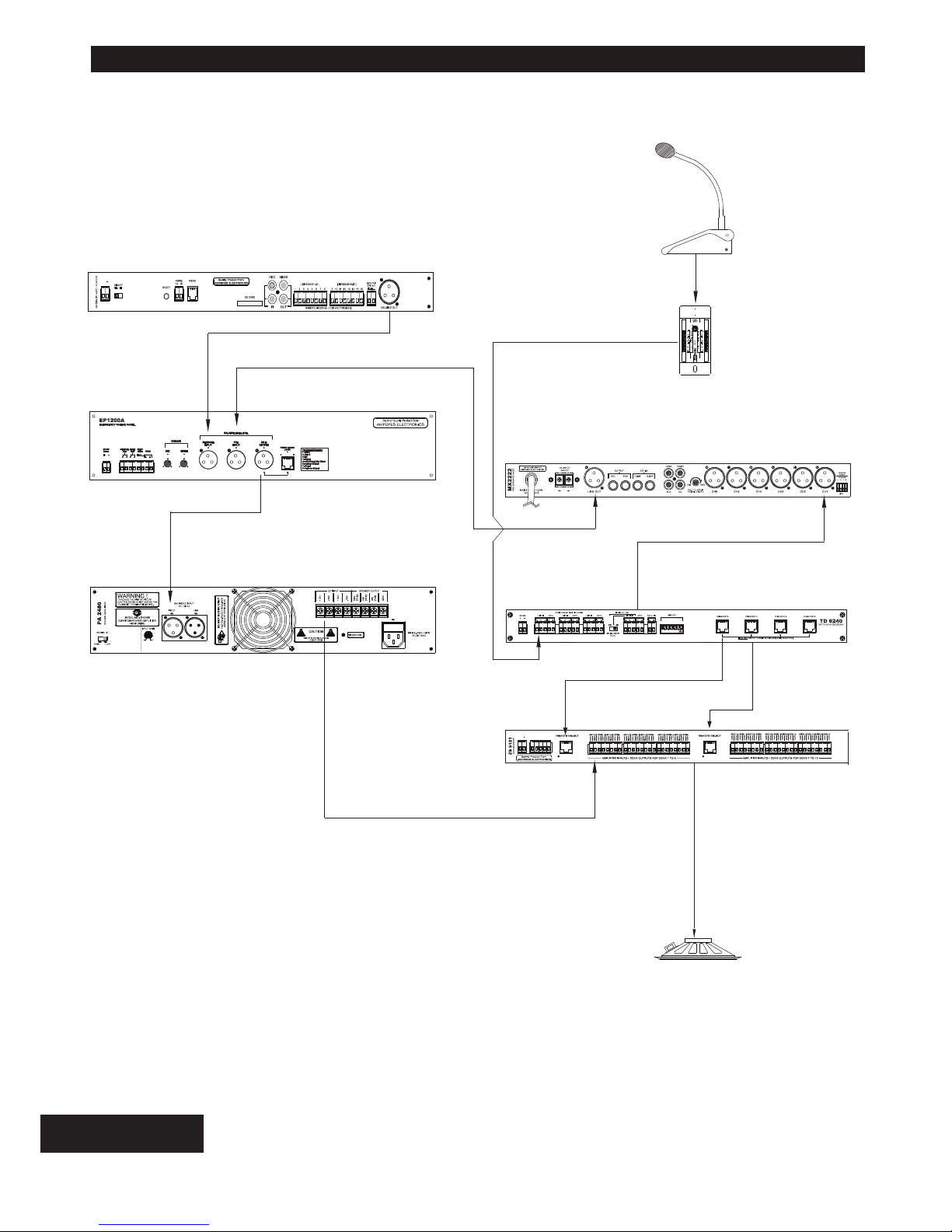
EP1200Ais enhanced version with RS485 data output, enabling the unit to be used together with iPX5150 IP
client for LAN based PASystem. Emergency paging and siren activation shall be available throughout the
entire network from main rack. Other local features shall remain as EP1200, but with improved audio quality.
Extra feature available from EP1200A is the availability of a dry contact, which is activated whenever the unit is
triggered. This allows connected to volume controller for overriding purpose.
We believe that this product shall be able to meet your demanding requirement with affordable pricing and
uncompromised features and quality. Though it is rather simple in the installation works, a brief read through
the manual is recommended and we are confident that you are getting a product of excellence.
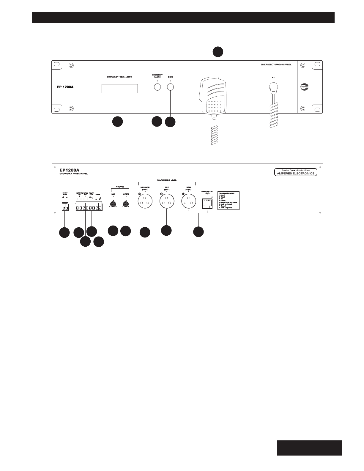
2. Built In Siren Tone Generator
The built in siren tone generator can be activated via the front panel test switch as well as remote triggering
switch. Its continuous 8 KHz tone shall be active for approximately 10 seconds when the switched is pressed
and shall cut off thereafter.
3. Visual FIRE Indicator
The front FIRE indicator shall lit when the siren is activated, or when the emergency paging microphone is
switched on. The bright flashing alert shall also lit when the remote siren port is triggered.
4. External Voice Message Activation
External voice recorder can be connected to EP1200A, instead to preamplifier mixer to allow prioritized
message broadcast over the BGM or normal paging sources. The activation of this playback shall require a
voltage free triggering which is available at the rear of the unit.
5. Priority Front Panel Microphone Paging
The front panel microphone is accorded the highest priority in paging, thus bypassing any available input
sources. This is important that emergency broadcast is not interfered when this announcement is made.
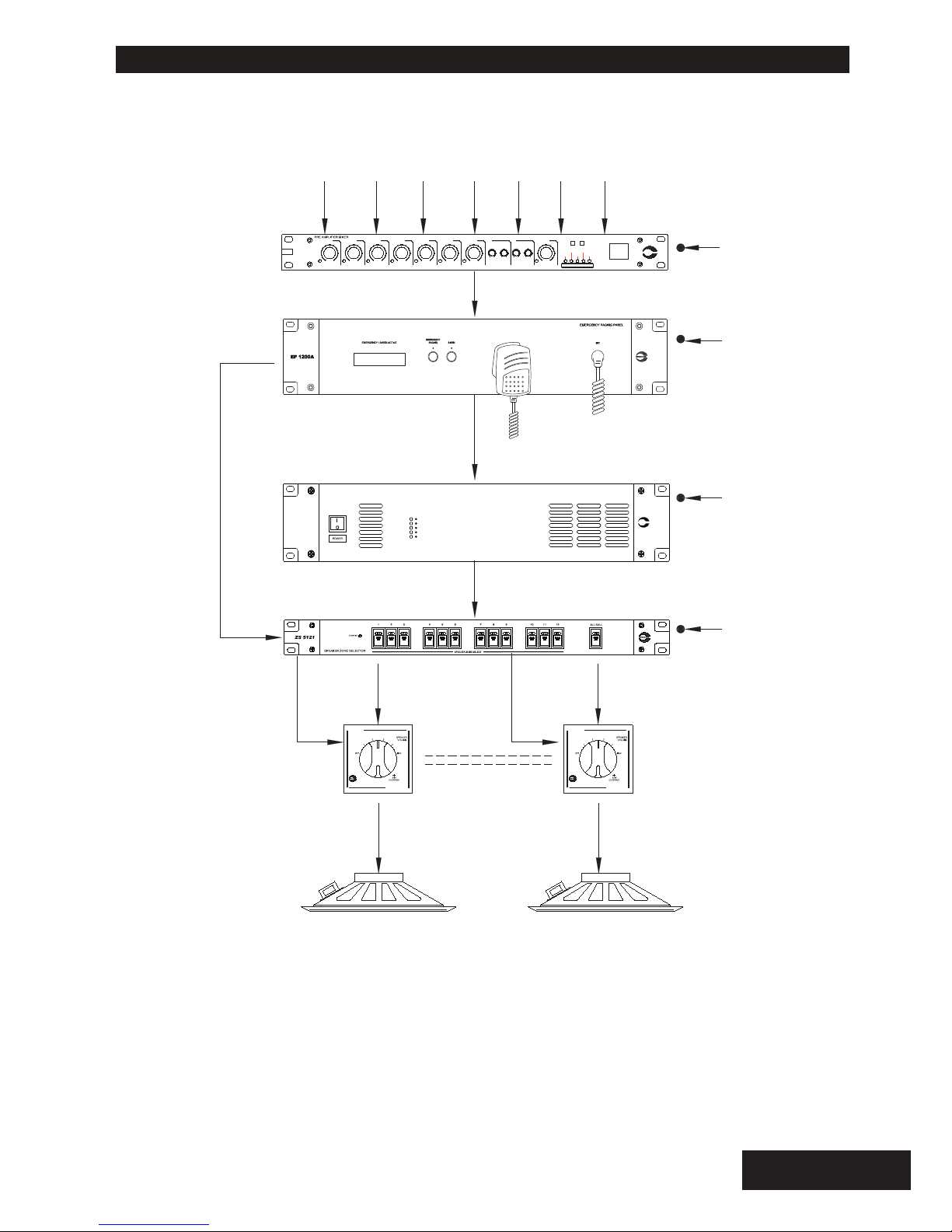
6. Aux Dry Contact for ALL CALL / E/M 24V Overriding Signal
When paging microphone or the siren is activated, it shall trigger an internal relay which provide a dry contact.
This can be used to switch on ALL CALL feature of the speaker zone selector as well as sending a 24V
emergency overriding signal to bypass volume controllers' attenuation. Proper configuration is required to
utilize this feature.
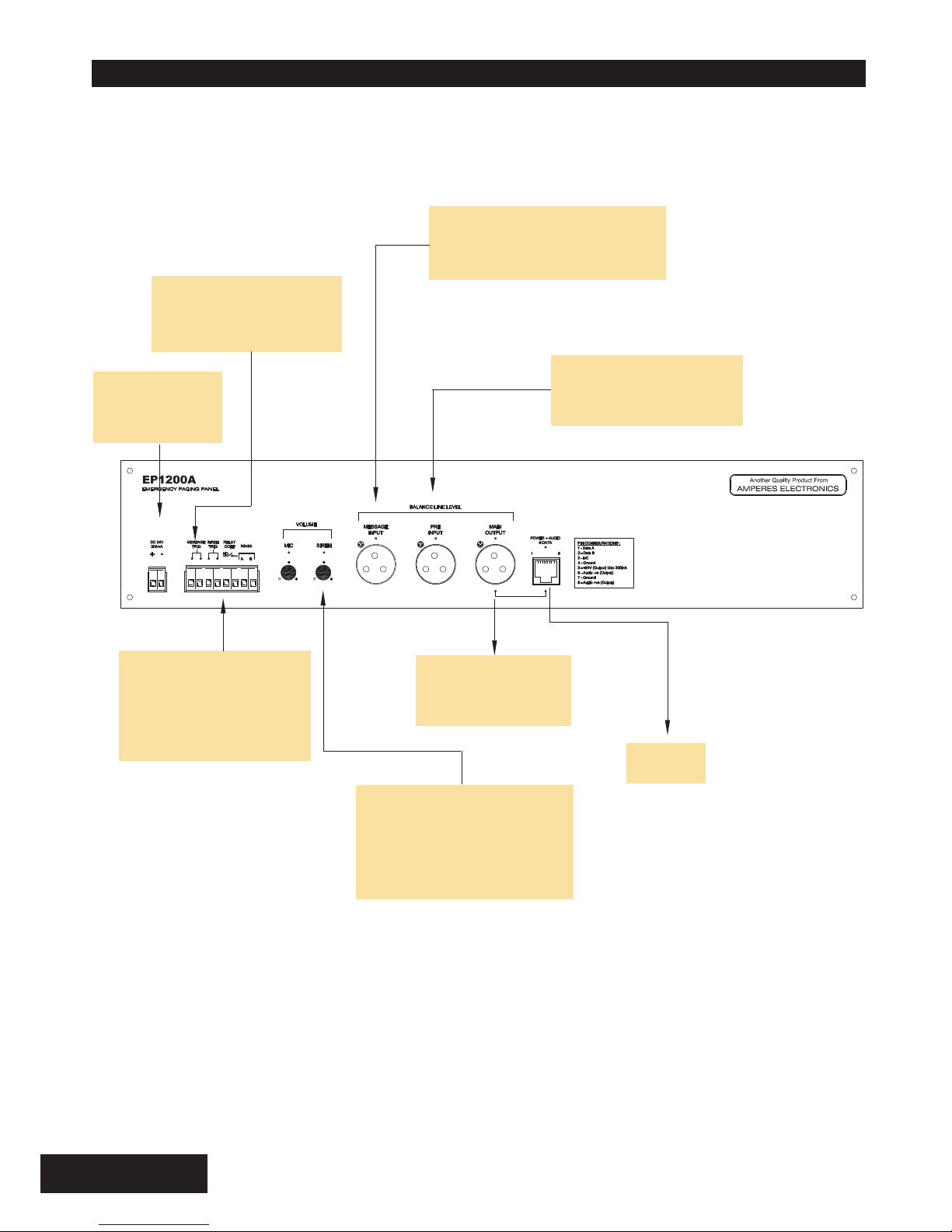
1. RS485 Data Output
The Data out are available in RJ45 or terminal connections. The RJ45 connection would enable direct play in
to IP Client for IP System setup, which includes the audio output and RS485 data in a single connector.
Summary of Features

PAGE 3
amperes electronics
FRONT VIEW
REAR VIEW
123
5
4
FIRE
6789
10 11 12 13 14
1. FIRE INDICATOR
2. EMERGENCY PAGING
This EMERGENCY PAGING button shall active all microphone as well as sending emergency paging mode to
other related equipment.
3. SIREN SWITCH
4. HANDHELD PAGING MICROPHONE
Pressing the microphone switch shall have priority over other inputs such as Siren, External Message input as
well as normal paging or BGM feeds. This shall also activate a dry contact, which can be used to activate ALL
CALL at speaker zone selector and 24V DC E/M overriding signal.
Press the siren button shall activate the siren which is momentary. FIRE indicator shall lit and the MIC switch
relay (item 7) shall close. Release of the switch shall deactivate the siren, Pressing it continuously shall activate
the unit for about 10 seconds, after which the unit shall reset.
Whenever siren or external activation device is triggered, the FIRE indicator shall flash alongside with siren
audio broadcast.
Parts Identifications

amperes electronics
PAGE 4
5. 24V INPUT
The unit operates on 24V DC. It is preferred that the unit to be supplied directly from the uninterrupted
power source. ie. Back up batteries. Alternatively, connect it to a regulated power supply unit which is
in turned has back up supply.
8. RELAY CONTACT
Triggering the front panel mic switch shall activate an internal relay. This ports provide a dry contact
which can be used to connect E/M overriding signal or to activate ALL CALL at speaker zone selector.
The recommended rating for the contact is 3A. In case higher rating is required, please use external
relay or contactor to accomodate the high current requirement.
7. REMOTE TRIGGER PORT FOR SIREN
External sensor device such as heat detector or fire alarm interface device can be connected to this
unit to activate the siren. The external device or switch must be voltage free to avoid damage to the
unit. Siren activation shall be approximately 10 seconds, afterwhich another contact is required to
broadcast the siren.
6. EXTERNAL MESSAGE TRIGGER PORT
External message player can be linked to it and can be broadcasted to the speakers when this port is
triggered. A voltage free contact is recommended to trigger the message playback.
10. HANDHELD MIC LEVEL CONTROL
This is to adjust the front paging mic volume. It is recommended that the setting is made during testing
and commissioning works.
11. SIREN OUTPUT LEVEL CONTROL
Adjust the siren output to an optimum level during testing and commissiong works.
12. EXTERNAL MESSAGE AUDIO INPUT
The external message playback signal shall be balanced line level.
13. PRE-AMPLIFIER INPUT JACK
Output from pre-amplifier mixer (balanced line level ) is connected to the unit which is normally closed
when the unit is not activated. Triggering the panel shall bypass the signal to allow higher priority audio
to the PA system.
14. DATAAUDIO OUTPUT
Audio output from the decoder is balanced line output level. RJ45 connector consists of audio, data and
power with the following pin configuration:-
Pin 1 - Data A
Pin 2 - Data B
Pin 3 - Relay Trigger Signal
Pin 4 - NC
Pin 5 - +24V Supply
Pin 6 - Audio -ve output
Pin 7 - Ground
Pin 8 - Audio +ve Output
9. RS485 PORT
External controls or interface devices shall be able to communicate with the unit. It shall be able to
communicate with software using RS485 to USB converter which shall be available in near future.
Parts Identifications

PAGE 5
amperes electronics
amperes
POWER
OFF SELECT
TUNER CD CASS
OFF
MASTER
MUSIC SOURCE
SIG IN
BASS MAXMIN
EXT INPUT
MAX MAXMIN
SOURCE
MIN
SIG IN
CHIME MIXER TREBLE
MAXMIN
TONE CTRL
CH5 CH6CH4
SIG INSIGIN SIG IN
MAXMIN MAXMIN MIN
CH3CH1 CH2
SIG INSIG IN
MAXMIN MAXMIN MAXMIN MAX
AUX
2222
MX
SIG IN
FIRE
PUBLIC ADDRESS POWER AMPLIFIER
SIGNAL -40 dB
SIGNAL -10 dB
POWER
PROTECT
CLIP
PA 2480
amperes
INPUT SOURCES (PAGING MICS, BGM PLAYERS ETC)
24V DC SUPPLY
24V DC BACK UP
24V DC SUPPLY
24V DC SUPPLY
MX2222 PRE-AMP
MIXER
EP1200A EMERGENCY
PANEL
POWER AMPLIFIERS
ZS SPEAKER
ZONE SELECTOR
SPK VOLUME
CONTROLLERS
SPEAKERS
audio out - balanced
100V line audio output
100V line output
24V E/M
override
24V E/M
override
100V line output
dry contact to
activate ALL
CALL and 24V
E/M override
signal
Schematic Diagram

amperes electronics
PAGE 6
24V DC POWER
SUPPLY / BACK
UP SUPPLY
TRIGGERING PORT TO
ACTIVATE EXTERNAL
PLAYBACK DEVICE
EXTERNALAUDIO INPUT
(BALANCED LINE SIGNAL) FROM
MESSAGE PLAYBACK DEVICE
OUTPUT FROM
PRE-AMPLIFIER MIXER
(BALANCED LINE LEVEL)
TO POWER
AMPLIFIER INPUT
(BALANCED LINE)
EXTERNAL SIREN
ACTIVATION CONTACT
(VOLTAGE FREE) ie.
FIRE CONTROL CENTER
/ SMOKE DETECTORS,
ETC
DRY CONTACT
(NORMALLY OPEN)
CONNECT TO ZONE
SELECTORS FOR E/M
OVERRIDING SIGNAL
ACTIVATION RS 485
Connecting The Unit

PAGE 7
ER1108 E/M
Override Panel
EP1200A Emergency Paging
Panel
Zone 2 Amplifier
Zone 5 Amplifier
Amplifier
Zone 1
Speakers
Zone 8
Speakers
BGM 2
An othe r Qu ality P rod uct F rom
OU TPU T 4 OUT PUT 3 OU TPU T 2 OUT PUT 1OU TPU T 5OU TPU T 6OU TPU T 7OU TPU T 8
INPU T 4 INPU T 3 INP UT 2 INPUT 1INPU T 5INPU T 7INPU T 8 INPU T 6
PRIORITY INPUT
Zone 3 Amplifier
Zone 4 Amplifier
Zone 7 Amplifier
Zone 8 Amplifier
Zone 1Amplifier
MxP2188
MR1300
Zone 6
amperes electronics
Connection the Unit - Matrix Paging Unit Installation

amperes electronics
PAGE 8
INPUT
OUTPUT
PIN 8 -COM
PIN 7 -24V
PIN 6 -Z6
PIN 5 -Z5
PIN 4 -Z4
PIN 3 -Z3
PIN 2 -Z2
PIN 1 -Z1
PIN 8 -COM
PIN 7 -24V
PIN 6 -Z12
PIN 5 -Z11
PIN 4 -Z10
PIN 3 -Z9
PIN 2 -Z8
PIN 1 -Z7
+
DC 24V CON
RLY
TRIG
RLY
PR
ZS
MX2222
EP1200A
PA2480
EX2800
TD6240
ZS5121
PD2800
Speaker
MR 1300
DC 24V
+
MR1300
Audio
Audio
RS485 & Audio
AMP Output
Audio
Cat5
Cat5
Connection the Unit - Conventional System

PAGE 9
amperes electronics
iPX5150
+12V
DC IN ON/OFF OUT
AUDIO 10BASE-T
ETHERNET RESET +A -B
RS485 RS232
ETHERNET / IP ADAPTER
ETHERNET ADDRESS :
ETHERNET SUBNET :
ETHERNET GATEWAY:
POWACT1
amperes
iPx5150
IN
ACT2
iPX5150
+12V
DC IN ON/OFF OUT
AUDIO 10BASE-T
ETHERNET RESET +A -B
RS485 RS232
ETHERNET / IP ADAPTER
ETHERNET ADDRESS :
ETHERNET SUBNET :
ETHERNET GATEWAY:
POWACT1
amperes
iPx5150
IN
ACT2
LAN
DC V
+
-
ON/OFF 10BASE-T
ETHERNET RS232
12V-24V
ETHERNET PAGING MANAGEMENT SERVER
ETHERNET ADDRESS : ETHERNET SUBNET : ETHERNET GATEWAY :
amperes
iPx 5100
MAC ADDRESS :
SERIAL NO :
RESET
Quality Product From
AMPERES ELECTRONICS
iPX5100
iPX5150
+12V
DC IN ON/OFF OUT
AUDIO 10BASE-T
ETHERNET RESET +A -B
RS485 RS232
ETHERNET / IP ADAPTER
ETHERNET ADDRESS :
ETHERNET SUBNET :
ETHERNET GATEWAY:
POWACT1
amperes
iPx5150
IN
ACT2
PIN 8-COM
PIN 7-24V
PIN 6-Z 6
PIN 5-Z 5
PIN 4-Z 4
PIN 3-Z 3
PIN 2-Z 2
PIN 1-Z 1
PIN 8-COM
PIN 7-24V
PIN 6-Z 12
PIN 5-Z 11
PIN 4-Z 10
PIN 3-Z 9
PIN 2-Z 8
PIN 1-Z 7
+
DC 24V CON
RLY
TRIG
RLY
PR
ZS
EP1200A
PD2800
MX2222
PA2480
ZS5121
TD6240
Speaker
Cat5
Cat5
Cat5
Cat5
Audio Output
RS485 (AB) Data
Cat5
Audio
AMP Output
Cat5 Cat5
Connection The Unit - IP Based Unit Installation

amperes electronics
PAGE 10
EP1200A
PIN 8-COM
PIN 7-24V
PIN 6-Z6
PIN 5-Z5
PIN 4-Z4
PIN 3-Z3
PIN 2-Z2
PIN 1-Z1
+
DC 24V CON
RLY
TRIG PR
ZS
EP1200A
PS9400 PSU
PM Series
Paging MIc
ZS5121 Zone Selector
Volume Controller
To Speakers
Fr. Zone Selector 100V
Line Output
24V E/M
Overriding
Signal
Connect this to allow
EP1200A to trigger
internal relay of Zone
Selector
Power requirement 24V DC
Power consumption 3.5W
MICROPHONE
Mic sensitivity -72 dB Omni directional
Impedance 600 Ohm
Frequency response 300 ~ 8 KHz
SIREN
Siren frequency Continuous at 8 KHz
Siren duration Continuous when activated
Siren activation Front test switch / remote contact
Input channel Pre-amplifier output, message recorder
Output level Balanced line out (1.2V)
Priority sequence Paging mic - siren - message - pre amp in
Indicators Front FIRE with backlight illumination
Dimension (WxHxD) 482 x 88 x 180 mm
Weight 3.0 kg
+-
Configuring ALL CALL and E/M Overriding
Technical Specifications

PAGE 11
Only Amperes Electronics Service Centres are allowed to make warranty repairs : a list of Amperes
Electronics Service Centres may be asked for by the purchaser or send directly to Amperes Electronics Sdn
Bhd at 70 Jalan Industri PBP 3, Tmn Perindustrian Pusat Bandar Puchong, 47100, Puchong, Selangor,
Malaysia or its authorized master distributor, Amperes Global Marketing. This warranty is not valid if repairs
are performed by unauthorized personnel or service centres.
This warranty covers only repairs and replacement of defective parts ; cost and risks of transportation as
well as removal and installation of the product from the main system are for the account of the purchaser.
This warranty shall not extend to the replacement of the unit.
This warranty does not cover damages caused by misuse, neglect, accident of the product as well as using
the product with power supply voltage other than shown on the product, or any other power supply source /
adaptor not recommended by the manufacturer.
This warranty does not cover damages caused by fire, earthquakes, floods, lightning and every cause not
directly related to the unit.
This warranty does not include any indemnity in favor of the purchaser or the dealer for the period out of
use of the unit; moreover the warranty does not cover any damages which may be caused to people and
things when using the product.
This warranty certificate is valid only for the described product, and is not valid if modifications are made on
this certificate or on the identification label applied on the product.
This warranty covers all the material and manufacturing defects and is valid for a period of 12 months from
the date of purchase or for a longer period in countries where this is stated by a national law. In this case,
the extension is valid only in the country where the product is purchased.
Amperes Electronics Sdn Bhd is not obliged to modify previously manufactured products under warranty if
the design changes or improvements are made.
Information contained in this manual is subject to change without prior notice and does not represent a
commitment on the part of the vendor. AMPERES ELECTRONICS SDN BHD shall not be liable for any
loss or damages whatsoever arising from the use of information or any error contained in this manual.
It is recommended that all services and repairs on this product be carried out by AMPERES
ELECTRONICS SDN BHD or its authorized service agents.
AMPERES series must only be used for the purpose they were intended by the manufacturer and in
conjunction with this operating manual.
AMPERES ELECTRONICS SDN BHD cannot accept any liability whatsoever for any loss or damages
caused by service, maintenance or repair by unauthorized personnel, or by use other than that intended by
the manufacturer.
By :
AMPERES ELECTRONICS
www.ampereselectronics.com
Made In Malaysia
amperes
Warranty Conditions
Disclaimer

Another Quality Product From
Amperes Electronics Sdn Bhd
Co Reg : 509025-X
www.ampereselectronics.com
This product has been manufactured under strict
ISO9001 : 2008 management system
Certificate no: 16895 / A / 0001 / UK / En
ISO 9001: 2008
Design & Manufacture of Public Address Equipment and Systems
Certicate No. 16895 / A / 0001 / UK / En
EP1200A
EMERGENCY PAGING PANEL
Table of contents
Other Amperes Microphone manuals

Amperes
Amperes PD1900 User manual

Amperes
Amperes PM1060 User manual

Amperes
Amperes PD1280 User manual

Amperes
Amperes PD1240 User manual

Amperes
Amperes PM 1000 User manual

Amperes
Amperes iPD1280 User manual

Amperes
Amperes PD2400 User manual

Amperes
Amperes PM1010 User manual

Amperes
Amperes iPD1280 User manual

Amperes
Amperes PM1060 User manual