Amperes iPD1280 User manual

Thank you for choosing another quality product from Amperes Electronics.
INSTRUCTION MANUAL
iPD1280
ETHERNET PAGING MICROPHONE
version 1/19
amperes
Ethernet Paging Microphone
iPD1280
1
4
2
5
3
6
7
CLR
8
0
9
ADD
REPEAT
CHIME
+
TALK
F1 F2 F3
G1
G5
G2
G6
G3
G7
G4
G8
GROUP RECALL
SIREN ALL CALL
iPD1280 is the ethernet version of PD1280 desktop paging mic. It has all the features in the original version and connecting
the paging console has been made simpler and cost efficient without the need of using iPX5151. Setting up is made easier
with web browser, and with this, future additions to its functions would be just clicks away.
NEW

rear view
Top View
2
3
4 5
6
7
11
89
Parts Identification
PAGE 2 iPD1280 | ETHERNET PAGING MICROPHONE
MIN MAX
ETHERNET
RESET
ON OFF
POWER
MIC
DC 24V
65 mA
10
11 12 13 14
1. PAGING MICROPHONE INLET
XLR inlet for gooseneck microphone. Use only condenser microphone supplied or those operates under 3 to 9 V.
2. LCD DISPLAY
Factory default display is with back light. User has the option to turn off. Please refer to setup section.
3. GROUP RECALL
Zone grouping buttons which different zones can be grouped for easier paging process.
4. SIREN BUTTON
Siren activation button to connect to EP1200 or iEP1200 to generate siren tone.
To activate, press this 3 times and then “Chime & Talk”.
5. ALL CALL BUTTON
Mic shall be activated instantly without chime, triggering all normal zones. Note that making ALL CALLs will not trigger
the overriding relay at the zone selectors, thus the volume controllers set at minimum shall not be overrided.
6. F1 ~ F3 BUTTON
Function buttons for future add-on.
7. KEYPAD
Zone selections and programming are done via these keypad.
8. REPEAT BUTTON
Press repeat button for recall previous zone selection.
amperes
Ethernet Paging Microphone
iPD1280
1
4
2
5
3
6
7
CLR
8
0
9
ADD
REPEAT
CHIME
+
TALK
F1 F2 F3
G1
G5
G2
G6
G3
G7
G4
G8
GROUP RECALL
SIREN ALL CALL

Parts Identification
9. CHIME AND TALK BUTTON
Select the zones required before pressing this button. A chime shall start (if selected) and followed by mic activation,
which is indicated by the illuminated ring at the microphone.
10. POWER CONNECTOR
24V DC power supply input.
11. MIC VOLUME CONTROL
Microphone output level can be adjusted according to site requirement.
12. ETHERNET PORT
Ethernet Port for connection to network switch.
13. RESET BUTTON
Button for resetting the unit to factory default. Use only when required as setting done previously would be lost.
14. POWER SWITCH
Power switch for the unit.
PAGE 3iPD1280 | ETHERNET PAGING MICROPHONE

Application Schematic
PAGE 4 iPD1280 | ETHERNET PAGING MICROPHONE
iPD1280
cat5e
iPX 5101
ampe res
ACT STATUS POWERREM
FROM FIRE ALARM
INTERFACE
iEP1200 EMER.
PAGING MIC
MR1301 MESS.
PLAYER
MP3 / TUNER / CD
MEDIA PLAYER
iPX5101
IP PAGING CONTROLLER
iPX5200 MUSIC
SERVER
NETWORK SWITCH WITH FIBER LINK
iPX 5300
ETHERNETMUSIC CLIENT
ETHERNETADDRESS
ETHERNET
RESET
BALANCEDLINE
OUTPUT
amperes
iPX5151
OR
iPX5155
iPX5300
paging audio & data
LOCAL PA EQUIPMENT INCL. PRE-AM-
PLIFIER MIXER ZONE DECODER
POWER AMPLIFIERS ETC.
Fiber redundant loop ( not available to all switchers )
iPX 5300
ETHERNETMUSIC CLIENT
ETHERNETADDRESS
ETHERNET
RESET
BALANCEDLINE
OUTPUT
amperes
LOCAL PA EQUIPMENT INCL.
PRE-AMPLIFIER MIXER ZONE
DECODER POWER AMPLIFIERS
ETC.
NETWORK SWITCH WITH FIBER LINK
iPX5151
OR
iPX5155
iPX5300
music
audio
paging audio & data
SUB RACK
music
audio
MAIN RACK
Note:
In a system, only one iPX5101 is required, no matter what the size of the system or the number of clients ( iPX5151 or iPX5155 ) are installed.
iEP 1200
amperes
ETHERNETEMERGENCY PAGING PANEL
MIC
SIRENSWITCH
SIREN
FIRE
EMERGENCY/ SIREN ACTIVE
POWER
STREAMING
NETWORK
ACTIVE

Device Setup Via Browser
PAGE 5iPD1280 | ETHERNET PAGING MICROPHONE
iPD1280 shall require some simple setups, kindly follow the step by step instructions as listed below. The default IP address is
192.168.0.100. Login page shall appear and the default User ID and Password are both “admin”.
Info / Main Page
Info: Providing hardware, network and Application
information. This shall be the first page once you
entered the system’s http browser.
Network Settings: Information of IP address and
its related ports.
iPX Paging: Shows the address of the paging server
and its data port.
Network Configuration
Unless required, you are recommended
to change the IP address only, leaving
other setting such as port number as
default. Once the address has been
changed to suit the environment, click
the “Save” button.

Device Setup Via Browser
PAGE 6 iPD1280 | ETHERNET PAGING MICROPHONE
System
Paging Server: For setting the paging server.
Paging Server IP: To indicate the address of the
iPD1280 of which the client is connected to.
Device Configuration: You can setting the
Automatic Gain Control and Key Beep.
Authentication: You can alter the user name
and password to avoid unnecessary access to the
system.
Note:
Ensure Paging Microphone is correctly set. If the
paging source is iPD1280, the default IP address
shall be 192.168.0.100.
Zone Grouping
For setting the Zone Grouping
This menu is for assigning zones to the Zone Grouping buttons. Zones appear in one group can be available in the other
group.
This is one important page which requires the user to input the data such as the related.

System Bootloading (Firmware / Browser Update)
PAGE 7iPD1280 | ETHERNET PAGING MICROPHONE
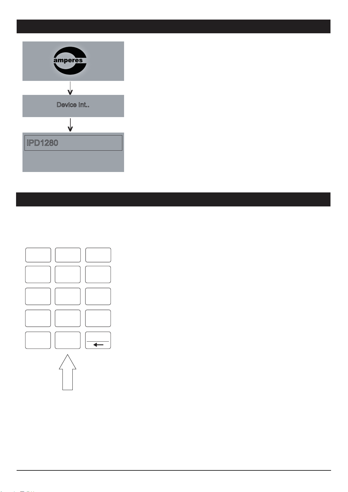
1. Default reset: Press & hold the reset button until LED “streaming” ON.
2. At the web browser, enter the IP address 192.168.0.100 and the page below shall appear. This is a “Safe Mode” page for
Browser or Firmware update.
Safe mode: Press & hold the reset button until LED “status” ON.
System firmware or Browser shall be updated once in a while when new features are available or to fix bugs. There are 2 meth-
ods of doing;
Server Reset Bootloading
If the client “hanged”, it is required to perform system reset by :
When it is required to update the units firmware for bugs fixing or features upgrade,
you can manage it by using browser at its designated IP address (default at
192.168.0.100).
Update via Browser
1.
2.
3.
To update, follow the steps below:
Download the updated firmware from our website or source it directly from our
service center. The file extension is “appbin”, save it in your PC.
Use browser (http) to access the unit, go to “ System Configuration ” and look for
“ Update Firmware ”. Click “ Select Firmware ” tab and locate the file saved earlier.
Finish the update, restart the device and the unit shall operate under latest firmware.

Unit Startup
PAGE 8 iPD1280 | ETHERNET PAGING MICROPHONE
Device Int..
iPD1280
Upon powering, the LCD display shall show the ‘Amperes logo’ and
thereafter ‘Device Initialising’.
Mic is ready for paging.
To operate the paging mic, please refer to section ‘Operating The Unit’
- page 14.
Setup Menu
1
4
2
5
3
6
7
CLR
8
0
9
ADD
F1 F2 F3
1) Press “0” button momentarily ( 3 seconds )
to enter Setup mode
2) Press “Add” button for next
3) Press CLR for Exit setup mode
When using for the first time, a simple setup is required such as:
1) Setting priority level
2) Optional setting for chime output, grouping, time out etc.
V01.00
The setup required can be performed via browser or alternatively directly to the unit. We recommend using web browser for
setup as this is the fastest and easiest way to do.

Setup Menu
PAGE 9iPD1280 | ETHERNET PAGING MICROPHONE
1. PRIORITY
2. CHIME
To enter the Setup Main Menu, press ‘0’
momentarily for 3 seconds and the first
setup menu - 1. PRIORITY shall appear.
3. GROUPING
4. KEY BEEP
5. TIME OUT
7. SYSTEM INFO
8. FACTORY RESET
Use ADD (Next ) button to scroll down the
menu, or CLR (Prev) to view previous
screen.
To enter a specific sub menu, press ‘0’
button.
If no entry is made within 15 seconds, the
setup menu shall exit automatically and
return to ready mode.
Setting priority level of the
paging mic.
Setting the chime type for mic
activation or off.
Enable or disable keypad sound
when pressed.
Setting time out period when
mic is activated.
Setting the paging server IP
address.
To reset and clear memories to
factory default.
ADD ( Next )
ADD ( Next )
ADD ( Next )
ADD ( Next )
ADD ( Next )
ADD ( Next )
ADD ( Next )
6. SYSTEM SETTINGS
ADD ( Next )
Firmware version information.
10. SAVE & EXIT?
NO
Setting the group for group a
zones.

Setup Menu
PAGE 10 iPD1280 | ETHERNET PAGING MICROPHONE
1. PRIORITY 1. PRIORITY
1.1 Set Priority: 1
1.1 Priority set : 2
Press “ 0 ” to enter this sub
menu from the main directory.
Return to PRIORITY menu
Press “0” for Enter
Press ‘ADD’
to select value
Press “0” for Save
This menu is to set the Priority
level of the paging mic. Priority
1 is highest while No Priority is
considered normal and is used
in single point paging setup.
Maximum can set 10 level
priority.
2. CHIME 2. CHIME
2.1 Start Chime :
2.1 Start Chime :
UP 1
Press “ 0 ” to enter this sub
menu from the main directory.
Press ‘CLR’, Return to
main menu
Press “0” for Enter
Press ‘ADD’ to select Tone or Off Tone
Press ‘0’ for Save
This menu is to set the chime
type when the paging mic is on
and followed by closing chime.
2.2 End Chime :
Press ‘ADD’ to select 2nd Chime
Press “0” for Enter
2.2 End Chime :
Down
Press “0” for Enter
Press ‘ADD’ to select Tone or Off Tone
Press ‘0’ for Save
Factory default setting is 1
Once priority level is deter-
mined, press ‘0’

Setup Menu
PAGE 11iPD1280 | ETHERNET PAGING MICROPHONE
3. GROUPING
3. GROUPING
3.1 Group 1
3.1.1 Zone (3)
Press ‘CLR’, Return to Main menu
Press “0” for Enter
Press “0” for Enter
Press “0” for Enter
3.1.1 Zone (3)
1,2,3
3.1.1 Zone (3)
Press “CLR” for Back
Press “ADD” for Next
Press “0” for Enter
3.1.2 Clear (3) YES
Press ‘ADD’ for
select Yes / No
Press “ 0 ” to enter this sub
menu from the main directory.
This menu is to create group of
zones and group names in the
system.
We recommend this setting to
be done to enable faster
response during paging.
Press “ADD” for the next group ( Group
1 till Group 8 )
To view zone setting
4. KEY BEEP 4. KEY BEEP
4. KEY BEEP
ON
Press “ 0 ” for Enter
Press “ ADD ” for Select On / Off
Press “ 0” for Save
Press ‘0’ to enter this sub menu from
the main directory.
To setup the “ Key Beep ” On/Off.

Setup Menu
PAGE 12 iPD1280 | ETHERNET PAGING MICROPHONE
T
5. TIME OUT 5. TIME OUT
5.1 Timeout
1min
Press “ 0 ” for Enter
Press “ ADD ” for Select
Press “0” for Save
Press ‘0’ to enter this sub menu from
the main directory.
This is to set the duration that the mic
to be in active mode.
Setting the timeout would prevent the
mic being turned on and left idle after
an announcement is made.
There are time when the mic is
required to be active for a longer
period of time, such as making a long
speech or performing a prayer using
the PA system
5.2 Display Timeout
1min
Press “ ADD ” for Select
Press “0” for Save
Press “ CLR ” for Back
6. SYSTEM SETTING 6. SYSTEM SETTING
6.1 Paging Server IP:
192.168.0.100
Press “ 0 ” for Enter
Press “0” for Enter
6.2 Data Port:
3000 Press “ 0 ” for Select
Press “ADD” to Next
6.3 IPAddress:
192.168.0.101
6.4 Subnet Mask:
255.255.255.0
Press ‘0’ to enter this sub menu from
the main directory.
To setup the IP address
Return to Main Page
Press “0” to Save
Press “ ADD ” for Next
6.5 Gateway Address:
192.168.0.1
Press “CLR” for Exit
Press “0” to Save
Press “ ADD ” for Next

Setup Menu
PAGE 13iPD1280 | ETHERNET PAGING MICROPHONE
7. SYSTEM INFO 7. SYSTEM INFO
7.1 Firmware Version
v0 1.00
7.2 Device Name
iPD1280
Press ‘0’ for Enter
Press “ADD” to Next
Press ‘0’ to enter this sub menu from the
main directory.
To check the firmware version of the
paging mic.
This is an important info when interfac-
ing with external equipment, to check
the compatibility as well as when servic-
ing is required.
8. FACTORY RESET 8. FACTORY RESET
8. FACTORY RESET
NO
Press ‘0’ for Enter
Press “ADD” to Select Yes / No
Press ‘0’ to enter this sub menu from the
main directory.
Selecting this menu would revert what-
ever setup done earlier to factory
default setting, such as zone groupings,
chime setting, etc.
9. SAVE AND EXIT 9. SAVE AND EXIT
9. SAVE AND EXIT
NO
Press ‘0’ for Enter
Press “ADD” to Select Yes / No
Press “0” for Enter

Operating The Unit
PAGE 14 iPD1280 | ETHERNET PAGING MICROPHONE
A successful paging can only be achieve if network is connected, without it would be incomplete installation. Initial setup such as
priority level should be set.
Follow the simple steps below to begin paging
1. DIRECT ZONE PAGING
Direct zone paging is when the user
select the required zone and press
CHIME + TALK button.
A chime shall be broadcasted followed
by illuminated ring at the gooseneck mic.
To end paging, simply press the CHIME
+ TALK button again which would be
followed by a downward chime.
Example :
Performing a paging to zone
1 and 15.
Press button “1”
Press button “ADD”
Press button “1” and “5”
Press “CHIME + TALK”
Talk when the LED ring at the mic is lit
and to end,
press “CHIME + TALK”
2. ALL CALL PAGING
To make an ALL CALL paging, simple
press the “ALL CALL” button, without
having to press “CHIME + TALK ” button.
Paging mic is ready for announcement
once the LED ring is lit.
To end paging, simply press the “ALL
CALL” button again.
In ALL CALL paging, all normal zones
shall be activated. This is however,
would not energise 24V DC overriding
supply to override volume controllers. To
enable overriding, we recommend the
usage of EP1200.
Example :
Making call to all normal
zones ( not overriding exter-
nal volume controllers ).
Press “ALL CALL”
Talk when the LED ring at the mic is lit
and to end,
press “ALL CALL”
Dialing
1,2,3,4,
Press G1 Button momentarily (2 seconds)
Zone grouping enable easy access to a group of zones for paging. Press button ‘1’ for group (1), press ‘ADD’ button to add
the group.
Saving
Group 1
Example of application :
All lobbies of different floors
can be lumped under single
group to allow simultaneous
paging to all the floors.
To Recall :
Press ‘G1’ and Press ‘Chime + Talk’
ZONE GROUPING

Technical Specifications
PAGE 15iPD1280 | ETHERNET PAGING MICROPHONE
24V DC
2.0W
1 x male barrel jack
Numerical keypad for Zones, Groups, Siren, All Call,
Repeat, Chime + Talk
Sensor touch keypad
Gooseneck condenser capsule; unidirectional
4 tone up and 4 tone down
Zone, power, audio, data, gooseneck ring LED
LCD display; white back illumination
100 - 12KHz @ 1KHz +/- 3 dB
>70 dB @ 1KHz
IMA ADPCM 36KHz 16 bit
Mic from local and Chime from Web
RJ45, 10 / 100T Base
TCP / IP, UDP, IGMP, HTTP
ADMP, ADP
Unicast & Multicast
( Web browser ) IE Ver 9 and above, Firefox or Google
Chrome ( preferred )
370 mm
230 x 192 x 65 mm ( Excluding Mic)
850 g
Operating voltage
Power consumption
24V power connector
Zone selection
Switching selection
Microphone
Chime
LED Indicator
Displays
Frequency response
S / N ratio
Audio conversion format
Audio output controls
LAN Interface
Protocols
Priority protocols
Transmission mode
User interface
Gooseneck mic length
Dimension (W x H x D)
Weight

Warranty Conditions
Disclaimer
AMPERES ELECTRONICS SDN BHD
MADE IN MALAYSIA
Published : APRIL 2019
ISO 9001: 2015
Design & Manufacture of Public Address Equipment and Systems
Certicate No. 16895 / A / 0001 / UK / En
Information contained in this manual is subject to change without prior notice and does not represent a commitment
on the part of the vendor. AMPERES ELECTRONICS SDN BHD shall not be liable for any loss or damages
whatsoever arising from the use of information or any error contained in this manual.
It is recommended that all services and repairs on this product be carried out by AMPERES ELECTRONICS SDN
BHD or its authorized service agents.
AMPERES series must only be used for the purpose they were intended by the manufacturer and in conjunction
with this operating manual.
AMPERES ELECTRONICS SDN BHD cannot accept any liability whatsoever for any loss or damages caused by
service, maintenance or repair by unauthorized personnel, or by use other than that intended by the manufacturer.
Only Amperes Electronics Service Centres are allowed to make warranty repairs : a list of Amperes Electronics
Service Centres may be asked for by the purchaser or send directly to Amperes Electronics Sdn Bhd at 70 Jalan
Industri PBP 3, Tmn Perindustrian Pusat Bandar Puchong, 47100, Puchong, Selangor, Malaysia or its authorized
dealers. This warranty is not valid if repairs are performed by unauthorized personnel or service centres.
This warranty covers only repairs and replacement of defective parts ; cost and risks of transportation as well as
removal and installation of the product from the main system are for the account of the purchaser. This warranty
shall not extend to the replacement of the unit.
This warranty does not cover damages caused by misuse, neglect, accident of the product as well as using the
product with power supply voltage other than shown on the product, or any other power supply source / adaptor
not recommended by the manufacturer.
This warranty does not cover damages caused by fire, earthquakes, floods, lightning and every cause not directly
related to the unit.
This warranty does not include any indemnity in favor of the purchaser or the dealer for the period out of use of the
unit; moreover the warranty does not cover any damages which may be caused to people and things when using
the product.
This warranty certificate is valid only for the described product, and is not valid if modifications are made on this
certificate or on the identification label applied on the product.
This warranty covers all the material and manufacturing defects and is valid for a period of 36 months from the
date of purchase or for a specified period in countries where this is stated by a national law. In this case, the
extension is valid only in the country where the product is purchased.
Amperes Electronics Sdn Bhd is not obliged to modify previously manufactured products under warranty if the
design changes or improvements are made.
Other manuals for iPD1280
1
Table of contents
Other Amperes Microphone manuals

Amperes
Amperes PD1280 User manual

Amperes
Amperes PM1060 User manual

Amperes
Amperes PM1060 User manual

Amperes
Amperes iEP1202 User manual

Amperes
Amperes iPD1280 User manual

Amperes
Amperes PD2400 User manual

Amperes
Amperes PD2800 User manual

Amperes
Amperes PM 1000 User manual

Amperes
Amperes PD1240 User manual

Amperes
Amperes PD1900 User manual