amperes
PD2800 Digital Paging Microphone PAGE 3
Parts Identification
T
1. Paging Microphone Inlet
XLR inlet for gooseneck microphone. Only condenser microphone supplied or those operates under 3 to 9 V.
2. LCD Display
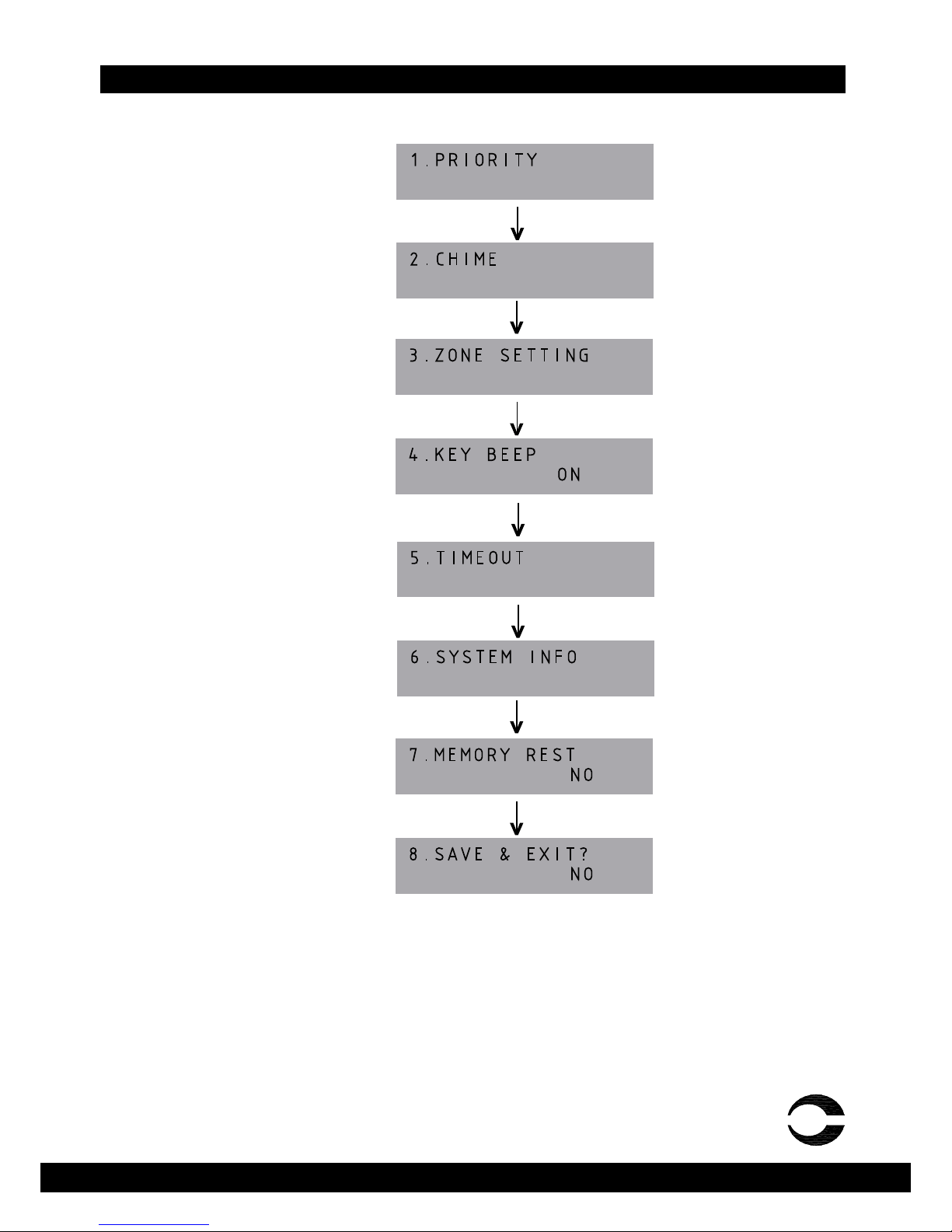
Factory default display is with back light. User has the option to turn off. Please refer to setup section.
3. ALL CALL Button
Mic shall be activated instantly without chime, triggering all normal zones. Note that makingALLCALLs will not trigger
the overriding relay at the zone selectors, thus the volume controllers set at minimum shall not be overrided.
4. Chime & Talk Button
Select the zones required before pressing this button.Achime shall start ( if selected ) and followed by mic activation,
which is indicated by the illuminated ring at the mic capsule.
5. Keypad
Zone selections and programming are done via these keypad.
6. Memory / Select Button
It is used for programming zone grouping during setup.
7. Group Recall / Enter Button
It is used to recall zone grouping during paging and also used as Enter key during setup.
8. Gooseneck Microphone
This detachable condenser mic comes with illuminated ring when the mic is in active mode and ready for paging.
9. Chime and Mic Volume Control
Individual volume for chime and microphone output level can be adjusted according to site requirement.
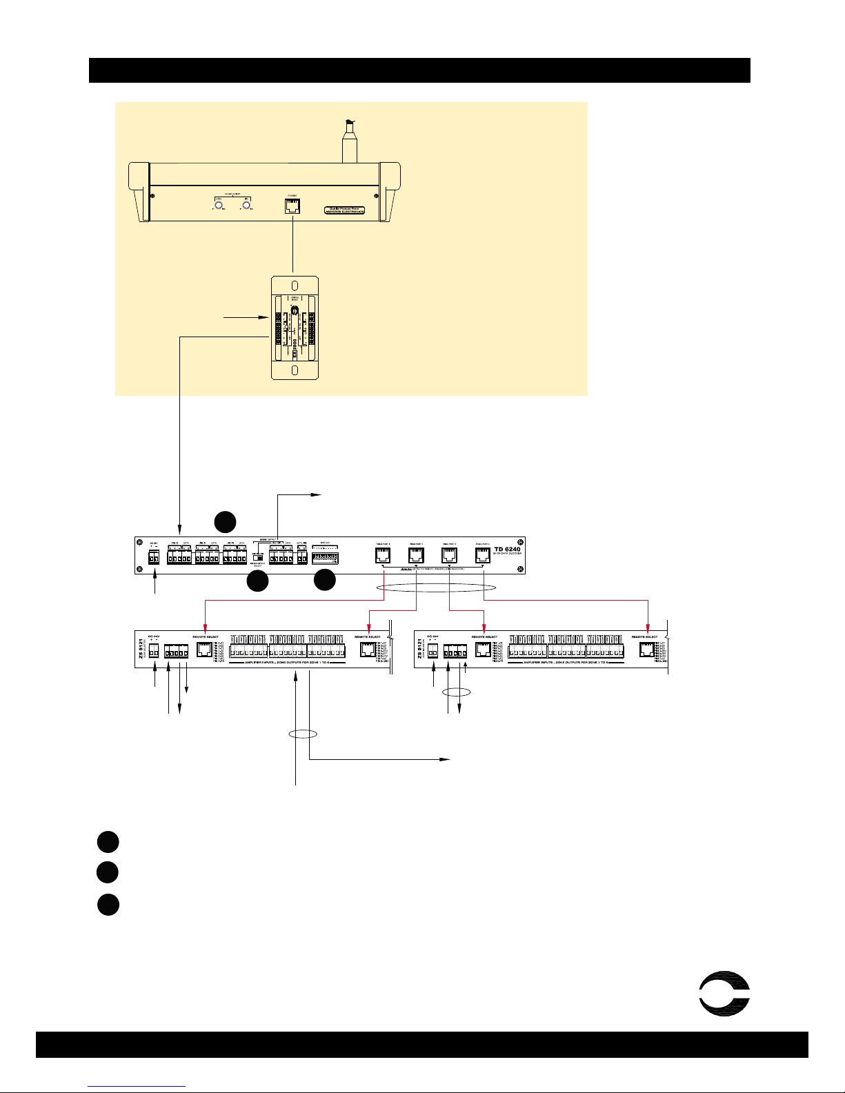
10. Output Connection
This RJ45 connection shall connect to EX2800 with the cable provided. Power supply to the unit is fed via EX2800.
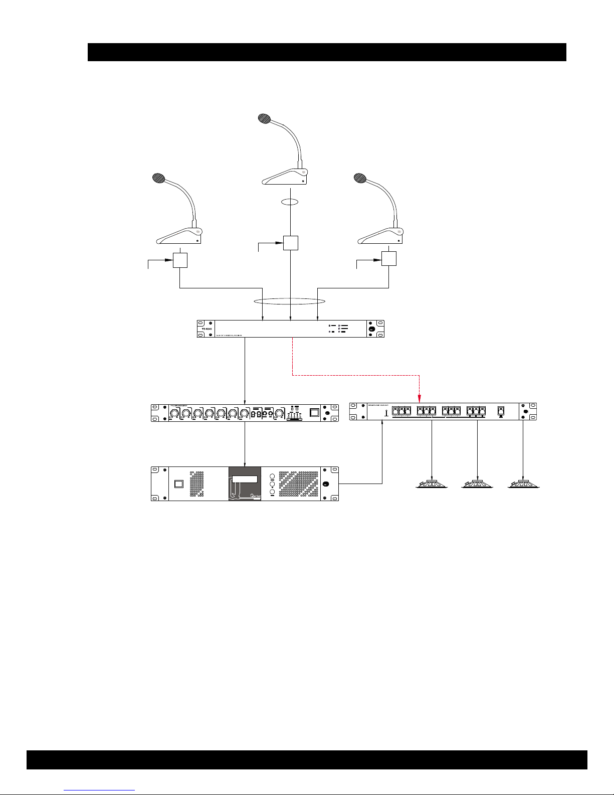
11. Data / Audio Output to Decoder
Data and audio are linked to TD6240 decoder unit using 2pair screen cable. Please refer to “Connecting the Unit” for
detailed connection diagram.
12. Data/Audio Input Link / DC Supply
Data and audio from other EX2800 ( if any ) are fed to this port forming a circuit. This connection is applicable only if
multipoint paging setup is established. Use a DC24V power adaptor supplied for powering the unit.
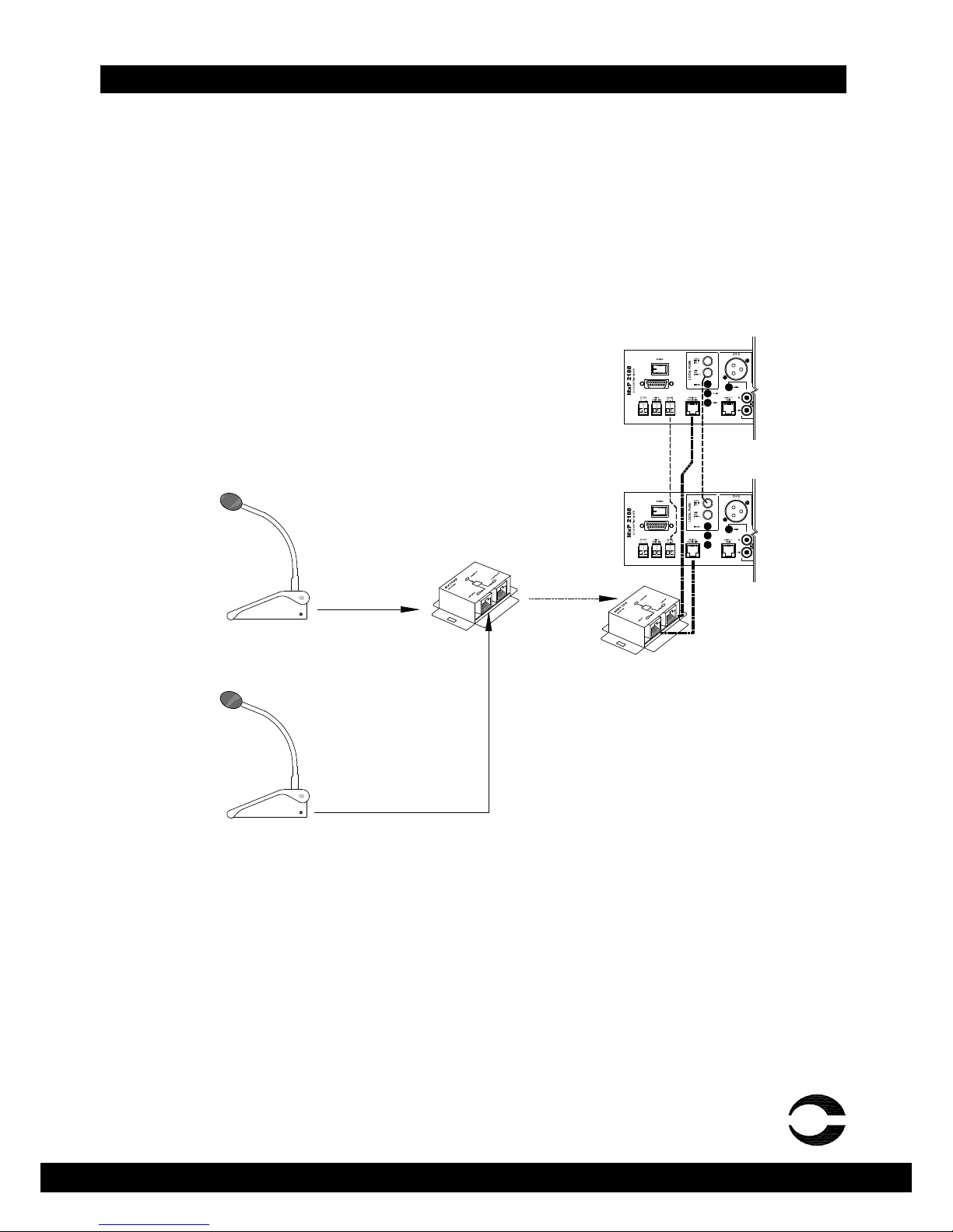
13. Paging Mic Connection
Connect to the paging mic via this RJ45 connector. For pin configuration, refer to the diagram.