RCF TX516 User manual

the rules of sound
TX
516
PX
516
User manual
User manual
User manual
Manuale d’uso
Manuale d’uso
Manuale d’uso
UHF WIRELESS MICROPHONES (- TRANSMITTERS)
RADIOMICROFONI (TRASMETTITORI) UHF

2
ITALIANO
INDICE ITALIANO
Avvertenze per la sicurezza pag. 2
TX 516 Descrizione pag. 4
TX 516 Personalizzazione pag. 5
PX 516 Descrizione pag. 6
Informazioni pag. 8
Inserimento e sostituzione delle batterie pag. 10
Dati tecnici pag. 12
ENGLISH INDEX
Safety precautions page 13
TX 516 Description page 15
TX 516 Personalization page 16
PX 516 Description page 16
Information page 19
How to insert and replace batteries page 21
Specifications page 23
Prima di collegare ed utilizzare questo prodotto, leggere attentamente le istruzioni contenute in
questo manuale, il quale è da conservare per riferimenti futuri.
Il presente manuale costituisce parte integrante del prodotto e deve accompagnare quest’ultimo
anche nei passaggi di proprietà, per permettere al nuovo proprietario di conoscere le modalità
d’installazione e d’utilizzo e le avvertenze per la sicurezza.
L’installazione e l’utilizzo errati del prodotto esimono la RCF S.p.A. da ogni responsabilità.
AVVERTENZE PER LA SICUREZZA
1. Tutte le avvertenze, in particolare quelle relative alla sicurezza, devono essere lette con
particolare attenzione, in quanto contengono importanti informazioni.
2. Non immergere questo prodotto nell’acqua (od in altri liquidi), non lanciarlo, non lasciarlo
cadere.
L’apparecchio non deve essere esposto alla pioggia o a spruzzi d’acqua che potrebbero
causare un corto circuito; evitare luoghi estremamente umidi.
3. Non eseguire sul prodotto interventi / modifiche / riparazioni se non quelle espressamente
descritte sul manuale istruzioni. Contattare centri di assistenza autorizzati o personale altamente
qualificato quando:
l’apparecchio non funziona (o funziona in modo anomalo);
acqua (od un’altra sostanza) è entrata nell’apparecchio;
l’apparecchio ha subito forti urti.
4. Nel caso che dal prodotto provengano odori anomali (o addirittura fumo), spegnerlo
immediatamente e rimuovere le batterie.
5. Non collegare a questo prodotto accessori non previsti.
•
•
•
IMPORTANTE

3
ITALIANO
6. Perdita dell’udito
L’esposizione ad elevati livelli sonori può provocare la perdita permanente dell’udito. Il livello di
pressione acustica pericolosa per l’udito varia sensibilmente da persona a persona e dipende
dalla durata dell’esposizione. Per evitare un’esposizione potenzialmente pericolosa ad elevati
livelli di pressione acustica, è necessario che chiunque sia sottoposto a tali livelli utilizzi delle
adeguate protezioni; quando si fa funzionare un trasduttore in grado di produrre elevati livelli
sonori, è necessario indossare dei tappi per orecchie o delle cuffie protettive.
7. Non puntare il microfono verso un diffusore vicino, onde evitare un possibile innesco
(effetto “Larsen”).
8. Per evitare fenomeni di rumorosità indotta, non usare questo prodotto in prossimità di
apparecchiature che producono campi elettromagnetici di forte intensità.
9. Collocare il microfono lontano da fiamme (o fonti di calore eccessivo).
10. Non forzare mai gli organi di comando (tasti e manopole).
11. Non usare solventi, alcool, benzina o altre sostanze volatili per la pulitura delle parti esterne.
12. Informazioni sulle batterie
Utilizzare possibilmente sempre batterie nuove per ottenere le prestazioni migliori.
Utilizzare batterie alcaline.
Non utilizzare contemporaneamente batterie vecchie e nuove.
Non utilizzare contemporaneamente tipi diversi di batterie.
Non utilizzare batterie ricaricabili.
Non tentare di ricaricare batterie non ricaricabili.
Verificare che sia rispettata la polarità delle batterie, seguendo le indicazioni riportate sul
relativo vano.
Togliere le batterie una volta esaurite o nel caso l’apparecchiatura non sia utilizzata per un
lungo periodo.
Non cortocircuitare le batterie (ad esempio collegando i 2 poli opposti con un filo di
metallo).
Smaltire le batterie esaurite negli appositi contenitori, facendo riferimento alle norme di legge
vigenti (nel paese di utilizzo) in materia di ecologia e protezione dell’ambiente.
•
•
•
•
•
•
•
•
•
•

4
ITALIANO
TX 516 - DESCRIZIONE
Il modello TX 516 è un radiomicrofono ad impugnatura con trasmettitore
che funziona nella banda UHF. È possibile selezionare la frequenza del
trasmettitore (tra le 16 disponibili) tramite un commutatore a 16 posizioni
posto all’interno.
1PULSANTE “ON/OFF” E “MUTE”
Premere il pulsante per un istante per
accendere il trasmettitore (il LED blu
2si illumina). Premendolo di nuovo, il
trasmettitore è posto nella condizione di
“mute” (il microfono è disattivato ed il LED
blu 2lampeggia lentamente); per ritornare
al funzionamento normale, premere ancora il
pulsante una sola volta.
Per spegnere il trasmettitore (LED blu 2
spento), è necessario tener premuto il
pulsante per almeno 4 secondi.
2INDICATORE LUMINOSO (LED BLU)
Il LED blu indica lo stato del trasmettitore e
delle batterie:
spento: trasmettitore spento
acceso (luce fissa): trasmettitore acceso e
funzionante
lampeggiante lento: trasmettitore acceso
ed in “mute”
lampeggiante veloce: batterie scariche
(che devono essere sostituite).
Nota: per accedere al controllo di sensibilità
ed al selettore di frequenza, premere
leggermente l’indicatore luminoso 2
all’interno dell’incavo e simultaneamente
sfilare il trasmettitore dal corpo facendo presa
sulla testa (vedere la sezione “inserimento e
sostituzione delle batterie”).
•
•
•
•
RCF S.p.A. Vi ringrazia per l’acquisto di questo prodotto, realizzato
in modo da garantirne l’affidabilità e prestazioni elevate.
mute
1
2
mute
S E NS
HL
3
0
8
1
1
2
2
3
3
4
4
4
4
4
5
5
5
5
5
6
6
6
6
6
7
7
7
7
7
F
E
D
C
B
A
7
4

5
ITALIANO
3CONTROLLO SENSIBILITA’ DELLA CAPSULA
Il controllo di sensibilità è situato all’interno del trasmettitore ed è
preimpostato in fabbrica ad un valore medio (adatto per la maggior parte
delle applicazioni).
Ad esempio, una sensibilità più alta (ruotando il controllo verso “H”) può
essere impostata per il solo parlato, mentre un’impostazione più bassa
(verso “L”) potrebbe essere necessaria per il canto.
Per ottenere una corretta impostazione della sensibilità, verificare che il
LED rosso PEAK (quando presente) sul ricevitore utilizzato lampeggi / si
accenda solo occasionalmente durante l’uso.
4SELETTORE DI FREQUENZA
Selettore della frequenza del trasmettitore (0: frequenza più
bassa; F: frequenza più alta).
ATTENZIONE: la selezione del canale deve avvenire a trasmettitore spento.
Assicurarsi che il trasmettitore ed il ricevitore siano sintonizzati sulla stessa
frequenza.
TX 516 – PERSONALIZZAZIONE
In dotazione vengono forniti cinque tappi colorati intercambiabili per la
personalizzazione del trasmettitore (necessaria nel caso di utilizzo simultaneo
di 2 radiomicrofoni).
Per la sostituzione: eseguire una pressione ai lati del tappo (figura A) e sfilarlo
completamente dal corpo in plastica (figura B), far coincidere la sagoma del
tappo desiderato con quella del corpo (figura C) e premere con forza fino
all’inserimento completo (figura D).
me
ut
t
mu e
mute
mue
t

6
ITALIANO
PX 516 – DESCRIZIONE
Il modello PX 516 è un trasmettitore per cintura, che funziona nella banda
UHF, da abbinare al microfono RCF (non incluso) LA 500 (“Lavalier”, da
cravatta) oppure HE 502 (“headset”, ad archetto). È possibile selezionare la
frequenza del trasmettitore (tra le 16 disponibili) tramite un commutatore a 16
posizioni posto sul retro.
1PULSANTE “ON/OFF” E “MUTE”
Premere il pulsante per un istante per
accendere il trasmettitore (il LED “pwr” 2si
illumina). Premendolo di nuovo, il trasmettitore
è posto nella condizione di “mute” (il microfono
è disattivato ed il LED “pwr” 2lampeggia
lentamente); per ritornare al funzionamento
normale, premere ancora il pulsante una sola
volta.
Per spegnere il trasmettitore (LED “pwr” 2
spento), è necessario tener premuto il pulsante
per almeno 4 secondi.
2INDICATORE LUMINOSO “pwr” (LED blu)
Il LED blu “pwr” indica lo stato del trasmettitore
e delle batterie:
spento: trasmettitore spento
acceso (luce fissa): trasmettitore acceso e
funzionante
lampeggiante lento: trasmettitore acceso e in
“mute”
lampeggiante veloce: batterie scariche (che
devono essere sostituite).
3INGRESSO AUDIO (linea / mic.)
Ingresso audio (con connettore jack 3,5
mm) per il collegamento di un microfono
RCF (non incluso) LA 500 (“Lavalier”, da
cravatta) o HE 502 (“headset”, ad archetto)
o di un segnale a livello linea.
4CONTROLLO SENSIBILITA’ “sns”
Controllo di sensibilità / guadagno (“line /
mic.”) dell’ingresso audio, da impostare a
seconda della sorgente audio utilizzata e del
mute
O N /
pe a k
line
sns
mic
pwr
123
4
5
58 ,6 5 0
58 ,9 7 5
86 3 ,0 50
8 63 ,4 2 5
- 86 3 ,8 00
D - 8 64 ,1 7 5
E - 8 6 4,5 5 0
F - 8 64 ,9 5 0
1
3
5
7
9
B
6

7
ITALIANO
livello del segnale: verso “mic” quando è collegato un microfono; verso “line”
quando si utilizza un segnale a livello linea. Per ottenere un’impostazione
ottimale, controllare che il LED rosso “peak” 5sul trasmettitore (ed anche sul
ricevitore, quando presente) lampeggi / si accenda solo occasionalmente
durante l’uso.
5INDICATORE LUMINOSO “peak” (LED rosso)
Il LED rosso “peak” si accende quando il segnale audio d’ingresso raggiunge
il livello massimo ammissibile. Durante l’uso, verificare che si accenda solo
occasionalmente.
6SELETTORE DI FREQUENZA
Selettore della frequenza del trasmettitore (0: frequenza più bassa; F:
frequenza più alta).
ATTENZIONE: La selezione del canale deve avvenire a trasmettitore spento.
Assicurarsi che il trasmettitore e il ricevitore siano sintonizzati sulla stessa
frequenza.
ALIMENTAZIONE “PHANTOM”
L’alimentazione “Phantom” (3,8 V c.c.) è sempre presente sul connettore jack
dell’ingresso audio.
Non cortocircuirtare mai l’alimentazione “Phantom” (con la massa) per non
causare danni al trasmettitore.

8
ITALIANO
INFORMAZIONI
FREQUENZE
BANDA “U-N” BANDA “U-UK”
CH. CH. CH. CH.
0 – 801,000 MHz 8 – 810,650 MHz 0 – 854,900 MHz 8 – 858,650 MHz
1 – 801,400 MHz 9 – 811,150 MHz 1 – 855,275 MHz 9 – 858,975 MHz
2 – 802,500 MHz A – 812,950 MHz 2 – 855,900 MHz A – 863,050 MHz
3 – 803,800 MHz B – 815,850 MHz 3 – 856,175 MHz B – 863,425 MHz
4 – 805,900 MHz C – 817,050 MHz 4 – 856,575 MHz C – 863,800 MHz
5 – 806,750 MHz D – 817,950 MHz 5 – 857,625 MHz D – 864,175 MHz
6 – 807,350 MHz E – 819,000 MHz 6 – 857,950 MHz E – 864,550 MHz
7 – 808,150 MHz F – 819,650 MHz 7 – 858,200 MHz F – 864,950 MHz
PROBLEMI D’INTERFERENZE
Il trasmettitore deve essere impostato sulla stessa frequenza del ricevitore
utilizzato: verificare la corrispondenza tra la frequenza del trasmettitore e
quella del ricevitore.
Nel caso di rumore di fondo oppure disturbi / interferenze, se possibile, è
consigliabile cambiare la frequenza (sia sul trasmettitore, sia sul ricevitore)
e/o ottimizzare la soglia di “squelch” del ricevitore (riferirsi al manuale d’uso
del ricevitore).
Suggerimenti per evitare eventuali problemi dovuti ad interferenze:
quando possibile, tenere il trasmettitore ad almeno 5 metri di distanza da
ogni ricevitore attivo;
le antenne dei ricevitori (quando sono esterne) non devono essere troppo
vicine tra loro;
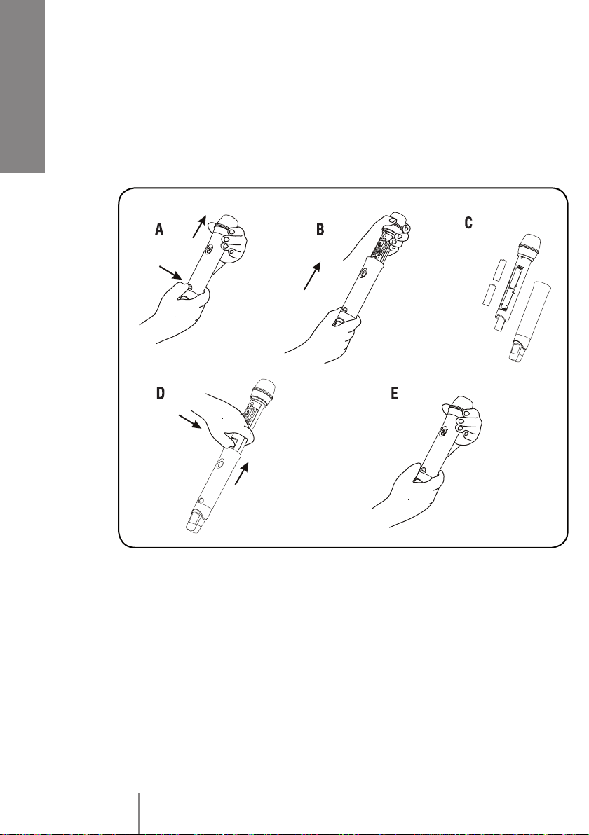
assicurarsi che le batterie del trasmettitore siano cariche ed efficienti;
controllare la soglia di “squelch” dei ricevitori (quando questo controllo
è disponibile), impostandola sul livello minimo che garantisce la portata
desiderata.
USO SIMULTANEO DI 2 TRASMETTITORI
È possibile l’utilizzo simultaneo di massimo 2 radiomicrofoni TX 516 / PX 516
(con frequenza diversa tra loro) per ciascuna banda (U-N oppure U-UK).
In caso di problemi durante l’utilizzo contemporaneo di 2 radiomicrofoni,
controllare le frequenze in uso; se possibile, utilizzare gli estremi della banda
(esempio: ch. 0 e ch. F).
Non è possibile l’utilizzo simultaneo di 2 trasmettitori aventi la stessa
frequenza.
•
•
•
•

9
ITALIANO
Nel caso d’interferenza, spegnere i 2 trasmettitori ed accertarsi che i relativi
ricevitori siano in condizione di “mute”; questo accorgimento consente di
identificare una possibile sorgente diretta di interferenza esterna.
Accendere un solo trasmettitore alla volta (muovendolo nell’ambiente per
verificare la condizione peggiore) ed identificare il ricevitore che esce dalla
condizione di “mute”.
Se un ricevitore non sintonizzato sulla frequenza del trasmettitore in uso esce
dal “mute”, si è in presenza di un problema di intermodulazione e pertanto
occorre allontanarlo o cercare una posizione più appropriata.
CAMPI ELETTROMAGNETICI
Per evitare che fenomeni induttivi diano luogo a ronzii e disturbi che
compromettono il buon funzionamento del sistema, non posizionare il
ricevitore in prossimità di apparecchiature che generano forti campi
magnetici (es. trasformatori di alimentazione, conduttori di energia elettrica,
linee diffusori, ecc.).
EFFETTO “LARSEN”
L’effetto Larsen (detto anche “feedback” acustico) è un suono fastidioso che
si genera quando i microfoni sono troppo vicini ed orientati verso i diffusori
acustici che emettono i suoni captati dai microfoni stessi. Per evitare l’effetto
“Larsen” (che può danneggiare gli altoparlanti), si raccomanda di mantenere
una certa distanza tra i microfoni ed i diffusori acustici, abbassare il volume
dei microfoni (se necessario) e non puntarli verso i diffusori acustici.
INTERRUZIONI DEL SEGNALE
È possibile che in certe zone sia difficile (per il ricevitore utilizzato) ricevere
correttamente il segnale. Nel caso vi siano delle interruzioni del segnale, si
consiglia di spostare il ricevitore in una posizione più appropriata, evitare di
interporre ostacoli e ridurre la distanza tra trasmettitore e ricevitore.
LICENZE D’USO
I trasmettitori RCF soddisfano pienamente tutte le normative in vigore.
Tuttavia, in alcuni paesi, il loro uso deve essere approvato dalle autorità locali
e potrebbe essere necessario richiedere una licenza (affinché l’utilizzo sia
legale).
Il vostro distributore locale sarà in grado di darvi tutte le informazioni
necessarie.

10
ITALIANO
INSERIMENTO E SOSTITUZIONE DELLE BATTERIE
AVVERTENZA: nel caso di prolungato inutilizzo del trasmettitore, si consiglia
di rimuovere le batterie per evitare possibili danni dovuti a perdite delle
batterie stesse.
TX 516
Premere leggermente l’indicatore luminoso all’interno dell’incavo e
simultaneamente sfilare il trasmettitore dal corpo facendo presa sulla testa
(figura A).
Sfilare completamente la parte interna dal corpo in plastica (figura B).
Inserire o sostituire le batterie nel vano predisposto prestando particolare
attenzione alle polarità +/– (figura C).
Inserire il trasmettitore di nuovo nel corpo, facendo coincidere
l’indicatore luminoso con la guida all’interno del corpo. Esercitare
una leggera pressione in corrispondenza dell’indicatore luminoso per
favorire l’inserimento (figura D).
Spingere sino in fondo il trasmettitore, prestando particolare attenzione
a posizionare correttamente sia il pulsante sia l’indicatore luminoso nelle
apposite sedi (figura E).
•
•
•
•
•
teum
NE SS H
L
mu et
-
+
+
t
u em
tm u e

11
ITALIANO
PX 516
Premere leggermente in corrispondenza del vano dello sportello (figura A)
e tirare.
Aprire completamente lo sportello (figura B) ed inserire o sostituire le
batterie nel vano predisposto, prestando particolare attenzione alle polarità
+/– (figura C).
Richiudere correttamente lo sportello (figura D).
•
•
•
OEC I
T H G SLE N O
B
d
UH POKETT NSMI
TR
FCRA TE
8
60P
ES
O
HG E
TL IN O
C
B
d
M
TTRI
OCATTE
UHN R
FK
PES
5P
80
S
TLIN
E OH EG
O
C
B
d
OSTH KTAI
FT
PT
EMR
U C RNE
0P
85
+
+-
-

12
ITALIANO
DATI TECNICI TX 516
Batterie
Risposta in frequenza
Distorsione
Assorbimento (corrente)
Banda
Potenza d’uscita RF
Modulazione
Deviazione
Compander
Antenna
Temperatura di funzionamento
Stabilità in frequenza (– 10 ÷ + 50 °C)
Limitatore d’ingresso
Avviso di batterie scariche
Durata batterie
(dipende dall’uso e dalla loro carica)
Peso
3 V (2 x 1,5 V) modello AA Alcalina
35 Hz ÷ 16 kHz (3dB)
< 1%
60 mA (a 3V)
UHF, 799 ÷ 865 MHz (16 canali)
< 30 mW ERP
F3E (modulazione di frequenza)
35 kHz nom. a 1 kHz sinusoidale
Quadratico
Integrata
– 10 ÷ + 50 °C
ETSI EN 300 422-1/-2
ETSI EN 301 489-1/-9
EN 61000-3-2/3
Sì
Sì
> 20 ore (dato indicativo)
0,23 kg (con batterie)
DATI TECNICI PX 516
Batterie
Sensibilità ingresso audio
Risposta in frequenza
Distorsione
Assorbimento (corrente)
Banda
Potenza d’uscita RF
Modulazione
Deviazione
Compander
Antenna
Temperatura di funzionamento
Stabilità in frequenza (– 10 ÷ + 50 °C)
Limitatore d’ingresso
Indicazione “peak” (picco)
Avviso di batterie scariche
Durata batterie
(dipende dall’uso e dalla loro carica)
Peso
3 V (2 x 1,5 V) modello AA Alcalina
Regolabile: 50 mV ÷ 5 V RMS
35 Hz ÷ 16 kHz (3dB)
< 1% (a deviazione nominale)
60 mA (a 3V)
UHF, 799 ÷ 865 MHz (16 canali)
< 30 mW ERP
F3E (modulazione di frequenza)
35 kHz nom. a 1 kHz sinusoidale
Quadratico
Integrata
– 10 ÷ + 50 °C
ETSI EN 300 422-1/-2
ETSI EN 301 489-1/-9
EN 61000-3-2/3
Sì
Sì
Sì
> 20 ore (dato indicativo)
0,12 kg (con batterie)

13
ENGLISH
ENGLISH INDEX
Safety precautions page 13
TX 516 Description page 15
TX 516 Personalization page 16
PX 516 Description page 16
Information page 19
How to insert and replace batteries page 21
Specifications page 23
Before connecting and using this product, please read this instruction manual carefully and keep
it on hand for future reference. This manual is to be considered an integral part of this product and
must accompany it when it changes ownership as a reference for correct installation and use as well
as for the safety precautions.
RCF S.p.A. will not assume any responsibility for the incorrect installation and / or use of this
product.
SAFETY PRECAUTIONS
1. All the precautions, in particular the safety ones, must be read with special attention, as they
provide important information.
2. Do not put the microphone into water (or another liquid), do not throw it, do not let it falling down.
This device shall not be exposed to rain.
Make sure that no objects or liquids can get into this product, in order to avoid any possible
short circuit.
3. Never attempt to carry out any operations, modifications or repairs that are not expressly
described in this manual.
Contact your authorized service centre or qualified personnel should any of the following
occur:
The product does not function (or functions in an anomalous way).
Objects or liquids have got into the unit.
The product has been subject to a heavy impact.
4. If this product begins emitting any strange odour (or even smoke), switch it off immediately and
remove the batteries.
5. Do not connect this product to any equipment or accessories not foreseen.
•
•
•
•
IMPORTANT
NOTES

14
ENGLISH
6. Hearing loss
Exposure to high sound levels can cause permanent hearing loss. The acoustic pressure level
that leads to hearing loss is different from person to person and depends on the duration of
exposure. To prevent potentially dangerous exposure to high levels of acoustic pressure, anyone
who is exposed to these levels should use adequate protection devices. When a transducer
capable of producing high sound levels is being used, it is therefore necessary to wear ear plugs
or protective earphones.
7. Do not aim the microphone to near loudspeakers, in order to avoid feedback.
8. To prevent inductive effects from causing hum and noise, do not use this product in the vicinity
of equipments that produce high-intensity electromagnetic fields.
9. Keep the microphone far from any excessive heat source.
10. Never force the control elements (keys, knobs, etc. ).
11. Do not use solvents, alcohol, benzene or other volatile substances for cleaning the external
parts.
12. Information about batteries
Use (when possible) always new batteries to get the best performance.
Use alkaline batteries.
Do NOT use old and new batteries at the same time.
Do NOT put together different models of batteries.
Do NOT use rechargeable batteries.
Do NOT attempt to charge non rechargeable batteries.
Verify the batteries’ polarity is correct (inserted properly, following the indication on the
relevant compartment).
Remove batteries when empty or in the case the device will not be used for a long time.
Do NOT short-circuit batteries (i.e. by connecting the 2 poles together with a metallic wire).
Throw empty batteries into dedicated garbage can, according to the present laws (of your
country) about ecology and environment protection.
•
•
•
•
•
•
•
•
•
•

15
ENGLISH
TX 516 – DESCRIPTION
TX 516 is a hand-held wireless microphone and an UHF transmitter, which
its carrier frequency can be chosen (among the 16 available) through an
internal 16 position selector.
1‘ON/OFF’ and ‘MUTE PUSH-BUTTON’
Push (and immediately release) the button
to switch the transmitter on (the blue LED
2turns ON). Push it again to mute the
microphone (the blue LED 2blinks slowly);
push it once more for normal operating.
Push and hold (at least 4 seconds) to
switch the transmitter off (the blue LED
turns OFF).
2BLU LED
The blue LED indicates the transmitter state
and the battery charge:
OFF: the transmitter is switched off
ON: the transmitter is switched on and
operating
Slow blinking: the transmitter is switched
on, but its mic is muted.
Fast blinking: empty batteries (that need
replacing).
Note: the sensitivity control and the
frequency selector are easily accessible:
press lightly the blue LED 2and
simultaneously pull the transmitter out of its
body by holding its head (read the ‘How to
insert and replace batteries’ section).
3MIC. CAPSULE SENSITIVITY CONTROL
The sensitivity control is inside the
transmitter body and factory preset to a
medium level (usually suitable for many
purposes).
RCF S.p.A. thanks you for purchasing this product, which has been
designed to guarantee reliability and high performance.
mute
1
2
mute
S E NS
HL
3
0
8
1
1
2
2
3
3
4
4
4
4
4
5
5
5
5
5
6
6
6
6
6
7
7
7
7
7
F
E
D
C
B
A
7
4

16
ENGLISH
For instance, a higher sensitivity (by turning the control to H) could be set for
vocal speech only, a lower setting (to L) could be necessary for a singer.
To adjust the sensitivity correctly: verify that the ‘peak’ red LED (if present) of
the used receiver only flashes occasionally when using the transmitter.
4FREQUENCY SELECTOR
Transmitter carrier frequency / channel selector (0: the lowest frequency;
F: the highest frequency).
IMPORTANT: the channel is to be selected when the transmitter is OFF!
Make sure that both the transmitter and the receiver are tuned to the same
frequency.
TX 516 – PERSONALIZATION
Every transmitter is equipped with five interchangeable coloured caps to
personalize it when 2 wireless microphones are simultaneously used.
Cap substitution: press the cap sides (A) and pull the cap out of the plastic
body (B), the outline of the desired cap and the one of the plastic body must
coincide (C), then press the cap until it is completely inserted (D).
PX 516 – DESCRIPTION
PX 516 is a belt pack transmitter that operates in the UHF band. It should be
matched to either a RCF LA 500 ‘Lavalier’ or HE 502 ‘headset’ microphone
(not included).
It is possible to select the carrier frequency through a 16 position switch
placed at the transmitter back.
me
ut
t
mu e
mute
mue
t

17
ENGLISH
1‘ON/OFF’ and ‘MUTE’ button
Push and immediately release the button to
switch the transmitter on (the ‘pwr’ LED 2
turns on).
At the second push, the transmitter turns to
the ‘mute’ mode (the microphone is off and the
‘pwr’ LED slowly blinks); push the button again
to reset the normal operation. Push and hold
the button (at least 4 seconds) to switch the
transmitter off (the ‘pwr’ LED 2turns off).
2‘pwr’ (power) blue LED
The ‘pwr’ blue LED indicates the transmitter
state and the battery charge:
OFF: the transmitter is off
ON: the transmitter is on and operating
Slowly blinking: the transmitter is on, but in
‘mute’ mode
Fast blinking: empty batteries (that need
replacing).
3AUDIO INPUT (line / mic)
Audio input (via 3.5 mm jack connector) to
connect an RCF microphone (not included)
LA 500 (‘Lavalier’) / HE 502 (‘headset’) or a
line level signal.
4‘sns’ SENSITIVITY CONTROL
It adjusts the audio input sensitivity / gain (line
/ mic) that should be set according to the used
audio source and its signal level: to ‘mic’ when
a microphone is connected, to ‘line’ for a line
level signal.
During its use, an optimal adjustment is
achieved when the red ‘peak’ LED 5on the
transmitter (and also on the receiver, when
present) only flashes occasionally.
5‘peak’ red LED
The ‘peak’ red LED turns on when the input audio signal reaches the
maximum level.
Verify it only flashes occasionally (when using).
mute
O N /
pe a k
line
sns
mic
pwr
123
4
5
58 ,6 5 0
58 ,9 7 5
86 3 ,0 50
8 63 ,4 2 5
- 86 3 ,8 00
D - 8 64 ,1 7 5
E - 8 6 4,5 5 0
F - 8 64 ,9 5 0
1
3
5
7
9
B
6

18
ENGLISH
6FREQUENCY SELECTOR
It switches the transmitter carrier frequency (0: lowest; F: highest).
IMPORTANT: the channel selection must be done when the transmitter is OFF.
Make sure the transmitter and the receiver are tuned to the same frequency.
PHANTOM POWER SUPPLY
Phantom power (3.8 V dc) is always present on the audio input (jack
connector).
Never short circuit the phantom power (to the ground), as this may damage
the transmitter.

19
ENGLISH
INFORMATION
FREQUENCIES
‘U-N’ BAND ‘U-UK’ BAND
CH. CH. CH. CH.
0 – 801.000 MHz 8 – 810.650 MHz 0 – 854.900 MHz 8 – 858.650 MHz
1 – 801.400 MHz 9 – 811.150 MHz 1 – 855.275 MHz 9 – 858.975 MHz
2 – 802.500 MHz A – 812.950 MHz 2 – 855.900 MHz A – 863.050 MHz
3 – 803.800 MHz B – 815.850 MHz 3 – 856.175 MHz B – 863.425 MHz
4 – 805.900 MHz C – 817.050 MHz 4 – 856.575 MHz C – 863.800 MHz
5 – 806.750 MHz D – 817.950 MHz 5 – 857.625 MHz D – 864.175 MHz
6 – 807.350 MHz E – 819.000 MHz 6 – 857.950 MHz E – 864.550 MHz
7 – 808.150 MHz F – 819.650 MHz 7 – 858.200 MHz F – 864.950 MHz
INTERFERENCE PROBLEMS
A transmitter is to be tuned to the same frequency of the dedicated receiver;
always check / compare the 2 frequencies.
In case of hum / noise due to interferences, if possible, it is advisable to change
frequency (on both transmitter and receiver) and optimize the receiver ‘squelch’
threshold (refer to the relevant user manual).
Advice to avoid any interference problem:
When possible, keep the transmitter at a distance of at least 5 meters from
each active receiver.
The receivers antennas (when external) should not be too close to each
other.
Make sure that transmitter batteries are charged and efficient.
Check the receiver ‘squelch’ threshold (when this control is available); set it
to the to the minimum level that allows to use the transmitter in the desired
range.
SIMULTANEOUS USE OF 2 TRANSMITTERS
It possible to use at the same time max. 2 TX 516 / PX 516 transmitters (tuned to
different carrier frequencies) per each band (U-N or U-UK).
In case of problems when using 2 transmitters simultaneously, check the selected
frequencies.
If possible, use the band limit channels (i.e.: ch. 0 and ch. F).
It is NOT possible to use at the same time 2 transmitters tuned to the same
carrier frequency.
•
•
•
•

20
ENGLISH
In case of interference, turn the 2 transmitters off and make sure that the
relevant receivers are in the ‘mute’ condition.
This procedure allows you to identify a possible direct external interference
source.
Turn on only 1 transmitter at a time, move it around to check the worst condition
and identify which is the receiver exiting from the ‘mute’ condition.
If a receiver not tuned to the frequency of the used transmitter exits from
the ‘mute’ condition, there is an inter-modulation problem and, therefore, it is
necessary to increase the distance between the transmitter and that receiver
(or find a better position).
ELECTROMAGNETIC FIELDS
To avoid the system is disturbed by hum / noise due to any inductive
phenomena, do not put the receiver near any equipment producing a
significant electromagnetic field (e.g. power transformers, electrical cable,
loudspeaker lines, etc.).
‘LARSEN’ EFFECT (AUDIO FEEDBACK)
The ‘Larsen’ effect (also known as audio feedback) is an unwanted sound
loop that occurs when live microphones are too close to (and pointed at)
loudspeakers emitting the same sounds captured by microphones. To avoid
the ‘Larsen’ effect (that may damage loudspeakers), keep a minimum distance
between microphones and loudspeakers, if necessary turn the microphone
volume down. Never point microphones at loudspeakers.
SIGNAL DROPOUTS
In certain areas it might be difficult (for the receiver) to receive the signal
correctly. Should signal dropouts occur, it may be necessary to move the
receiver to a most suitable position, to remove any obstacle and reduce the
distance between transmitter and receiver.
USE LICENCES
RCF transmitters fully meet all regulations in force.
Yet, in some countries, the use of radio systems must be approved by
local authorities and it may be necessary to get a licence (for legal use).
Your local distributor will provide you all necessary information.
This manual suits for next models
1
Table of contents
Languages:
Other RCF Microphone manuals