AMS AS3460 User manual

Document Feedback
AS3460
Content Guide
Demo Kit Manual •PUBLIC
UG000480 •v3-00 • 2021-Nov-08
126 │2
Content Guide
1Introduction ................................... 3
1.1 Evaluation Kit ...............................................3
1.2 Ordering Information ....................................4
2Quick Start Guide.......................... 5
2.1 Hardware Setup ...........................................5
2.2 Project Setup................................................6
2.3 Measurements & Calibration........................6
2.4 Simulation Window.......................................8
2.5 Filter Tuning..................................................9
2.6 Tooltips.......................................................11
3Evaluation Board..........................12
3.1 Default Jumper Setting...............................12
3.2 Power Supply .............................................13
3.3 Power ON/OFF...........................................19
3.4 Headphone Connectors .............................19
3.5 Line Input Connectors ................................21
3.6 Digital Microphone Connectors..................22
3.7 Raspberry Pi Board....................................25
3.8 I2C Communication.....................................25
3.9 I2S Selection...............................................26
3.10 GPIO Buttons .............................................27
3.11 Measurement Header.................................28
3.12 AS3460 IC..................................................30
4PCB Design...................................32
4.1 PCB Layout Recommendation...................33
5FleX Filter Description .................40
5.1 Filter Tabs...................................................40
5.2 Importing Biquad Coefficients ....................50
6ANC Tuning Guide .......................56
6.1 Feedback....................................................56
6.2 Feed Forward.............................................61
6.3 Example......................................................62
7ALC Tuning Guide........................66
7.1 Introduction.................................................66
7.2 Overview.....................................................66
7.3 Measuring ALC Headphones.....................67
7.4 Project Setup..............................................70
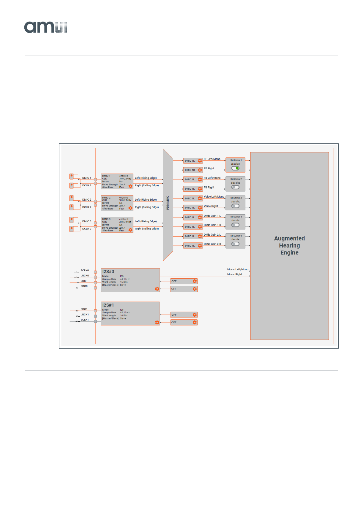
7.5 Signal Routing and System Configuration..76
7.6 Feed Forward Tuning –Low Leak Static....76
7.7 Feed Forward Tuning –High Leakage and
Adaption......................................................79
7.8 Feedback Filter...........................................82
7.9 Music Compensation..................................84
7.10 Algorithm Parameters.................................87
7.11 ELF Stage...................................................90
8Dual Chip Operation....................91
8.1 How to Operate in Dual Mode?..................91
9I2S Swap Function.......................95
10 Automatic Preset Selection
(APS).............................................97
10.1 How Does Automatic Preset Selection (APS)
Work? .........................................................97
10.2 Using APS in Flex.....................................101
10.3 Simple APS Example ...............................103
11 ANC Characterization................111
12 ALC Characterization ................113
12.1 Characterization Methods.........................113
13 Codec Mode ...............................118
14 Deep Sleep Mode.......................120
15 Wind Noise Detection................121
15.1 Overview...................................................121
15.2 Operation..................................................122
15.3 General Tuning Process...........................123
15.4 Parameters...............................................124
16 Revision Information.................125
17 Legal Information.......................126

Document Feedback
AS3460
Introduction
Demo Kit Manual •PUBLIC
UG000480 •v3-00 • 2021-Nov-08
126 │3
1 Introduction
The AS3460 is a digital augmented hearing companion device ideally suited for stereo headsets and
headphones as well as True Wireless applications. The extremely small form factor enables unique
augmented hearing experience for its end user with negligible influence on overall playtime of the
headset due to ultra-low power consumption. The high integration factor of AS3460 combined with its
all new Augmented Hearing Engine do allow for lowest power signal processing especially tailored for
the needs of active noise cancelling- and augmented hearing applications. The powerful low latency
digital signal processor (AHE) supports up to 250 Bi-Quad calculations to ideally match the
requirements of todays sophisticated acoustics designs and small form factors. Unique digital signal
processor (DSP) functions like seamless ANC crossfading or its integrated music feedback
compensation engine do allow lifting up user’s augmented hearing experience to its next level.
The development phase of such applications could be challenging and with this document, there are
some guideline listed to support customers in the product design. Below is a detailed description of the
AS3460 Evaluation Board and the configuration software FleX. Also some instructions are given
regarding ANC filter design.
The first section contains a quick start guide for the Evaluation Kit.
1.1 Evaluation Kit
The AS3460 Evaluation Kit package includes the following:
●AS3460 Evaluation Board
Figure 1:
Evaluation Board Hardware

Document Feedback
AS3460
Introduction
Demo Kit Manual •PUBLIC
UG000480 •v3-00 • 2021-Nov-08
126 │4
●FleX Filter Design Tool
This tool allows customers to design filters for the AS3460 ANC device.
Figure 2:
FleX Filter Design Tool Software
1.2 Ordering Information
Ordering Code
Description
AS3460_EVALUATION_BOARD
AS3460 Digital Augmented Hearing Demo Kit

Document Feedback
AS3460
Quick Start Guide
Demo Kit Manual •PUBLIC
UG000480 •v3-00 • 2021-Nov-08
126 │5
2 Quick Start Guide
This section will explain some key features of FleX required for starting an ANC-Filter project.
To install the latest FleX software please visit: ams.com and login with your email address and your
password. If you do not have a login yet, please request one by clicking on “Create Account“ in the
“Login” section.
When successfully logged in, you can download the latest evaluation software in the products section
under tools.
Please make sure that you have connected the AS3460 Evaluation Board to your PC before you
install Flex Software the first time. This is mandatory for proper device driver installation.
2.1 Hardware Setup
To use FleX, it is necessary to connect the AS3460 Evaluation Board’s RaspberryPi via USB to a
windows computer. When connecting the RaspberryPi for the first time, it will show up as a mass
storage device, which contains the drivers that are required for FleX to function properly.
When creating a new project or opening an existing one, FleX will connect to the evaluation board.
The default IP-address and port for this is 169.254.0.2:8080.
Figure 3:
Essential Connectors on the Evaluation Board
USB
Power Switch
3x PDM Input
L/R Headphone Differential Output

Document Feedback
AS3460
Quick Start Guide
Demo Kit Manual •PUBLIC
UG000480 •v3-00 • 2021-Nov-08
126 │6
2.2 Project Setup
The first step when starting with a blank FleX Project is to make the necessary hardware configuration
in the routing tab. Depending on the headphone’s wiring, the correct PDM microphone must be routed
to the corresponding filter. Here “DMIC 1L” refers to the first PDM interface, selecting on the rising
clock edge, “DMIC1R” is the microphone synced on the falling edge.
Figure 4:
Minimal Routing Configuration
2.3 Measurements & Calibration
Next is loading the XLS files obtained from the characterization (for more details see appendix A on
characterization) The AudioPrecision template provided by ams produces all the necessary files, with
the same naming scheme used by FleX.
Characterization data for several samples can be loaded, to check how the filter performs on the
various samples of the same headphone, thereby avoiding overfitting.

Document Feedback
AS3460
Quick Start Guide
Demo Kit Manual •PUBLIC
UG000480 •v3-00 • 2021-Nov-08
126 │7
Load data by navigating to the project tab and select the required files by clicking on the dots symbol
on each line.
Figure 5:
Measurement Sets
Depending on the measurement setup it will be necessary to calibrate the measurements. To do so
click on the eye symbol next to the affected measurement.
Example, if the measurement device’s output is balanced, but the headphone amplifier is connected
single-ended, the signal will lose 6dB, which then should be compensated for:

Document Feedback
AS3460
Quick Start Guide
Demo Kit Manual •PUBLIC
UG000480 •v3-00 • 2021-Nov-08
126 │8
Figure 6:
Gain and Phase Offset
If the headphone’s speaker is wired inverse to the AS3460 than it was wired at the time of
characterization it is necessary to compensate this using the “Phase offset”. It is not necessary to
calibrate for the test speaker or reference microphone, since their impact cancels out in the
calculations.
2.4 Simulation Window
The simulation window consists of three plots; the first two comprise a Bode-plot. In the Bode-plot the
ANC-filters and their target (or ideal Filter) can be viewed alongside each other. It is possible to drag
out the tuning tab and view it parallel to the filter tuning tab. This way it is possible to tune filters and
see the effect immediately. In the bottom plot FleX shows a prediction of the ANC-performance and
the total noise reduction.

Document Feedback
AS3460
Quick Start Guide
Demo Kit Manual •PUBLIC
UG000480 •v3-00 • 2021-Nov-08
126 │9
There are some basic controls for navigating the simulation window:
Figure 7:
Simulation Window Controls
Command
Action
Shift + Mouse wheel
Zoom with respect to frequency
Ctrl + Mouse wheel
Zoom with respect to Y-axis
Double Click inside plot
Reset view
Click + Hold
Drag plot
2.5 Filter Tuning
For tuning both a feed forward and a feedback system, FleX offers intuitive tuning of predefined filters.
For successful filter design it is crucial to be aware of how each filter type impacts both phase and
magnitude. The appendix contains a tutorial on how to tune the filters for feedback and feed
forward ANC.
There are three main types of filters available:
Figure 8:
Low/High Pass
●Adjustable
frequency
●Roll off of
-6 dB/Oct.
●-45° phase shift
at the roll off
frequency

Document Feedback
AS3460
Quick Start Guide
Demo Kit Manual •PUBLIC
UG000480 •v3-00 • 2021-Nov-08
126 │10
Figure 9:
Peak/Notch
Figure 10:
Shelf
Furthermore there is an Allpass filter and a 1st order x2 and you can also import biquad coefficients
into Flex so you can load all types of filters with that.
●Adjustable
frequency
●Gain
●And Q
●Adjustable
frequency
●Separate gains
for frequencies
higher and
lower than the
center
frequency
●Gain transition
with 6dB/Oct.

Document Feedback
AS3460
Quick Start Guide
Demo Kit Manual •PUBLIC
UG000480 •v3-00 • 2021-Nov-08
126 │11
A fixed number of instances of these filters can be used to build a filter. They can be controlled from
the tuning tab.
After completing a filter tuning, the filter can be activated on the AS3460 by clicking “Write to AHE”.
2.6 Tooltips
Within the Flex Software there is an extensive documentation of the features via Tooltips. Just hover
over a function or button you want to know more about and the Tooltips are displayed immediately.
If the Tooltips functionality is not needed, you can also deactivate it via “Help –Disable Tooltips”.
Figure 11:
Tooltips Example

Document Feedback
AS3460
Evaluation Board
Demo Kit Manual •PUBLIC
UG000480 •v3-00 • 2021-Nov-08
126 │12
3 Evaluation Board
All block functions on the AS3460 Evaluation Board are explained in detail below.
3.1 Default Jumper Setting
The Evaluation Board has default jumper settings, which are marked in the color “Orange” below.
Figure 12:
Default Jumper Configuration
Figure 13:
Table - Default Jumper Configuration
Designation
Function
Conditions
J24
Select Supply
5 V USB to Power
J15
AS3460/Raspi
CSDA0 to CSDA0 Raspi
J16
AS3460/Raspi
CSCL0 to CSCL0 Raspi
J22/21
I2S Selection
AS3460 Open = ADC
J28
3.3 V –3.3 V ADC
ADC Supply

Document Feedback
AS3460
Evaluation Board
Demo Kit Manual •PUBLIC
UG000480 •v3-00 • 2021-Nov-08
126 │13
3.2 Power Supply
There are three different options to supply the hardware.
Figure 14:
Different Supply Options
The schematic drawing describes the different supply options, which can be chosen by setting the
jumper J28 accordingly.
Figure 15:
Schematic - Different Supply Options

Document Feedback
AS3460
Evaluation Board
Demo Kit Manual •PUBLIC
UG000480 •v3-00 • 2021-Nov-08
126 │14
●Option 1: 5 V USB
Plug 5 V USB cable from the PC to the “Power 5 V- USB Connector” on the Raspberry Pi Board.
Ensure that the USB port of the PC is USB 3.0. This setting will be the standard configuration setting
on the board.
Figure 16:
Select Supply –Power Pin –5 V USB
Therefore, set on the “Select Supply” header the “Power Pin – 5V USB”.
Please see jumper setting in Figure 17 below.
Figure 17:
Select Supply –Power Pin to “5 V USB”

Document Feedback
AS3460
Evaluation Board
Demo Kit Manual •PUBLIC
UG000480 •v3-00 • 2021-Nov-08
126 │15
●Option 2: External Supply (headers and connectors)
The Evaluation Board can be powered via an external power supply (3.3 V –5 V) or with a Li-Ion-
Battery, which can be connected to the “External Supply” headers or connectors.
Figure 18:
External Supply (headers and connectors)
The schematic below shows the external power supply connectors.
Figure 19:
Schematic - External Supply (headers and connectors)
Therefore, set on the “Select Supply” header the “Power Pin – ext. Supply Pin”.
Please see jumper setting in Figure 20 below.

Document Feedback
AS3460
Evaluation Board
Demo Kit Manual •PUBLIC
UG000480 •v3-00 • 2021-Nov-08
126 │16
Figure 20:
Select Supply –Power Pin to “ext. Supply”
●Option 3: Li-Ion Battery
The Evaluation Board can be powered via a Li-Ion-Battery, which can be soldered on the bottom side
of the PCB. There are two solder pins, called “LI-ION-Battery Connection –Bat+1 / Bat-1” available.
Then the customer has a board, which works in standalone mode.
Figure 21:
LI-ION Battery Connection
Figure 22:
LI-ION Battery - Schematic

Document Feedback
AS3460
Evaluation Board
Demo Kit Manual •PUBLIC
UG000480 •v3-00 • 2021-Nov-08
126 │17
Therefore, set on the “Select Supply” header the “Power Pin – LI-ION Bat. Pin”.
Please see jumper setting in Figure 23 below.
Figure 23:
Select Supply –Power Pin to “LI-ION Bat”
At the PMU (Power Management Unit) section, there is a charger assembled, which provides the
proper supply for the battery.
Figure 24:
Charger –Schematic
In addition there are DCDCs (3V3, 1V8) assembled, which provide the power supply for the AS3460
IC.

Document Feedback
AS3460
Evaluation Board
Demo Kit Manual •PUBLIC
UG000480 •v3-00 • 2021-Nov-08
126 │18
Figure 25:
Measurement Pins –Power Pin and DCDCs
There are also measurement pins of the DCDC (below the Raspberry Pi PCB)
Power Pin 3.3 V DCDC to 3.3V and Power Pin 1.8 V DCDC to 1.8 V.
Figure 26:
DCDC Schematic

Document Feedback
AS3460
Evaluation Board
Demo Kit Manual •PUBLIC
UG000480 •v3-00 • 2021-Nov-08
126 │19
3.3 Power ON/OFF
The device start-up and power-down is controlled with the EN pin of AS3460. A rising edge on the EN
input pin will trigger start-up of the device. Once EN pin is high the integrated regulators are powering
up to generate analog audio- and digital core supply voltage. The EN pin of AS3460 is typically
controlled with a GPIO of the host device.
Power down of AS3460 is triggered by pulling EN pin low for minimum time. Once this minimum time
is reached, the power down sequence is initiated and no more I2C commands from the host device are
accepted. The chip fades out ANC and audio playback to avoid pop noise when shutting down the
device completely.
Connect the power supply to the board (choose one of the three options mentioned above).
To enable the AS3460 on the evaluation board, the “Enable AS3460” switch has to be
powered/switched on. If the AS3460 is powered, the LED above the switch is on.
Figure 27:
Power ON/OFF Switch
3.4 Headphone Connectors
The AS3460 features two fully differential stereo headphone amplifier outputs, which are suitable for
direct connection to external speakers. Each channel is designed to support speaker loads of typically
32 Ω down to 16 Ω.
With a supply voltage (AVDD) of 1.5 V the amplifier is capable of delivering an output power of typ.
26 mW into a 32 Ω load. In case a 16 Ω speaker is connected the maximum possible output power
can be increased to 52 mW per channel.
Headphone connectors (3.5 mm audio jack connectors and headers) for the left and the right headset
side are available.

Document Feedback
AS3460
Evaluation Board
Demo Kit Manual •PUBLIC
UG000480 •v3-00 • 2021-Nov-08
126 │20
In general, the LEMO connectors are not assembled on the evaluation board, but the footprints are
available on the board. These LEMO connectors are used for all ams reference designs (reference
earbud demonstrators).
Figure 28:
Headphone Connectors
The LEMO connectors can be soldered on the evaluation board. For soldering, it is mandatory to
follow the pinout according to the evaluation board schematic below.
Figure 29:
LEMO Connector Pinout
Connectors can be found on the LEMO homepage: www.lemo.com/pdf/EPG.1B.310.HLN.pdf
Other manuals for AS3460
1
Table of contents
Other AMS Motherboard manuals

AMS
AMS CCS811 User manual

AMS
AMS AS5 47D-TO EK ST Series User manual

AMS
AMS TMF882X-SHIELD User manual

AMS
AMS AS621 Series User manual

AMS
AMS AS3930 User manual

AMS
AMS JetCis 130 User manual

AMS
AMS AS5 Series User manual

AMS
AMS AN5000 Series Installation and operating instructions

AMS
AMS TMF882X User manual

AMS
AMS OSRAM NanEye User manual